meshmapperCalibration tool for dome projection using a spherical mirror and single projector.Available for Mac OS-XWritten by Paul Bourke July 2007
Subsequent notes for a 8m dome (Updated 2012)
Compatibility Issue: It seems that XQuartx is no longer working (or supported) on Tahoe, this spells the end of "meshmapper" as it currently stands. Working on an alternative ...
"meshmapper" is a utility that allows one to create precise warping maps for projection systems using a single projector and a spherical mirror, a technique called variously "sphemir" and "mirrordome". These may be upright domes such as these, planetariums such as these, and even more exotic spherical environments such as these. The following is a brief outline of the procedure one might use, please note that because the software described here is "utility" style UNIX application, one is expected to have some technical skills ... it is also still evolving. In essence the software is a simulator that takes as inputs the geometric and optical characteristics of the projection system. Some of these parameters can be measured reasonably accurately, others are more difficult. The idea is that one inputs an image for which the result on the projection surface is known, the parameters are then adjusted until the correct (known) visual result is obtained on the projection surface. For example, in a dome one knows the correct appearance of a polar grid (lines of longitude and latitude) such as the following image: radialgrid.tga.zip. 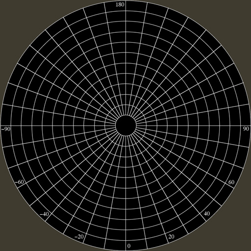
If the correct parameters are applied to the simulator then the image will appear correct on the dome, "meshmapper" allows the operator to interactively modify the parameters until the correct visual effect is obtained, for example, for an upright dome this would be the test pattern appearing on the dome as follows. 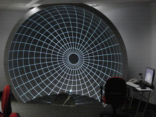
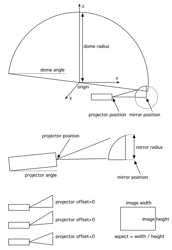
The parameters required fall into three groups as follows:
While some parameters such as the positions of the components can be measured reasonably accurately, others can be determined less well. In particular, estimating the projector throw (varies with zoom setting), the projector tilting and offset angle. These can be varied using keyboard controls in order to achieve a precise match. For example, the image and settings (top left corner panel) for the above calibration is shown below. 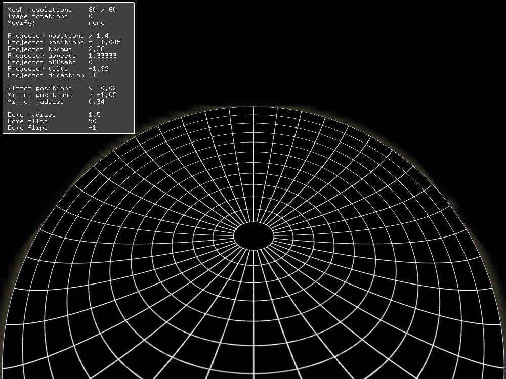
The parameters are changed by first selecting which object will be modified (projector, mirror, or dome) by using the keys "p", "m", or "d". The object being modified is indicated in the panel on the top left of the display. Parameter values are then changed by using the lower and upper case of various letters, lower case decreases the value, upper-case increases the value. So for example once the mirror object is chosen, then hitting the "r" key will reduce the radius of the mirror, while "R" will increase the radius of the mirror. Positions of the mirror and projector (dome is fixed at the origin) can only be adjusted in the x-z plane using the keys "x", "X", "z", and "Z". For more details see the usage string below, "meshmapper" is a command line utility, the following string is displayed with "meshmapper -h".
Usage: meshmapper [options] tgaimage
Options
   -h     this text
   -p     use a polar mesh rather than cartesian
   -f     full screen
   -d     verbose/debug mode
   -r s   read existing geometry file
Left mouse button for popup menus

Keyboard
          h     camera home
          p     choose to modify projector
          m     choose to modify mirror
          d     choose to modify dome
  0,1,2,3,4     choose to modify mesh node
          n     modify nothing
        x,X     modify position (projector, mirror, mesh)
        z,Z     modify position (projector, mirror, mesh)
        y,Y     modify position (mesh)
        r,R     modify radius (mirror or dome)
        a,A     modify tilt angle (projector or dome)
        b,B     modify bearing (dome)
        t,T     modify throw (projector)
        o,O     modify offset (projector)
          f     modify dome top (dome)
          w     windowdump
      esc,q     quit
Various additional options are available through the pop-up menus (right mouse button). Of particular note is the mesh resolution and the image geometry. The keyboard keys shown in the usage above are also available on screen, see the "Toggle interface help" in the pop-up menu. The current settings are saved in a file called "last.cfg" that will be saved in the same location as the application. A few starting point configuration files (.cfg) are provided These can be used as starting points for the two different orientations (rename them "last.cfg"). These are just text files and can be edited as such before running "meshmapper", indeed this is usually the way one would start with a new calibration. At the time of writing the aspect ratio (typically 16x10 or 16x9) can only be set by editing this file. Once the calibration is complete a warping mesh file can be written using the "Save XYUV warp mesh", see the pop-up menus. The file saved is called "test_xyuv.data", this is the file that is used to warp fisheye frames (in this example) and is described here and used for example in this warp-on-the-fly movie player. Coordinate conventions
Installation instructions
It is assumed that the user is familiar with the Apple operating system and has at least some familiarity with running UNIX style applications from the command line.
Notes
Update: June 2017
Due to unaccounted errors in some components, a node based distortion has been added. Examples of these errors might be non-spherical or local distortions in the spherical mirror, and even non-spherical domes (eg: inflatables). These node position are shown below, one simply types one of the digits from 0 to 4 and the the "x", "X", "y" or "Y" keys will shift or scale those positions on the warp mesh. 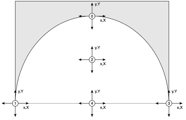
Display preferences: 2022
In the past, the warping tools by the author expected the external display (projector) and laptop or iMac display to be mirrored. The new Tools for Spherical Mirror Projection all expect the displays not to be mirrored. But currently meshmapper still requires mirroring. In addition, the last 2 versions of the MacOS have made some changes to how mirroring is handled, fortunately these are changes for the better. The key when mirroring for meshmapper is to optimise for the external display (projector). This ensures that meshmapper ends up using the correct aspect ratio typically 1.777777 or 1.6 in the config file. 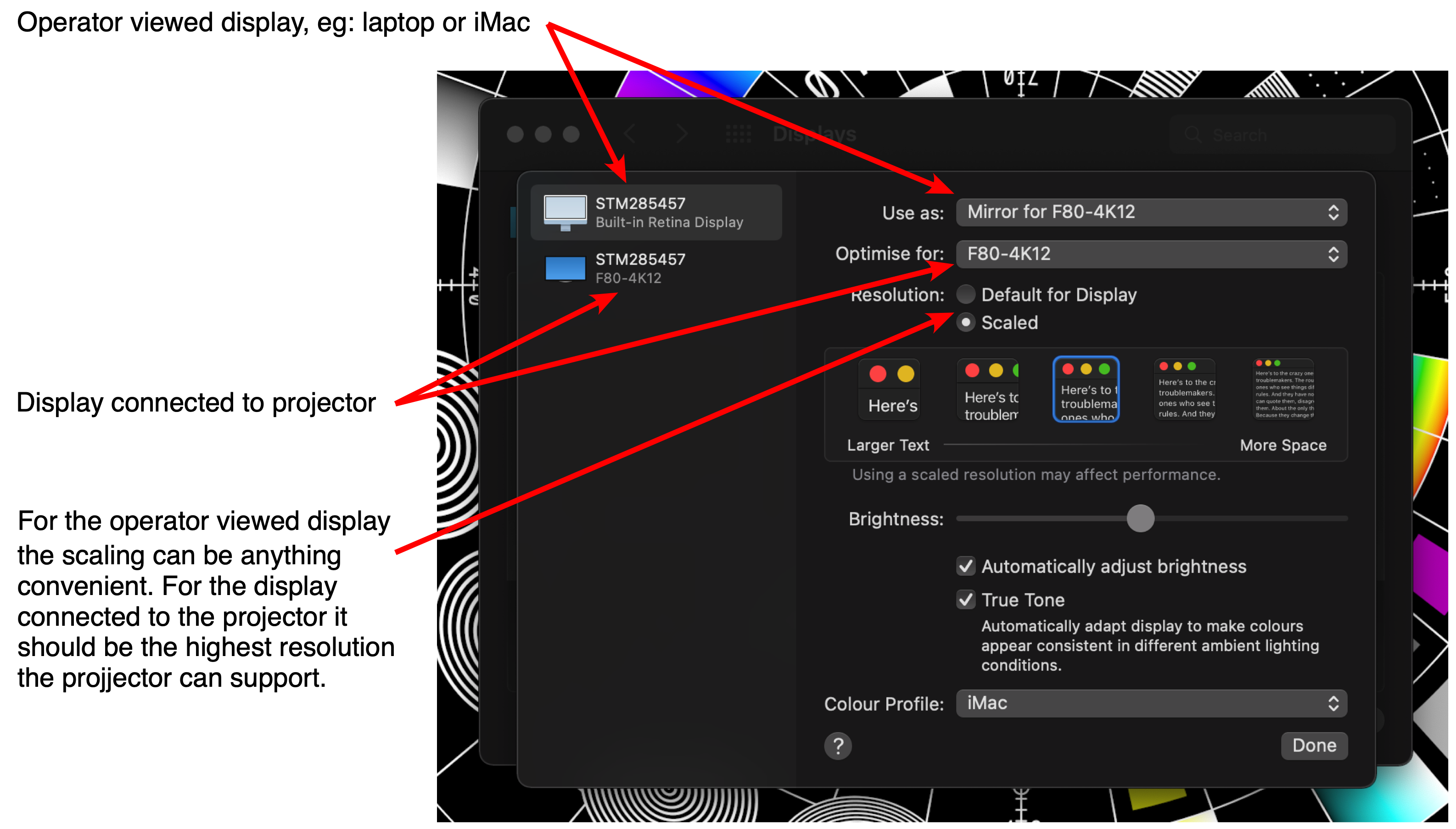
Monterey version, August 2022
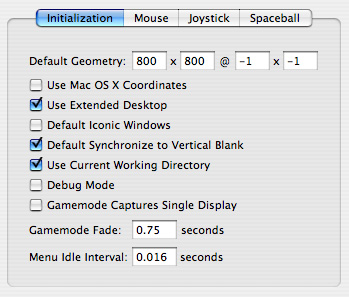
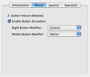
For reasons not fully understood by the author, some key aspects of X11 have changed (or been broken) in Monterey. There is now a special build for Monterey but it requires that the preferences in XQuartz need to be set as follows. This would seem necessary in order to get a totally full screen window, something required for meshmapper. 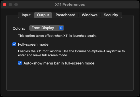
Please note that once meshmapper is quit (using "q" or ESC) one still needs to quit from the fullscreen XQuartz, either with command-q or command-, to reveal the preferences pane, or moving the mouse to menu bar and choosing the quit menu item in the XQuartz menu. Question
How do I go about writing my own warping software? Answer:
It turns out the mathematics is quite intractable ... by that I mean hard to solve because of the variables required to define a data projector. So all my alignment work has involved a simulation of the physical parameters. So, you need the geometry and optics of projector, the spherical mirror and the dome. You can see the parameters that go into my simulation in the top left of the second image above. What one does is imagine a ray through a grid sampling of the projectors rectangular frustum. This ray, in 3D space hits the spherical mirror (or not), is reflected through standard equal angle of incidence and reflection about a normal of the intersection point on the sphere, it then hits the dome (or not). Given the point on the dome you can work out what the 3D fisheye ray coordinate (phi,theta) and in turn the position (r,theta) on the 2D fisheye image. At this point you have a mapping between the fisheye (u,v) coordinate and the position in the image being projected. So if you create a mesh where the vertices are the original grid sampling, the texture coordinate is the calculated (u,v) coordinate. Complicated, but once you get the hang of it the concept is easy, the rest is in the details. |