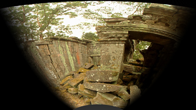
iSpherePaul BourkeJanuary 2007
Concept drawing for an immersive display consisting of a 360 degree display surface horizontally and 120 degree vertically. Top View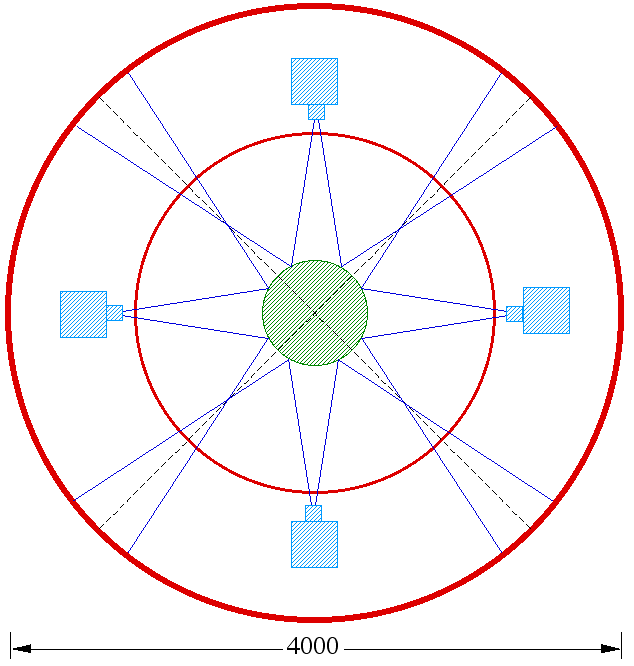
Side View 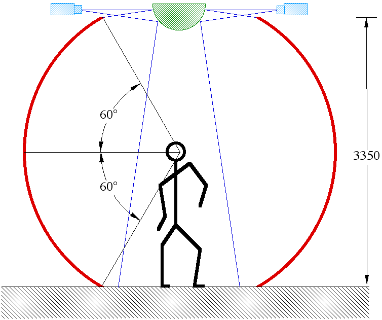
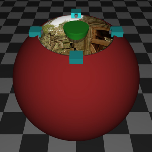
3D view A 3D view with the same component colour coding is shown below, all the components are to scale. 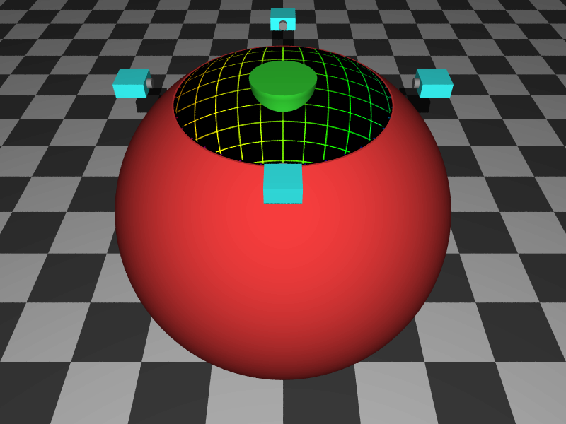
Image map The natural image projection is a spherical projection, the following test pattern is used in the above (interior surface) and will be used to illustrate warping and edge blending in what follows. Note this is a spherical projection of a polar map showing lines of latitude and longitude. 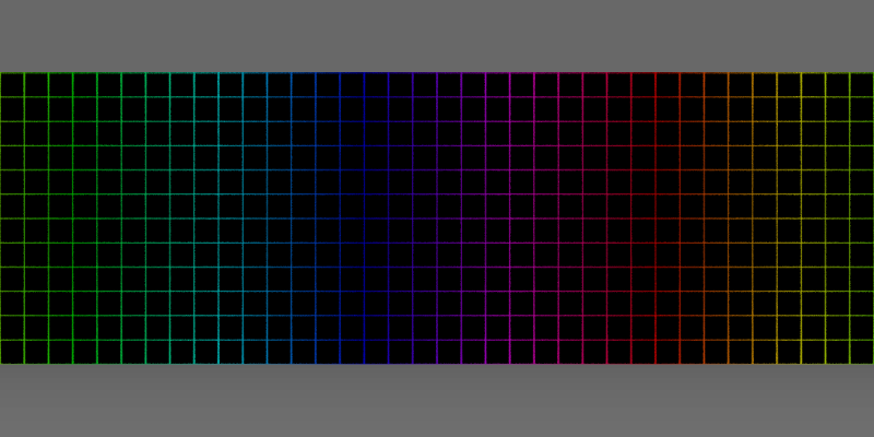
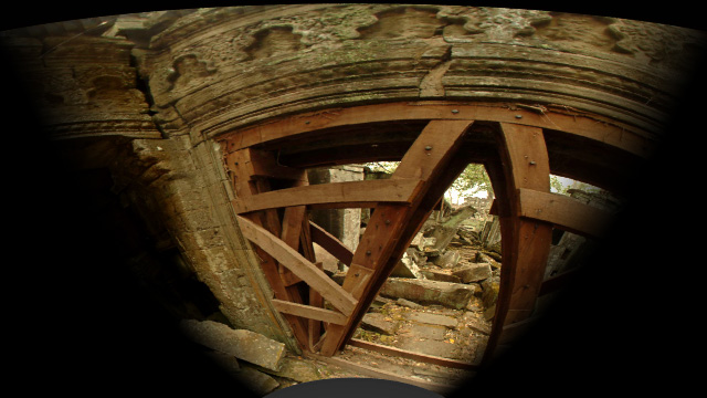
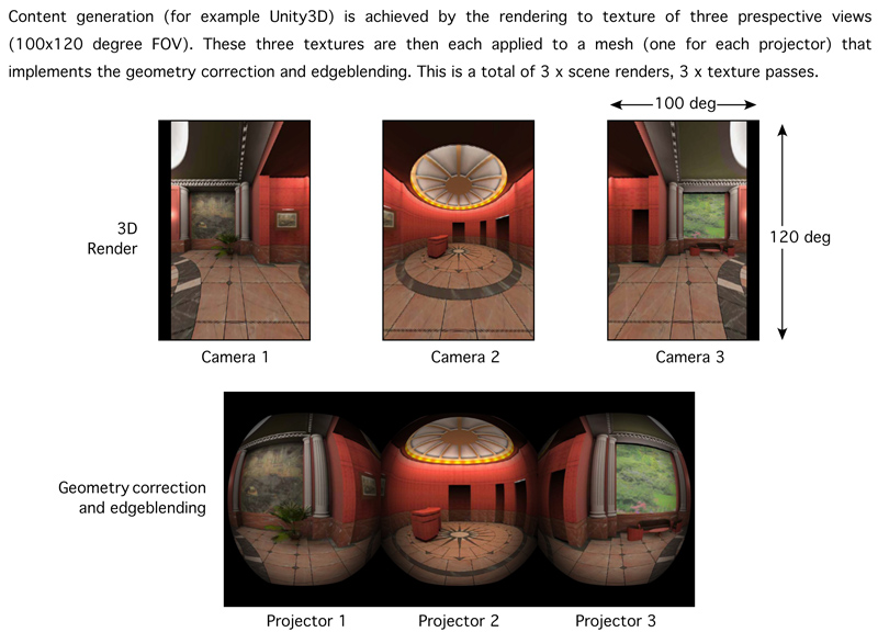
Image warping In order to see the type of image distortion required one can place a virtual camera in the position of each projector and with identical frustums (taking account of throw distance, aspect, offset, etc). The following is one of the cameras, the white lines frame each 90 section of the sphere (and the equator) and outline the region that each projector is required to cover. While the projected image can extend all the way to the top and bottom of the frame, some extra image is required on the left and right hand sides for edge-blending. 
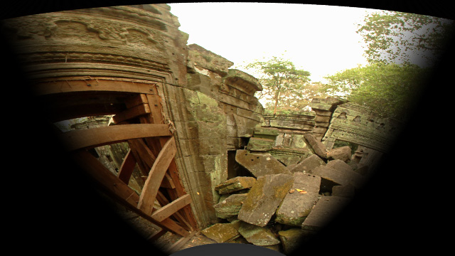
Edge blending Each 90 degree section needs to be edge-blended with the sections illuminated by the neighbouring projectors. The edge blend mask is as follows, it is derived by calculating the warped version of a spherical projection with vertical edge-blend zones at +-45 degree intervals. The image projected is multiplied by this mask, the exact transition across the edge-blend zone needs to take into account the gamma for each r,g,b channel. 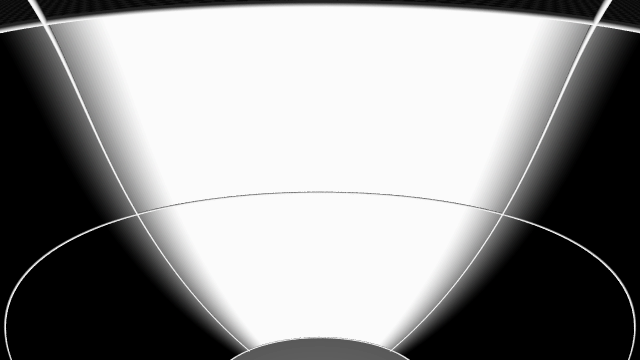
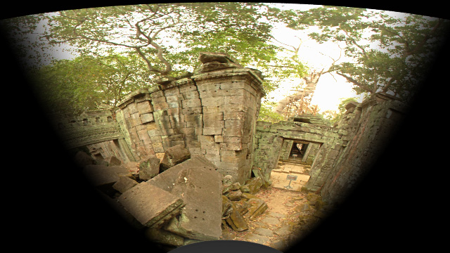
Projected image The final projected image with edge blending that will give rise to the test pattern of figure 2 is as follows. Note that a 16:9 aspect (HD) projector has been used, that aspect ratio is a better fit to spherical warping than 4:3. 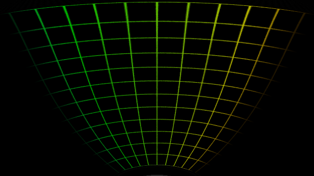 Notes
Mouse HMDOctober 2011
A three projector solution is proposed as a trade-off between the final resolution on the dome and the overall system complexity. Following based upon the InFocus IN5108, an SXGA+ (1400x1050) projector that supports vertical lens shift (symmetric frustums simplify geometry correction and edge-blending). Throw is 1.8:1, aspect ratio 3x4 (projectors mounted sideways). Lower cost XGA (1024x768) projectors could be substituted for a lower resolution effect.! Estimated average of 10 pixels per degree. Three projectors can be achieved with a single head graphics card and a Matrox triple-head-2-go unit. 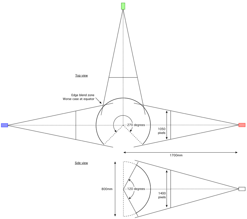
Improved coverage at the north pole can be achieved by raising the projectors above the midline and compensating by either using the horizontal lens shift and/or rotating the projectors downwards. This is at the expense of less coverage at the south pole. 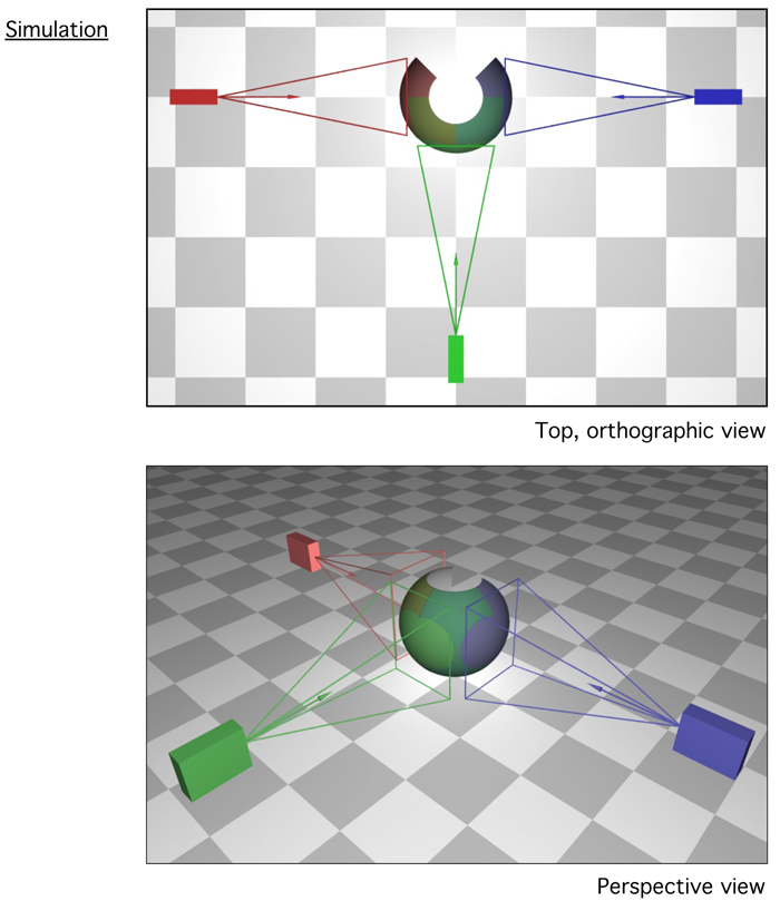
|