Capturing high resolution stereoscopic panorama imagesWritten by Paul BourkeIn collaboration with Jeffrey Shaw and Sarah Kenderdine June 2018 Abstract
Immersive experiences that leverage the capabilities of the human visual system typically seek to support the following capabilities: depth perception through stereopsis, engagement of peripheral vision, high visual acuity. Achieving this within real-time synthetic environments, such as a game engine, involves a means of presenting two rendered views to each eye, tracking the viewer within the space and supplying a sufficiently wide field of view at a high resolution. Presenting real-world photographically derived imagery meeting these requirements is considerably more problematic. For example, a photograph or video only captures a scene from a particular position whereas a computer generated rendering of a scene can be generated at will from any position. A so called omnidirectional stereoscopic panorama (ODSP) is a well established technique of capturing a 360 degree field of view stereoscopically. Strictly speaking the ODSP is only an approximation to the correct stereo pairs that should be presented to the viewer, but it an approximation that has been born out to be acceptable when the correct views cannot be created synthetically. A number of cameras have been proposed and constructed to capture an ODSP, in the following we will present the latest development, an approach due largely to the evolving capabilities of consumer level cameras. Introduction
Omnidirectional stereoscopic panoramas (ODSP) is the term given to a pair of locally correct stereoscopic panoramas spanning 360 degrees in longitude. "Locally correct" because if a limited horizontal field of view of the ODSP is presented to a viewer, there are minimal perceived stereoscopic artefacts irrespective of the part of the panorama being viewed. This is in contrast to more traditional stereoscopic image pairs that require knowledge of the viewers position to be strictly correct. In practical terms this means that an ODSP can be presented in, say, a 360 degree cylinder containing multiple observers all potentially looking in different directions. Similarly an ODSP can be experienced within a virtual reality (VR) headset with no other view dependent computation than selecting the correct portion of the panorama image pair as the viewer turns their head. In contrast, for most VR environments the exact view presented to each eye needs to be computed for all viewer positions and view directions. While this can be achieved for real time rendering, it is not possible for photographically captured imagery or computer based rendering or visualisation that cannot be computed in real time. The theory behind the ODSP was variably introduced in the 1990s by Ishiguro et al and various camera and software designs published by Peleg including an option employing a single camera. Employing an ODSP provides for the presentation of stereoscopic photographic imagery while minimising departures from the exact image pairs that should be presented to each eye. There are two sources of error, the first arises when the viewer is not located in the same position in relation to the viewing apparatus as where the ODSP was captured. For example if the viewer is not located in the center of a cylindrical display environment, or in the context of a VR headset the viewer is not located in the center of the virtual cylinder on which the ODSP is the texture map. The second error is the divergence from the ideal stereoscopic image pairs from their respective vertical centers. That is, the stereoscopic perception is perfectly correct in the center of the view direction and gets increasingly distorted towards the left and right edge of the field of view. Fortunately the effect of this error is rarely an issue. One reason is that the glasses being employed in stereoscopic systems typically limit the horizontal field of view to about 60 degrees. While this may seem like an impediment to immersion through peripheral vision, our depth perception is limited naturally due to occlusion by our nose, and thin frame stereoscopic glasses can still provide peripheral vision in the far field outside the frame of the glasses. Another reason for minimal impact of the stereoscopic error with angle is that humans naturally fixate and align their heads with their view direction. Approaches
Direct implementations of an ODSP camera have been built by Seitz as early as 1955. In 1997 they released the "Roundshot Super 70" and based upon that a limited edition of dual camera rigs were constructed that captured true continuous ODSP. Continuous because a pair of film rolls were exposed while the camera shutters remained open and the twin camera rig rotated. Typically the ODSP pairs were drum scanned and the resolution was well in advance of most presentation systems, this is still largely still true today. However, the future of both the film stock and the quality scanners to scan to digital format is increasingly putting pressure to finding a digital alternative. Not to mention this particular camera has been out of production for some time. 
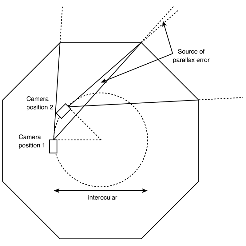
One alternative is to acquire a relatively small number of photographs from two offset cameras and combine them into a panorama using well established monoscopic panorama stitching software tools, see the following figure for the top-down view of the camera frustums for an eight camera system.
Note that two cameras necessarily violates the usual rotation about the zero parallax position of the lens. While this approach in practice can often give acceptable results, and it can be extended to video recording by employing multiple video cameras rather than a rotating rig, it does have limitations. The first issue involves parallax error, that is, between the two adjacent camera positions slightly different views of a scene object are recorded. The consequence is that a perfect stitch is not possible, noting that it is possible for a particular depth but not all depths at once. The second issue is that between adjacent camera positions one camera is closer to scene objects than the other resulting in the same effect as a change of zoom across the boundary between the cameras. The consequence as for the parallax issue is a difficulty creating a perfect stitch across the overlap zone, these errors generally reveal themselves for close objects in the scene. In practice, with sufficient overlap modern machine vision techniques can identify feature points between the cameras and form two apparently seamless panoramas. However to achieve those results these algorithms often employ local warping, this amounts to a depth distortion in those regions as well as differences between the visible scene objects, both often very noticeable when viewed in a high quality stereoscopic viewing system. The upshot are image discontinuities that are often more apparent when viewed as stereoscopic pairs compared to viewing panoramas monoscopically. Due to the recent resurgence in head mounted displays a wide range of sophisticated algorithms have been developed to address these problems, or to at least hide them. This includes seam line and image cuts along feature curves, shape interpolation, optical flow and many more. While these techniques each find applications in some situations, they are generally designed to hide the obvious image flaws which would inevitable arise. They each have situations in which they fail. The difference between the perfect ODSP and a finite number of cameras is a matter of the degree of discretisation. The authors, and others, have experimented with manual rotations of a camera in ever decreasing small stepping angles between each shot. At some stage for practical purposes one requires a motorised system, even at 3 degrees there are 120 individual camera shots per camera and if performed manually the scene is almost certainly going to change over the duration of the capture.
The size of the angular stepping depends on the degree to how narrow the parallax zone in figure 2 needs to be, and for the zoom error how close objects can be to the camera. For interior scenes tested by the authors, even 1 degree steps were not small enough. In essence both effects need to result in less than one pixel difference across the edge between adjacent image slits. At this point it was decided that manual discrete stepping was inadequate and a continuous rotating system was required, recording not still photographs but video. While not discussed further here, the possibility of recording from a single perpendicular offset camera was explored. It holds some advantages, for example, the ability to choose the interocular separation in post production and the need for a single camera saving costs and possible colour or optical differences between two cameras and lenses. In reality in order to achieve human eye separation the tangentially rotating camera needs to be further off center than for a pair of cameras. This not only introduced mechanical strains on a rotating system, it also exasperates the parallax and zoom issues discussed above. Solution
The desirable characteristics for a pair of cameras for an ODSP rig are as follows:
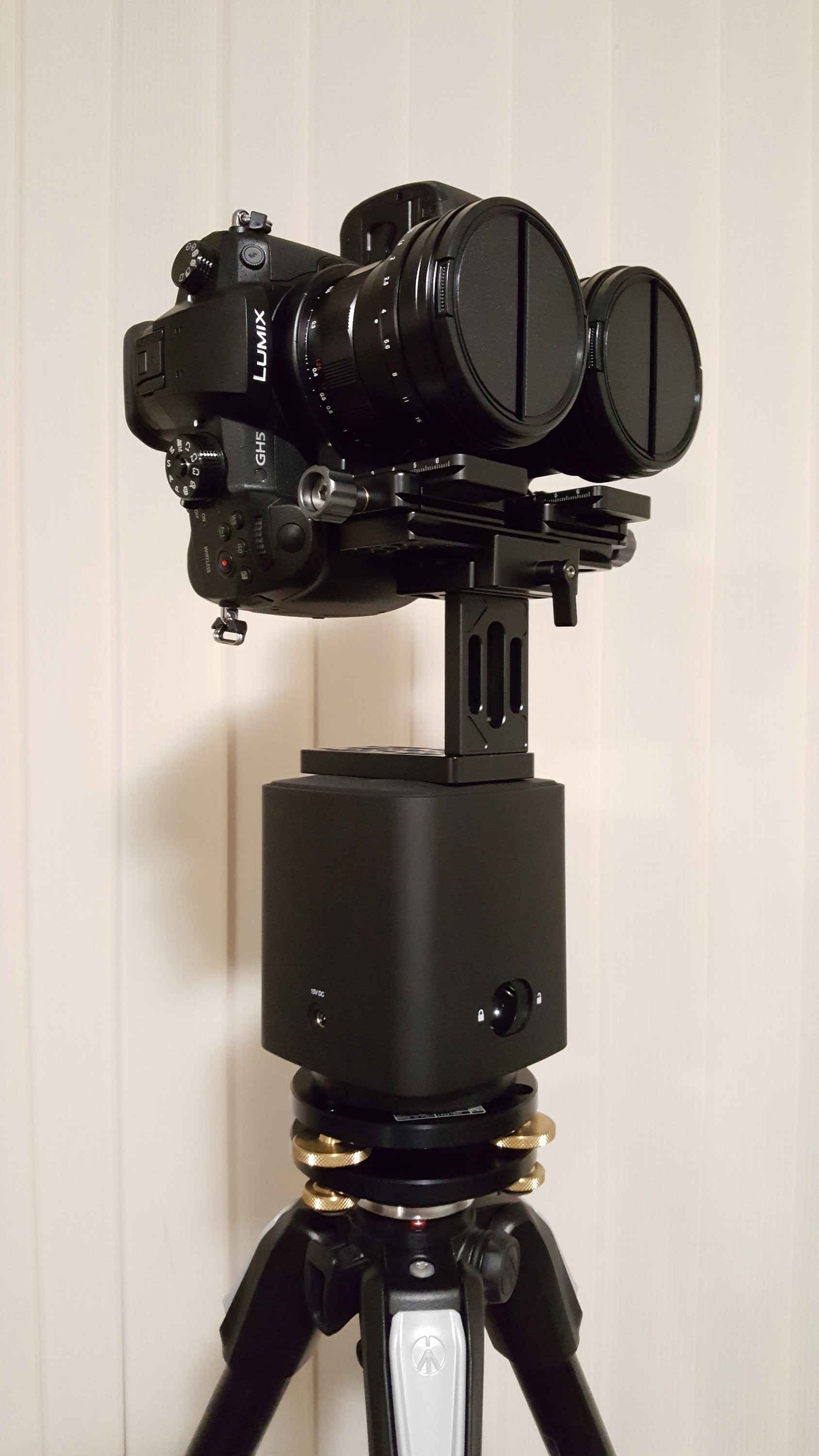
In the first quarter or 2017 Panasonic released the Lumix GH5 camera which possessed many of the desirable features listed above and making it a cost effective candidate for a high quality ODSP rig. Specifically, it was able to record at full 4K wide, at acceptable frame rates, at 10 bit and minimally compressed 4:2:2 video. The shooting modes of the Lumix GH5 relevant to this discussion are listed in the following table, only the 4K and UHD 10 bit modes with 4:2:2 compression are shown. Noting that these modes are subsequent to the firmware release in late 2017. It is therefore possible to trade-off resolution and slit width (function of frame rate) for dynamic range and image quality. The mode chosen for this work is the third hilighted row, a true 4K high sensor resolution, 24 fps, 10 bit colour and 4:2:2 compression. The next candidate would have been 29.97 fps at 3840 pixels, this would lower the panorama resolution but provide narrower slit widths. Note that the camera does support both higher resolution and higher frame rates but at the price of image depth and compression.
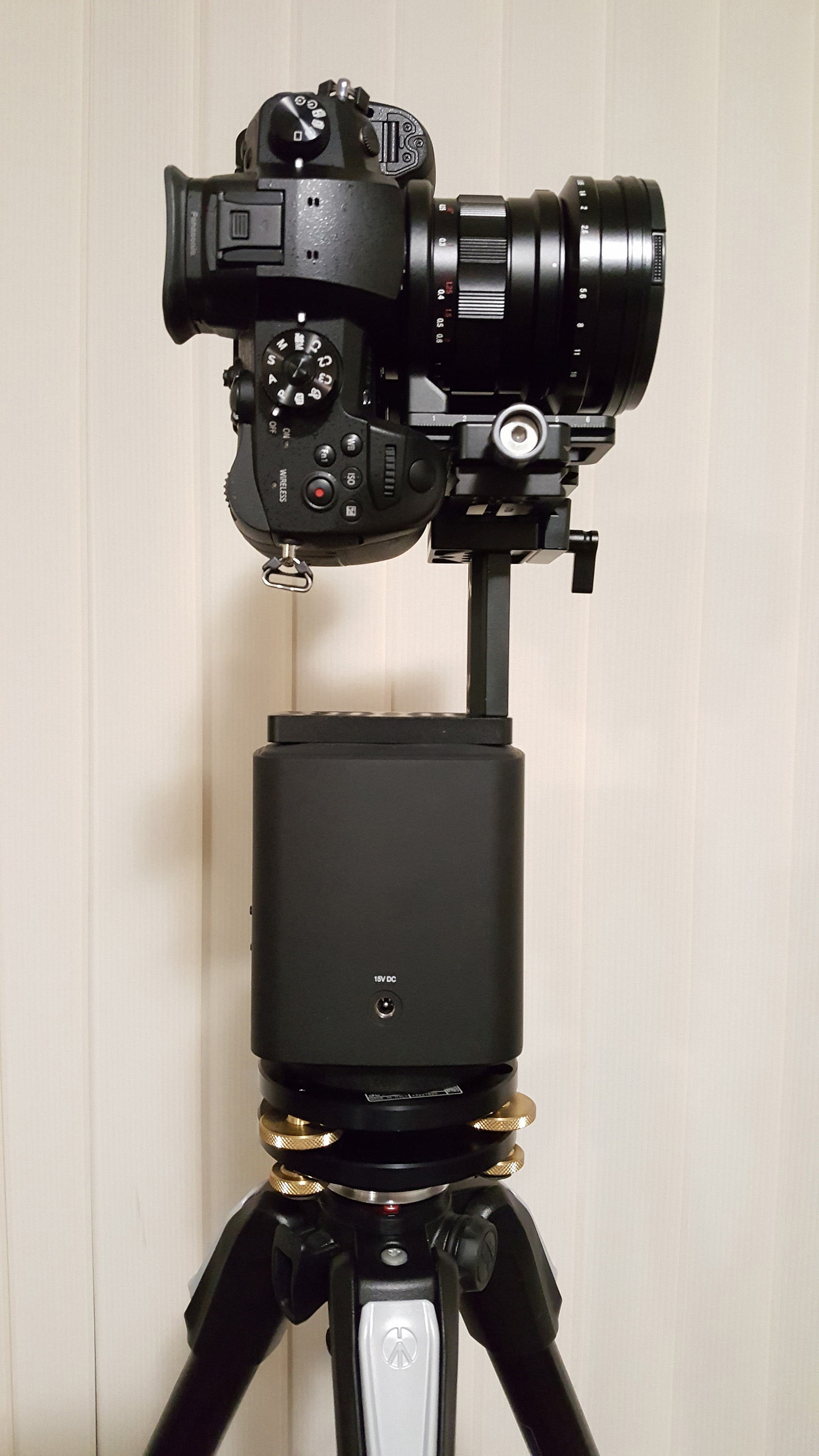
In order to achieve a 4K high panorama the cameras are orientated in portrait mode, a custom lens based clamp was engineered in order to create the minimum interocular distance possible. Consideration was given to orientating the cameras at an angle in order to increase the vertical resolution by using a diagonal slit rather than a vertical slit. This was not implemented mainly because for the aspect ratios used the gain was only a modest 15% and it considerably complicated (and possibly compromised the quality of) the post production. Implementation
Image processing
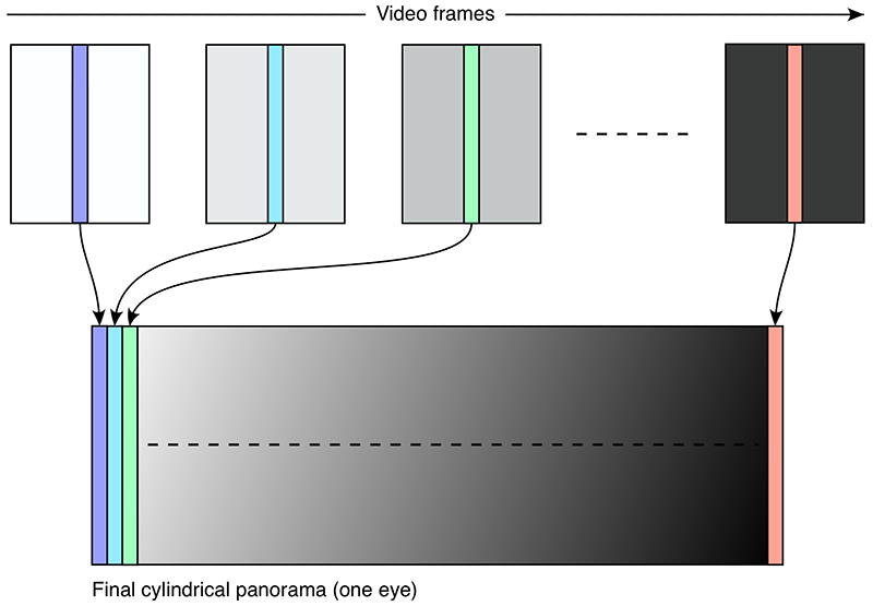
The straightforward method of forming each of the final panoramas is to simply extract slits from each video frame, assembling them literally as shown in the figure above. In practice a slightly wider slit is chosen and adjacent slits blended together across the overlap region. The horizontal field of view of a single slit hfov is given by
Where φ is the total rotation angle, T is the rotation duration and f the frames per second of the recording. The slit width w in pixels is given by 
where vfov is the vertical field of view of the lens and H the height in pixels of the frame. The following table lists typical slit widths for a selection of lenses and camera recording modes. Note that the vertical field of view may be different to that predicted theoretically since the different camera modes can use different regions of the available sensor area. This also illustrates the advantage of choosing a lens that is the least required for a particular application in order to maximise the horizontal resolution.
This direct slit approach has a number of disadvantages, one is that it makes antialiasing problematic when, for example, one wishes to map the input frames to a higher or lower resolution panorama. The other issue is that the ideal number of pixels per slit is generally not an integer, and yet only integer slits can be extracted. While this can be a minor effect for wide slits, in the work here the desire is to approximate the continuous case as much as possible so very narrow slits are used, usually between 5 and 15 pixels. The more elegant solution uses the approach employed in most image mappings, that is, one considers each pixel in the output image and estimates the best pixel from the input images. Using this algorithm antialiasing is straightforward, that is, each output pixel is supersampled with the contributing pixels from the input image averaged together. This additionally serves to increase the dynamic range of the result and naturally handles estimates close to the shared edge of slits from adjacent images.
The final resolution of the panorama is a function of the number of pixels vertically and the vertical field of view of the lens. The number of pixels vertically H is fixed depending on the sensor and shooting mode of the camera. The number of pixels horizontally W is given by 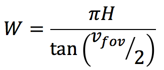
This can seem counterintuitive but the reason this arises is because the vertical field of view of the lens is spread across the available pixels vertically resulting in a certain degrees per pixel. For square pixels this dictates the number of horizontal pixels across the 360 degrees horizontally. As such narrow vertical field of view lenses result in the highest panorama resolution horizontally. This is for a cylindrical panorama, as vfov tends to 180 degrees a cylindrical panorama becomes increasing inefficient. In the same way as a perspective projection becomes increasingly streched and inefficient as the field of view approaches 180 degrees (actually around 130 degrees). For a high vertical field of view ADSP a fisheye lens is more appropriate, this is outside the scope of this discussion. The final pipeline is as follows.
Typically only the outcomes from stage (2) and (3) would be archived as the original source material. (2) so that any subsequent algorithm improvements can be reapplied to the footage. (3) so that any editing (image size, colour, zero parallax) can be reapplied. Example
References
| |||||||||||||||||||||||||||||||||||||||||||||||||||||||||||||||||||||||||||