High resolution omnidirectional stereo panorama imaging and tiled displaysWritten by Paul BourkeUnity 5 and getreal3D implementation by Nick Oliver DOI: 10.13140/RG.2.1.4212.5922 June 2015
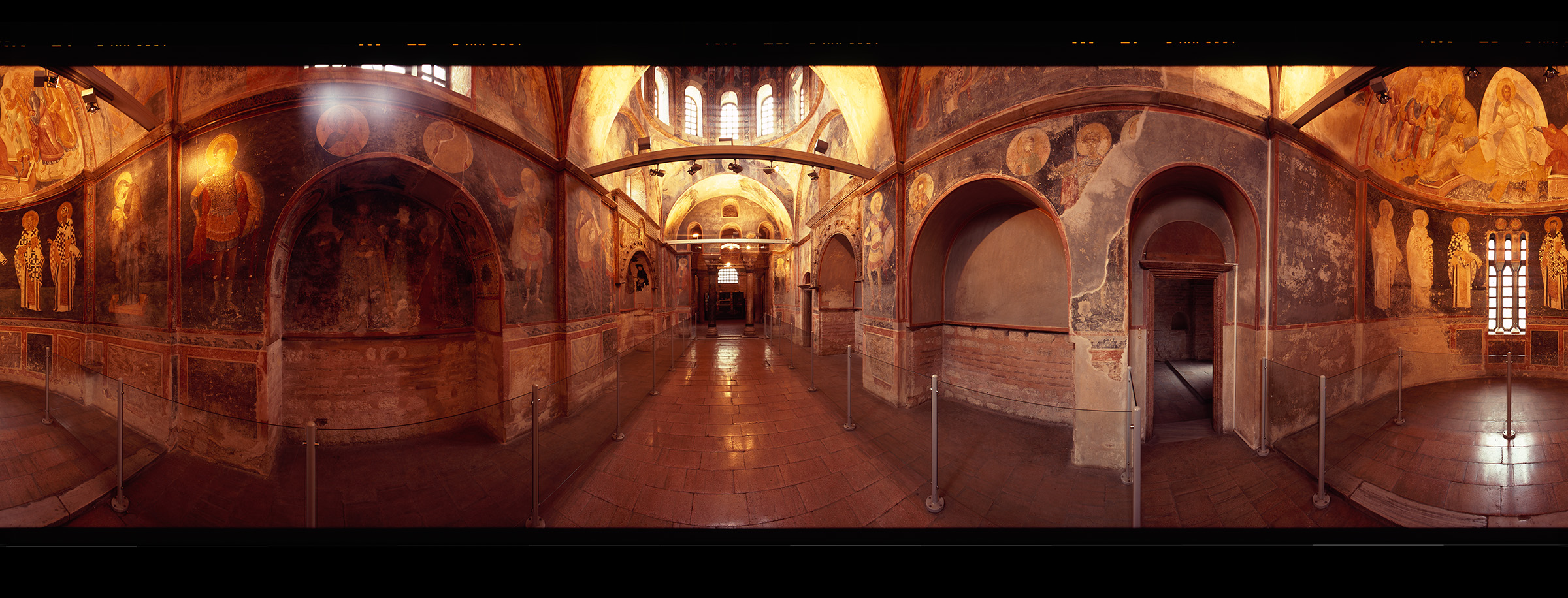
The following is an informal discussion around stereoscopic panorama photography and presentation on tiled displays. It is not intended to be an extensive survey of the field but rather some (possibly) interesting observations from a newly installed 18MPixel tiled wall at iVEC@UWA. The example imagery is based upon stereoscopic panoramas captured using the RoundShot camera (Sarah Kenderdine, Jeffrey Shaw 2010). The imagery is captured on 70mm film, drum scanned, post processed (author) to align the pairs and blend across the 0-360 degree seam, and finally cleaned to remove dirt or hairs on the film or drum scanner. 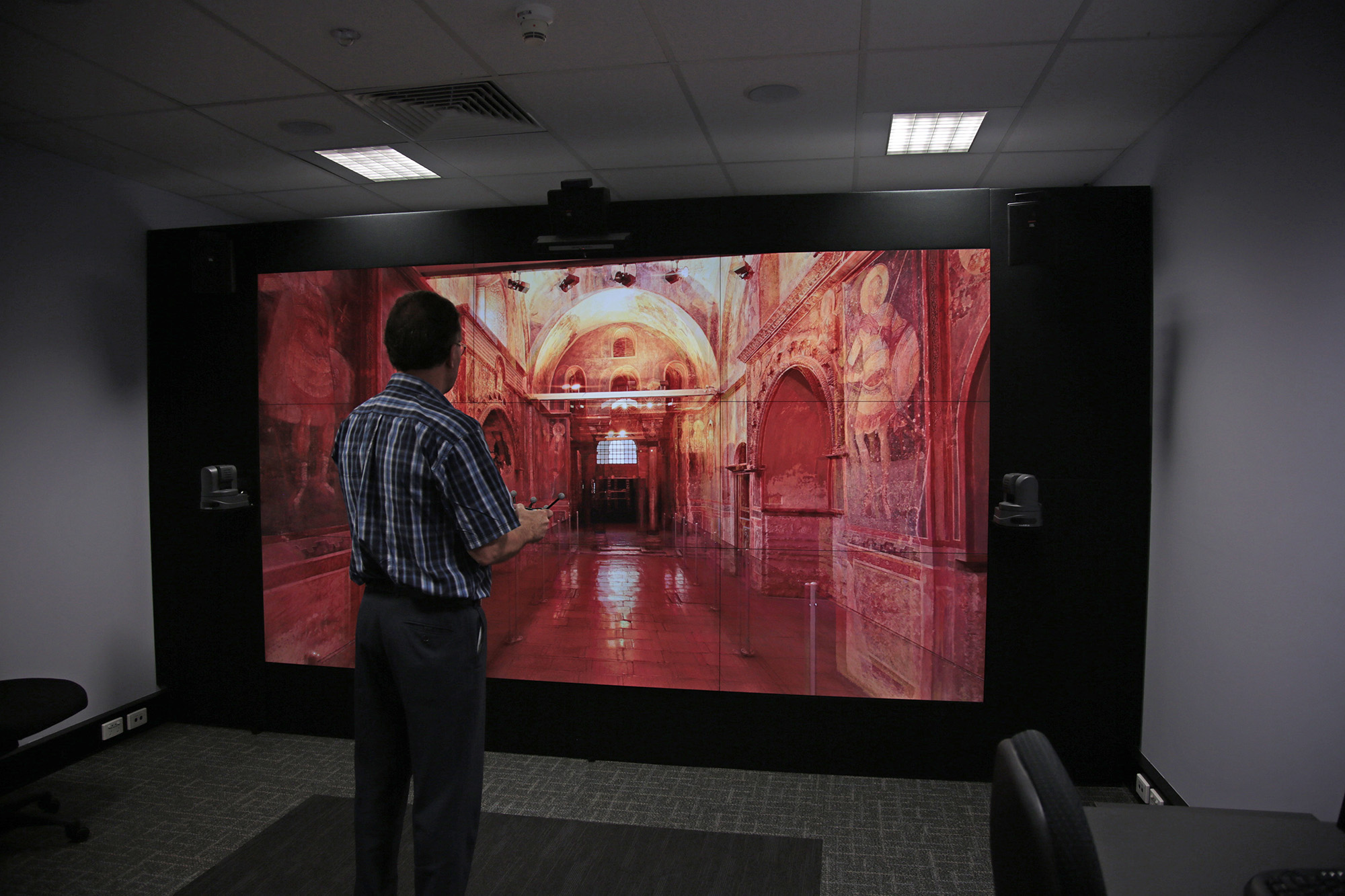 One may ask what the limiting factor is to the image fidelity. The original film was scanned to approximately 17,000 pixels across the width of the film. The resulting scans appear to be at the limit of either the film (iso noise) or the scanner used, see figure 2. The final production image pairs were reduced to approximately 8K wide in order to be a match to the proposed projector based cylindrical display system. The projection onto a cylinder involves a geometry correction (image warping) and possibly an edge blending. Even if the lens optics were perfect this results in pixels no longer being independent and a resulting "softness". As such the actual perceived resolution on screen is lower than the theoretical projected image. The display employed here is shown in figure 1 and consists of a 3x3 array of tiled Barco panels, stereoscopic 3D capable. In this case there is no geometry correction or large glass lenses and thus the difference between theoretical and perceived resolution is minimal.
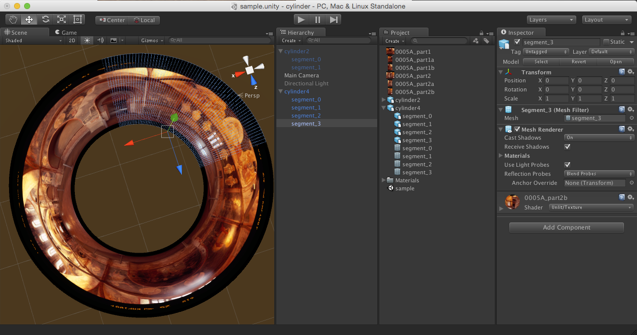
The projection parameters in figure were designed for a viewer 1.5m back from a 3m wide display. This is a field of view of 90 degrees. Since the display in question is 6000 pixels across, a matching panorama resolution would be 24,000 pixels. The original panoramas were reprocessed to 16K pixels across, the visual difference when switching between the 8K and the 16K was significant. 3D structure that was not visible in the 8K version was made apparent, for example in the roughness of surfaces or the curvature of small curved objects. This is expected since depth fidelity is dependent on having sufficient pixels to differentiate depth variation. Noting that in this case it was still the panoramas that were the limiting factor to the perceived resolution, not the display itself. This raises interesting questions on how one captures imagery for increasingly high resolution tiled displays, assuming one wishes to make full use of the available display capability. The playback solution is based upon Unity version 5 and the getreal3D software [Movie]. Two cylindrical meshes are placed around the viewer and assigned to each camera, the cameras are coincident since the stereoscopic information is encapsulated in the panoramas themselves. In Unity version 5 and assuming appropriate hardware one may assign up to an 8K texture to this mesh. So an 8K representation only requires a single cylindrical shaped mesh. The 16K version requires that each mesh is formed in two halves, each assigned half of a stereoscopic panorama for that eye, each image half being 8K. See figure 3. Similarly, a 32K resolution cylinder would require 4 meshes, one for each 90 degree quadrant and each with a 8K quarter panorama texture. 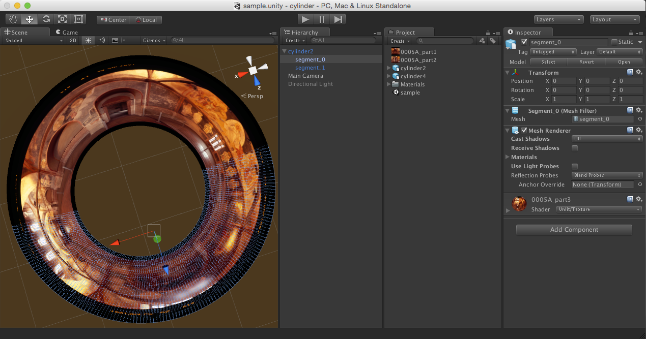
 Appendix 1: Height of cylinder Given a scene cylinder of radius "r" and a panorama of width "W" and height "H" then the height "h" of the scene cylinder is given by 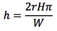
This scaling is performed in Unity, the mesh creation just creates a unit height and radius mesh. Appendix 2: Unity 5 notes
An example of two images (not full resolution) from the drum scanner are shown in figure 5. Note the overshoot in the rotational camera capture, it allows a blending to be performed across the 0-360 seam. Figure 6 shows the processed panorama pair, the alignment and blending process is automated, this includes a histogram (colour) matching between the pairs. The final panoramas would normally be further cropped to avoid viewing the film markings, alternatively the extend of the vertical panning could be constrained. 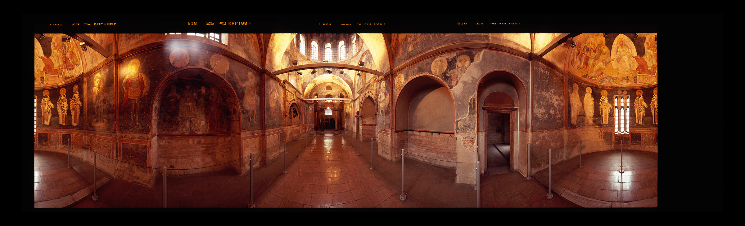

|