Creating fisheye views with the Unity3D engineWritten by Paul BourkeAugust 2011
Here I discuss a means of producing a fisheye image using the Unity3D gaming engine. The approach has been introduced here for the spherical mirror. In that case a 180 degree fisheye is generated and subsequently warped. A 180 degree field of view can be achieved with a 4 pass approach, that is, 4 renders with camera frustums passing through the vertices of a cube with the view direction towards the midpoint of the edge between the left and right faces of the cube. In the following a wider field of view is created, namely up to a maximum of 250 degrees. It is based upon the same multipass render approach except now 5 cube faces are used, left-right-top-bottom-front, and the view direction is towards the centre of the front face. The following illustrates the process. There are 5 coincident cameras, each pointing respectively left-right-top-bottom-front and each with a 90 degree field of view horizontally and vertically. Each of these camera views are rendered to a texture (requires Unity3D Pro) and each texture is then applied to the meshes found here. These meshes have been designed to create a fisheye when viewed with a orthographic camera. Given the 5 faces of the cube and the camera in the centre, the widest field of view is dictated by the angle to the corners of the side and top/bottom faces, this is approximately 250 degrees. The circular mask can be used to set a specific fisheye field of view, 240 degree in this example. 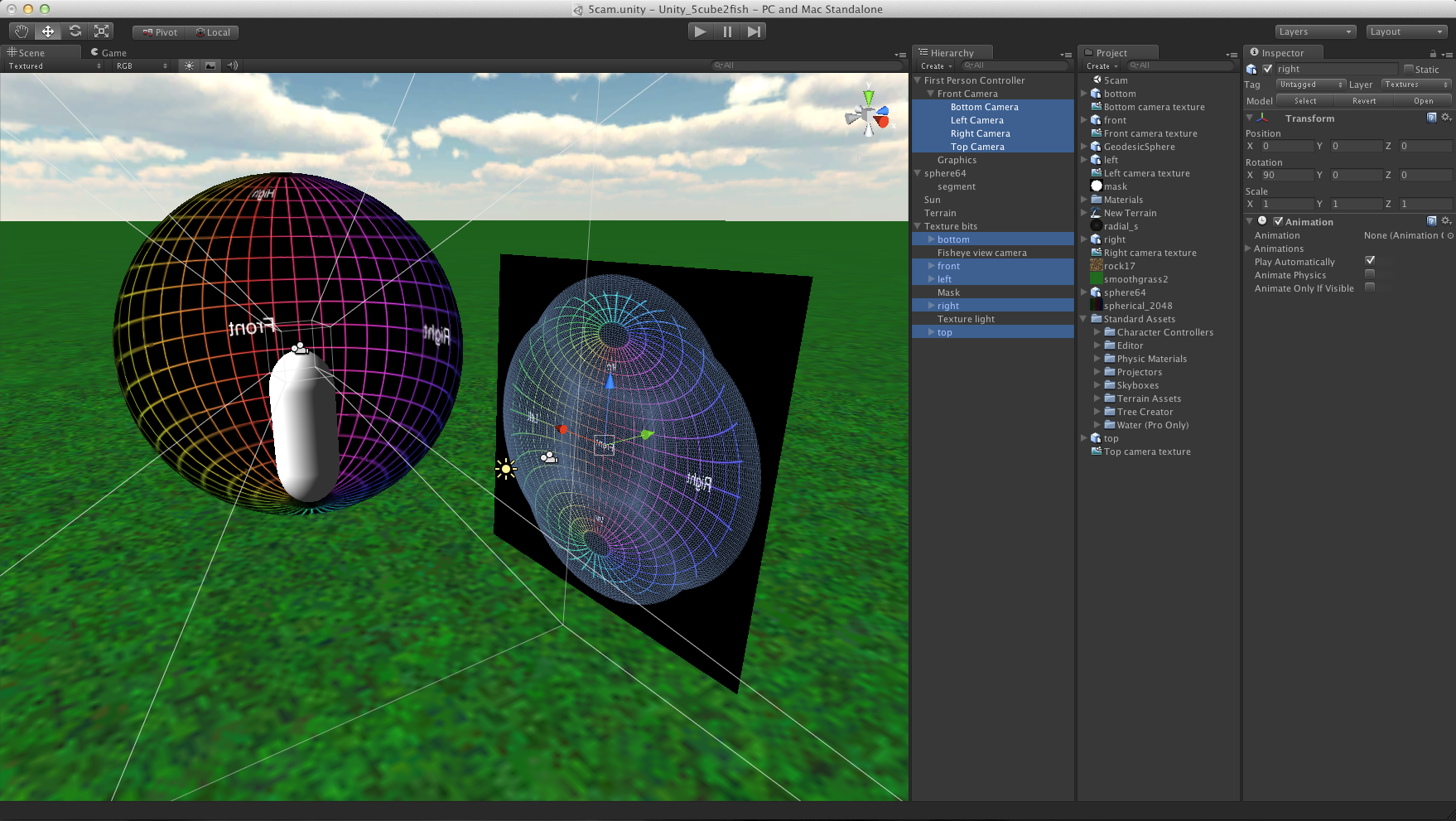
The 5 meshes with their respective camera based textures are finally viewed with an orthographic camera. To prevent this mesh structure being visible in world, the 5 meshes and light source are placed on a separate layer. Similarly the scene lights do not illuminate the meshes and the single directional light for the mesh does not illuminate the scene. The view in game with the gamer panned up 90 degrees is shown below. The lines of longitude and latitude in the textured sphere are 10 degrees apart, one can see the field of view is 240 degrees. Other angles can be achieved by changing the size/radius of the mask. 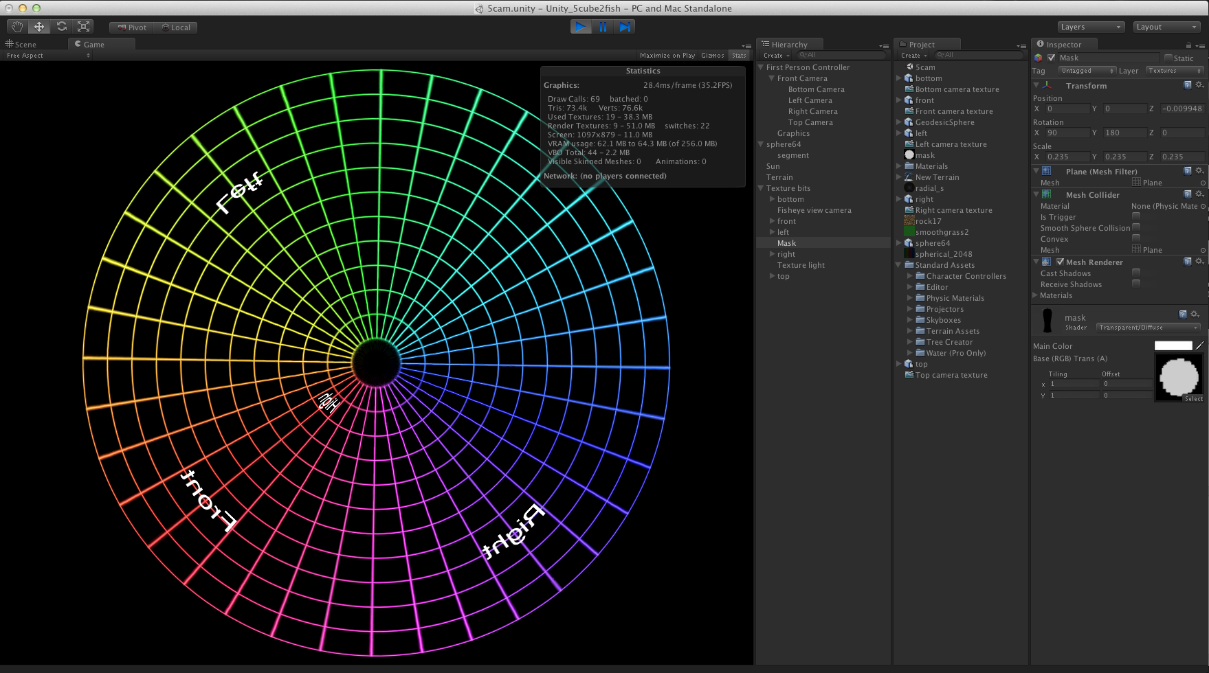
A discussion of the general technique for a 180 degree fisheye and 4 cube faces
can also be found here.
While the above is suited to a projector with a fisheye lens in a dome, there are other methods of fulldome projection. The only way to get higher resolution is to go to multiple projectors, and one option has a number of projectors around the rim of the dome. These projectors each cover overlapping regions of the dome surface, the projected imagery needs to be geometry corrected and an edge blending mask added to form a correct continuous image on the dome. There are two ways this can be achieved, the first is to do the geometry correction and blending in the software, that is, before the image is set to the graphics card. Unity can achieve this by adding a second rendering pass, transforming the image as per the earlier discussion or as per this on the iDome. The second method involves the warping and blending being applied on the graphics card, both nVidia and ATI have mechanisms that simplify this process and there are a number of interfaces developed to either manually or automatically develop the geometry/warping data. From a software perspective this is a much simpler process because one only needs to create the right rectangular viewport that the geometry/blending expects. While there are a number of ways one might create the graphics for N projectors, one convenient way is from a single computer with multiple graphics pipes. As such, the way one creates imagery from Unity is very similar to the multi-projector rig described above for fisheye except now the camera orientations and field of view are prescribed by the dome calibration system. Additionally if the projection system consists of N projectors then typically they would be arranged as a large tiled desktop in which case each virtual camera needs to be presented within each 1/N segment of that desktop. The following example should make this clear. 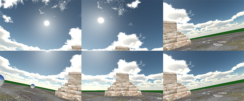
The rest is in the details. In this case consider 6 projectors, each being 1920x1200 resolution. Each virtual camera is set to render to a texture, each of those textures is then applied to a plane of the right aspect, the planes are arranged such that a final orthographic camera views them as a seamless 3x2 grid (as above). Each image above corresponds to a graphics pipe on which the warping/blending is applied. The 3x2 grid is an arbitrary choice, it could be set up as 6x1 or 2x3 and so on. 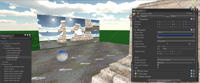 6 panels and orthographic camera in the model, but on their own invisible unlit layer Note that many camera and Unity settings need to be exactly right, in some cases for the result to work at all, in order cases to get optimal quality results.
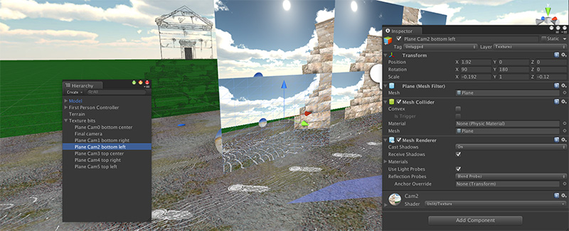 Each panel with aspect 1920:1200 positioned perfectly with its neighbours
|