iDome: Immersive gaming with the Unity game engineWritten by Paul Bourke
Proceedings of the Computer Games & Allied Technology 09 (CGAT09),
Research Publishing Services, ISBN: 978-981-08-3165-3, pp 265-272.
In many games, notably first person shooters, the player inhabits a 3D virtual world similar to the user experience in a virtual reality application or training simulator. It is generally accepted that in such environments there is a heightened sense of immersion and engagement [1] if the player is surrounded by the virtual imagery, that is, the virtual world occupies their entire visual field. However traditional realtime graphics APIs only support parallel and perspective projections, whereas for immersive displays different projections are required. In the following I will discuss a particular immersive display environment based upon a hemispherical dome and present a method of creating the correct projections using the Unity game engine [2]. Design decisions will be presented along with a discussion of the performance and issues with the approach taken. The techniques discussed are general and appropriate to other game engines for which source code is available or, as in the case of Unity, the scripting language is powerful enough to implement the required mapping and geometry correction. KeywordsImmersion, hemispherical dome, Unity game engine, peripheral vision, iDome. 1. Introduction
Over the last 20 years there have been many different immersive environments in which a user has had his/her field of view (FOV) completely occupied by the virtual world. Some of these, such as the StarCAVE [3] involve multiple planar walls surrounding the user, these were initially inspired by the CAVE [4]. Others have been based upon partial or full cylinders, examples include the full cylinder employed in the AVIE [5] and the partial cylinder of the SGI Reality Centre. A more budget version sees the cylindrical surface replaced by a number of planar walls. A third category are based upon portions of a sphere, an early example of a personal spherical display was the VisionStation by Elumens which had about a 150 degree horizontal field of view. Planetariums are an example of hemispherical environments but they are orientated in such a way that does not make them ideal for engaging in land based worlds. In the discussion here I will introduce a hemispherical dome, called the iDome [6], that is orientated to be in front of the user. The software techniques required to present a virtual world in this device are common across many immersive architectures. The impediment to using an arbitrary game in these environments is that they don't support the projections required. Typically 3D games provide a standard perspective projection with perhaps at most a 120 degree field of view and even at that limited FOV there is considerable distortion and pixel inefficiency. One solution then is to render multiple perspective views that cover a superset of the required field of view and combine these together to form the require FOV, noting that some additional image warping may be required to deal with the geometry or other details of the projection geometry [7]. 2. iDome
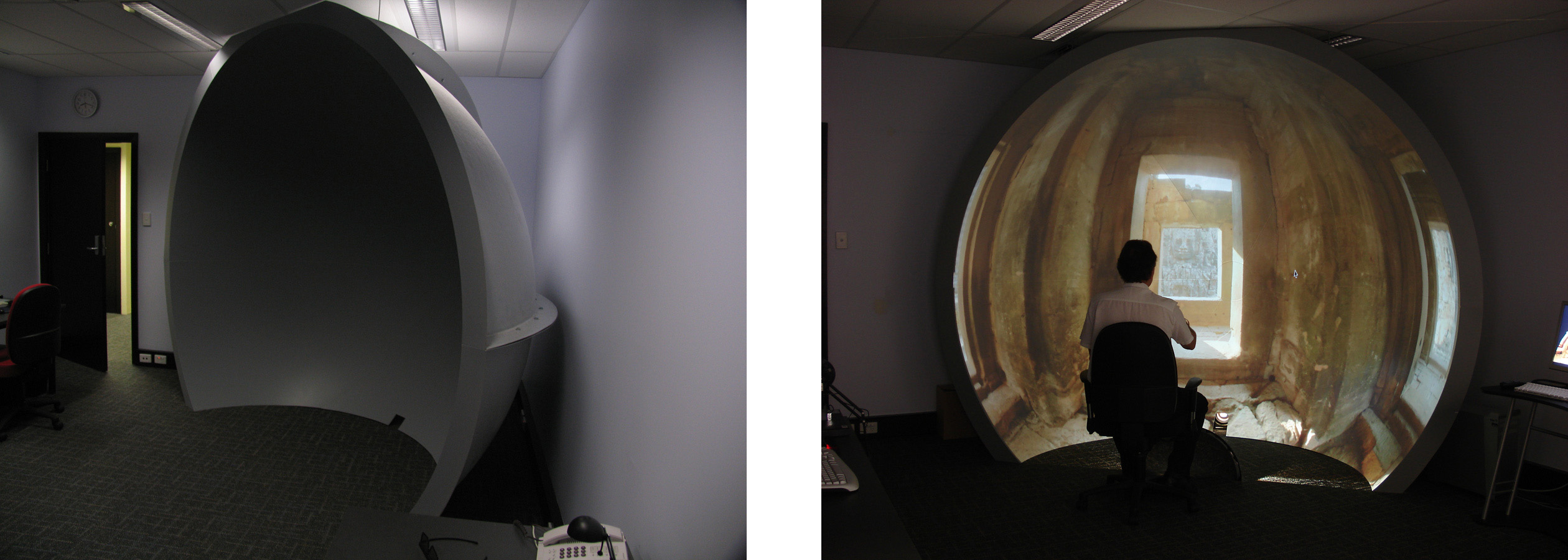
The iDome is a 3m diameter hemisphere, a full half sphere with the lower one quarter removed (180 degree field of view horizontally and 135 degree field of view vertically). The dimensions were chosen to both fit within a standard stud room (2.7m) and to ensure that a seated player has their eye level at the center of the hemisphere, see figure 1.
The physical projection is achieved with a single HD (1920x1080) projector and a first surface spherical mirror that essentially provides the light scattering required to fill the internal dome surface with a digital image. The key reason for using this approach is the unobtrusive nature of the projection hardware compared to the less complicated fisheye lens projection (of the Visionstation say) where the ideal position for the projector is competing for space with the location of the user. This projection system requires that one does not project, as perhaps expected, a fisheye image but a predistorted fisheye image, predistorted in just the right way to ensure that when the image is reflected off the mirror it appears correct and natural on the dome surface. Figure 2 illustrates the optical geometry of the system, it is this geometry that determines how the fisheye image is prewarped [7] in order to yield the correct results. The image on the right in figure 2 illustrates how an accurate calibration ensures an undistorted view on the dome. It should be noted that the image only appears undistorted for a viewer in the correct location, this "sweet spot" can be located anywhere by using a different image warping but in this case it is the center of the dome. Another advantage of the use of a single projector is that it greatly simplifies the software model compared to the multiple projector solutions to hemispherical projection [8]. 3. Algorithm
Unity is typical of the majority of games or game engines, that is, it normally runs with a single display and it generates a single perspective projection with some limited field of view, typically around 60 degrees horizontally and in extreme cases perhaps 100 degrees. The iDome requires a 180 degree field of view and this cannot be achieved with a standard perspective camera as provided directly by real time APIs such as OpenGL or Direct3D.
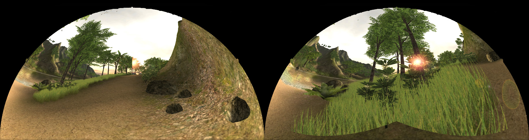
There are two ways this wider field of view can be captured. One option is to create a vertex shader that predistorts the geometry of the world in such a way that when that distorted geometry is viewed with an orthographic camera the result is a fisheye projection [9]. While the basic algorithm for such a vertex shader is relatively straightforward and has the performance advantage of only requiring a single rendering pass, the technique suffers from a significant drawback. Specifically, while the line between two points in a planar perspective projection is "straight", the line between two points in a fisheye projection is not a straight line, see examples in figure 3. The consequence of this is that lines or polygons of significant length, with respect to their projection on the fisheye image, need to be tessellated. While this is not too severe for lines where the tessellation increases the geometry load linearly, for polygons the geometric load increases by the square of the number of tessellation stages required. The optimal algorithm for this tessellation is by no means obvious since it is a function of both how close objects are to the camera and their orientation to the fisheye projection. For example a polygon may need to be tessellated differently depending on both its distance and angle to the camera. The resulting increase in geometric load not only impacts upon the number of vertices being drawn and hence the frame rate, but it is also a variable performance load depending on the relationship of the camera to the 3D geometry.
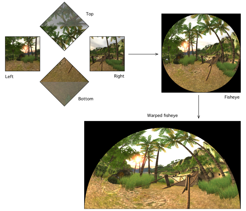
The alternative approach and the one employed here is to render multiple views (acquiring imagery across the wide field of view required) and to stitch those together to form a fisheye projection. Imagine a cube centered at the camera position and aligned such that "forward" is towards the midpoint of one of the edges. The faces of the cube define standard perspective projections each having a vertical and horizontal field of view of 90 degrees. Using this technique the minimum number of views required to form a full hemispherical display is 4, that is, the left, right, top, and bottom faces of the cube form the projection plane of the 4 view frustums. These 4 renders are applied as textures to one of 4 meshes whose texture coordinates have been designed to result is a fisheye projection.
If a fisheye lens and projector are used then there is nothing more to do. However in the projection hardware employed in the iDome (for budgetary reasons) there is an additional geometry correction that needs to be applied to this fisheye image to compensate for the distortion introduced by the spherical mirror. This is nothing more than the application of the fisheye image as a texture to a mesh, the mesh node positions and/or the texture coordinates are arranged in such a way as to create the required warped image. While outside the scope of this discussion, the exact details of this mesh are derived by considering the geometry of the projection. This calibration considers the relative positions of the dome, mirror, projector and the optical specifications of the projector to give a precise warping for a particular installation, see figure 2. In summary, there are 4 render passes to create the fisheye image followed by an additional image warping phase, this is illustrated in figure 4. Note that while one is required to render the whole top and bottom cube frustum only half of each is actually used to form the fisheye image. In terms of what is required of a gaming engine, it is essentially the ability to support render to texture and this is indeed provided in the Pro version of the Unity engine. 4. Implementation
The implementation in Unity involves a 4 camera rig, each camera directed towards the center of one face of the cube and each having a 90 degree field of view vertically and horizontally, see figure 5. Each camera is set to render to a texture and each of these textures is applied to one of 4 meshes to form a fisheye image. A 5th orthographic camera captures this fisheye image and the result is applied to the mesh that performs the geometry correction required for the spherical mirror. And finally a 6th camera, also orthographic, views this mesh and presents the result to the user. The 4 mesh pieces that create the fisheye and the mesh that performs the warping are placed on their own layers so as to be invisible to game play. The same applies to the directional lights that illuminate these meshes. 5. Discussion
The resolution of each cameras render-to-texture (cube faces and fisheye) in the multiple pass algorithm deserves some consideration. Larger textures than necessary should be avoided for performance reasons and because in general to reduce scale aliasing reasons one does not want to be scaling textures down significantly. On the other hand one wants texture dimensions to optimally exploit the capabilities of the projector since this ultimately determines the final resolution of the scene on the dome. There is also the constraint that render-to-texture textures need to be powers of 2 in each dimension. As it happens these constraints result in only one choice that is appropriate for the HD (1920x1080) projector used in the iDome. If the textures for the cubic rendering are 1024x1024 then the appropriate dimensions for the fisheye camera is 2048x2048 (almost a 1:1 mapping of pixels) for a final warping to 1920x1080 (a reasonable image reduction). There is obviously a performance penalty in the multiple pass algorithm but it is not a factor of 4 (or more) as one might expect. Table 1 gives the average results from 10 positions scattered around the Unity Island demonstration game, these timing were performed on a Mac Pro with an ATI Radeon X1900 graphics card. The variation in the rendering of the cube maps arises because in general the top and bottom cube faces render faster. Note that the Unity application for these tests was built with sync to vertical retrace enabled (limited to 60Hz), this biases the high frame rate calculations and generally underestimates them. An obvious question might be, why not remove the fisheye stage altogether and create the warped fisheye image directly from the 4 cubic maps. This has been implemented but for the sake of generality the fisheye production is retained in order to support direct fisheye lens projections systems. As seen in table 1 the performance penalty for the warping in the final stage was less than 1 frame per second.
There are some components and effects used by the Unity rendering engine that are applied as a postprocess to the frame or are sensitive to the camera view direction, these can cause errors between the seams of cubic map images. Two obvious examples relate to the sun glow and associated solar flares, another is the ground foliage that is implemented as textured planes maintained parallel to the camera. This later artifact is most commonly noticed between the bottom face and the left/right face where the camera view direction is parallel to the billboard planes. Trees in Unity do not suffer from this issue since they are full 3D objects. Conclusion
It has been shown that given sufficient control over the rendering pipeline a game engine can be "taught" to provide projections suitable for immersive displays, in this case a hemispherical dome. These same general techniques can be used for multiple wall displays, cylindrical displays, and stereoscopic projection. The multiple pass rendering algorithm for the iDome has a performance penalty factor of between 2 and 3 on the demonstration scene used but this factor has been observed across a variety of different scenes. There are some rendering effects that are dependent on the camera direction, in practice they were not objectionable and can be minimized or removed altogether by careful game design.
References [1] R. Ball, C North. The effects of peripheral vision and physical navigation on large scale visualization. ACM International Conference Proceedings Series; Vol 322. Proceedings of graphics interface 2008. ISSN:0713-5424. [2] Unity Game Engine. http://www.unity3d.com. [Online reference]. [3] Thomas A. DeFantia, Gregory Dawea , Daniel J. Sandinb,, Jurgen P. Schulzea , Peter Ottoa,, Javier Giradoc, , Falko Kuestera,, Larry Smarra, and Ramesh Rao. The StarCAVE, a third-generation CAVE and virtual reality OptIPortal. Future Generation Computer Systems, Volume 25, Issue 2, February 2009, Pages 169-178. [4] C. Cruz-Neira, D.J. Sandin, T.A. DeFanti. Surround-Screen Projection-Based Virtual Reality: The Design and Implementation of the CAVE. ACM SIGGRAPH 93 Proceedings. Anaheim, CA, pp. 135-142, August 1993. [5] AVIE: Advanced Visualisation and Interaction Environment. http://www.icinema.unsw.edu.au/projects/infra_avie.html. [Online reference]. [6] P.D.Bourke, Low Cost projection Environment for Immersive Gaming. JMM (Journal of Multimedia), ISSN: 1796-2048, Volume 3, Issue 1, 2008, pp 41-46. [7] P.D.Bourke, Using a spherical mirror for projection into immersive environments. Proceedings of the 3rd international conference on Computer graphics and interactive techniques in Australasia and South East Asia. pp 281-284. [8] D. Jo, H. Kang, G.A. Lee, W. Son. Xphere: A PC Cluster based Hemispherical Display System., IEEE VR2006 Workshop on Emerging Technologies. March 26, 2006. [9] M. Bailey, M. Clothier, and N. Gebbie, Realtime Dome Imaging and Interaction: Towards Immersive Design Environments. Proceedings of ASME 2006 International Design Engineering Technical Conference, DETC2006-99155, September 2006.
|