Interactive fisheye image generationOtherwise known as the "multipass texture" approach.See also: Geometric distortion for fisheye creation.
Written by Paul Bourke Introduction
The discussion below is a report on some proof-of-concept prototype software intended to confirm that I understood how to correctly create fisheye images using OpenGL (including off-axis fisheyes) and to evaluate the performance on mid to high end consumer level graphics hardware. There are a number of environments for which interactive/realtime fisheye projection is used, on a large scale there are planetariums, on smaller scales there are personal domes such as the VisionStation. There are existing software solutions for driving these environments interactively but they suffer from some undesirable features which this evaluation hoped to avoid. For example
The goal of this evaluation was to create a solution that should be able to be compiled on any (within reason) combination of OS and graphics card. As such the only external library required was the glut library which is almost universally supported. The goal in terms of performance was to achieve 30fps for reasonably interesting content on a modest graphics card, this would then give scope for similar frame rates of more complex scenes on higher end hardware.. Fisheye Configuration
Data projectors generally employ a 4:3 or 16:9 width to height ratio, while a fisheye image is circular. There are a number of ways of positioning and scaling the circular fisheye region on the rectangular display area, the goal is to maximize resolution and, to achieve that, sacrifices may be required. The different configurations currently supported in this prototype are shown below, the first configuration (top left) results in the projection of the entire fisheye but it uses less than 59% of the pixels. One alternative (top right) is to cut a slice from the top and bottom of the fisheye. The two examples on the bottom row were popularised by the Elumens systems such as the Visionstation. These are not full domes, in the case of the Visionstation the bottom quarter is missing. The configuration on the bottom right is for a local implementation where the Elumens projector/lens is used but operated upside down. 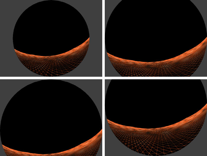
Basic Algorithm
The standard way to achieve interactive 3D graphics is by using hardware accelerated cards, usually based upon OpenGL. Unfortunately OpenGL (more accurately the algorithms it uses) only supports orthographic (parallel) and perspective projections. Perhaps the most commonly used method of creating a fisheye projection by using only perspective projections is to capture a number of perspective projections by pointing the camera in different directions about the view point and to extract the fisheye from those multiple projections. The most common approach is to render views from the center of a cube where the vertices of each face of the cube form the view frustum, the camera aperture is 90 degrees vertically and horizontally. More information on this can be found here. If all 6 faces of the cube are used as camera frustums then one can create any projection type in any direction. For a hemispherical dome it is sufficient and necessary to capture views from 4 faces of the cube, the configuration chosen here is shown below. The camera is located at the center of the cube, looking towards the middle of the far edge, the up vector bisects the upper face of the cube. 
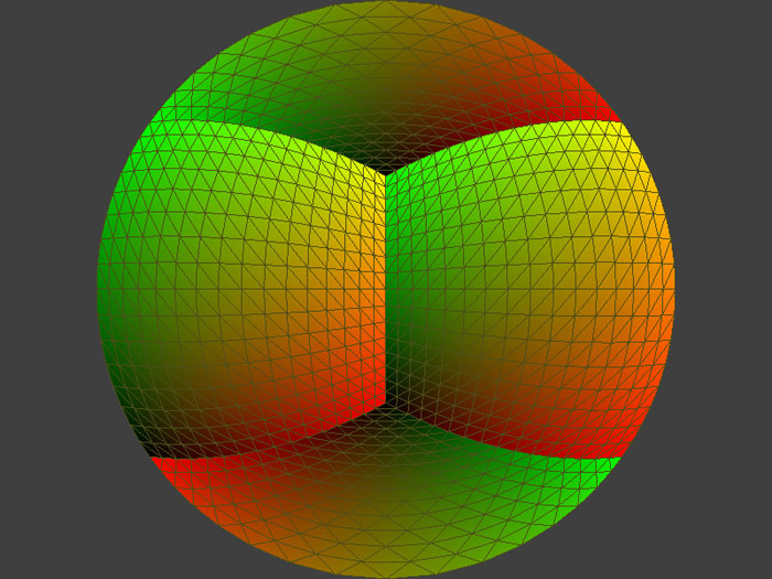
Note that for the truncated dome configurations shown above only three faces of the cube are necessary (this will be left as an exercise for the reader). If these truncated domes are being used then it is usually worth around a 25% performance improvement to use just 3 faces. Once OpenGL has been used to capture the 4 views they need to be resampled to form the fisheye. Doing this numerically would most likely be slow but once again we can use OpenGL and the high performance texture mapping most cards have. One creates a piece of texture mapped geometry constructed precisely so that when viewed with an orthographic projection a fisheye projection of the original scene results. There are many ways of doing this, the one chosen here is a flat disk tessellated as shown below. Each vertex has a precisely calculated texture coordinate. If the texture coordinates are coloured from black to red on one axis and black to green on the other then they can ve visualised as below. Note that the 4 faces of the cube, each one with its own texture map, can be readily identified.
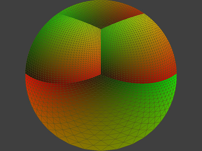
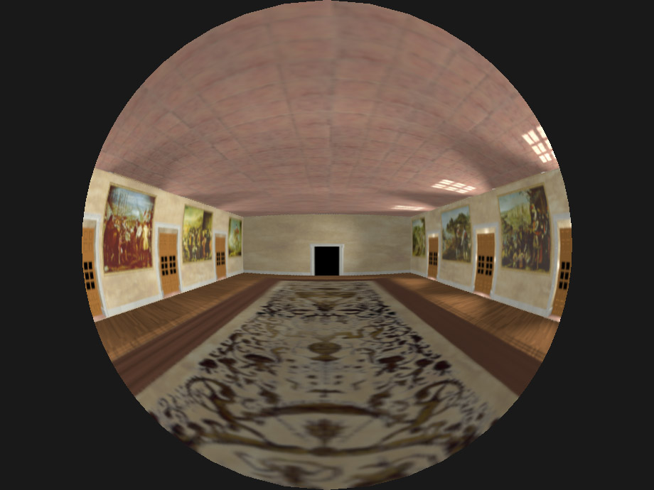
For a concrete example, the four images below (left) are the textures (rendered from the 4 separate views) shown as an unfolding of the cube. The final view after the 4 textures are applied to the flat textured disk is shown below (right).
Off-axis Fisheye Support
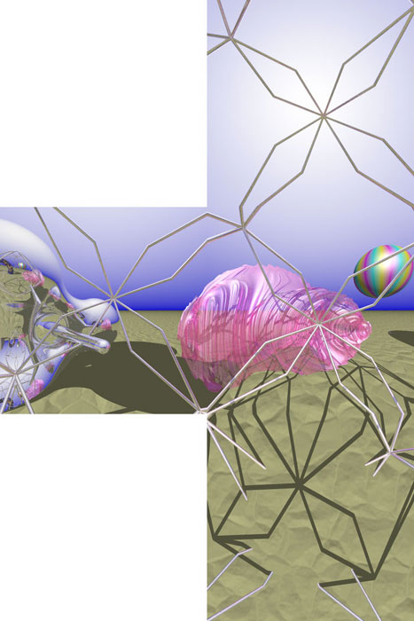
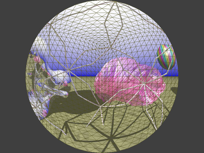
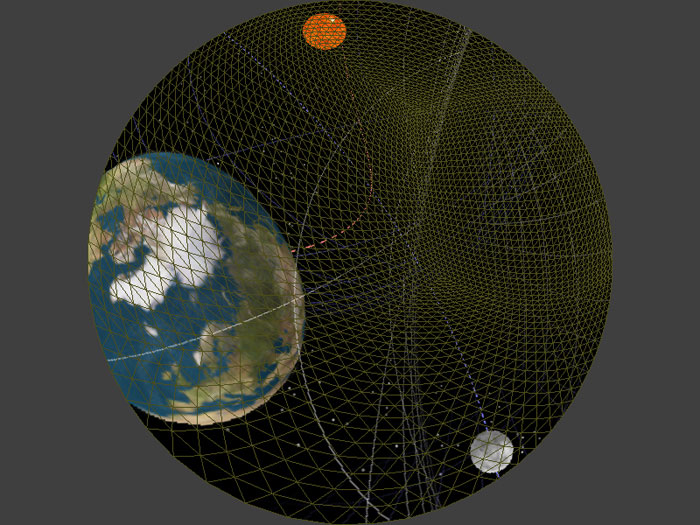
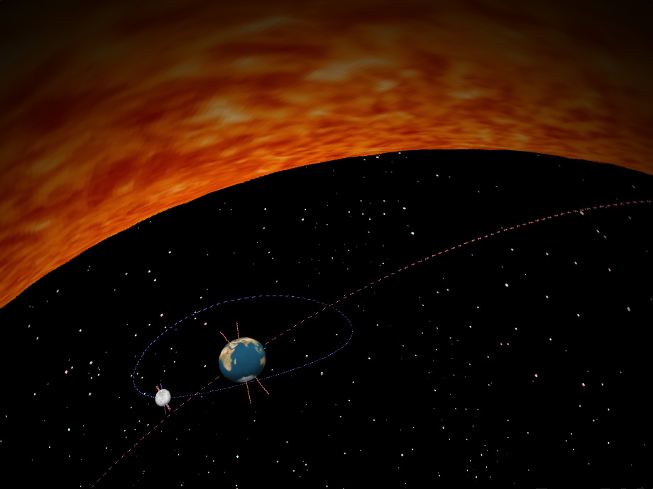
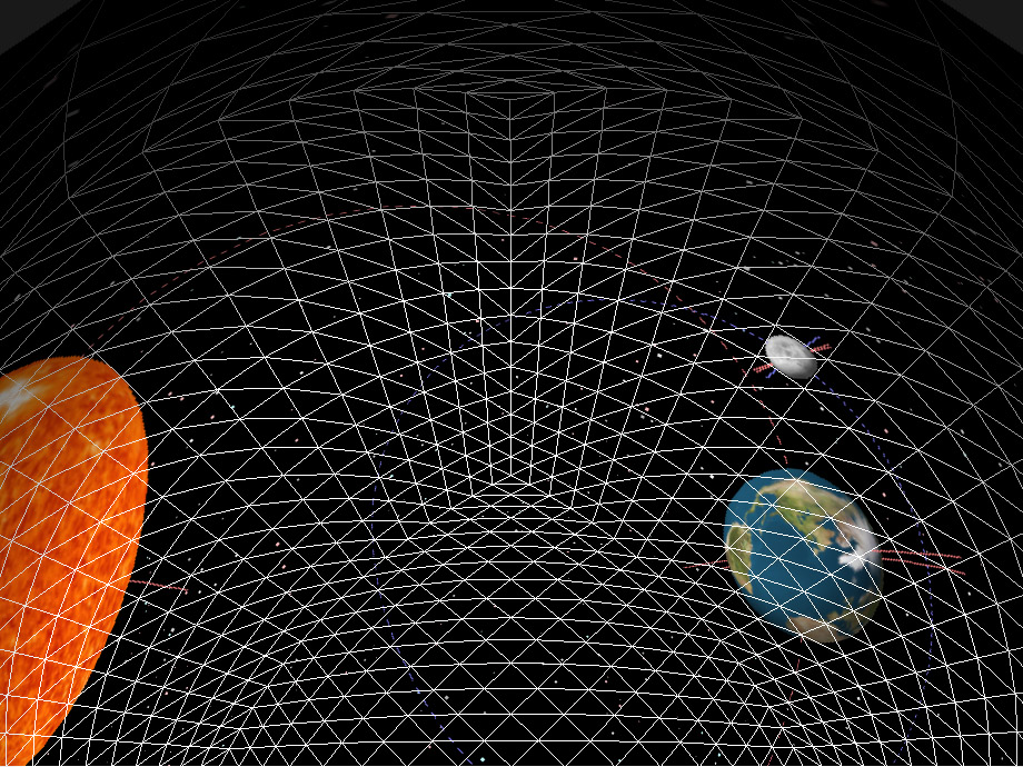
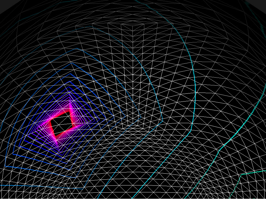
A fisheye image, projected into a dome, only looks undistorted if the observer is at the center of the dome. This is obviously not possible if the projector is also at the center of the dome. It is possible to create a distorted fisheye image so that when viewed from a particular position within the dome it will appear undistorted. This is called off-axis fisheye projection and more can be read about how they are created here. The exact distortion required can be achieved by distorting the vertices of the flat disk but leaving the texture coordinates alone. The disk mesh and texture coordinate visualisation for a observer located 60% towards the top of the dome is shown below. The most obvious consequence of this are the larger tessellated triangles, for greater offset distances the tessellation normally needs to be refined to reduce visual artefacts. Another example is given below showing some real content (gravity waves passing through a solar system simulator) and the observer half way to the right and top rim of the dome.
An off-axis fisheye projection is appropriate if there is one person in a dome or if an audience is bunched in a small region of a dome. Obviously this isn't possible for many large planetarium domes where the audience seating fills the base of the dome. Performance
From the discussion above it is clear that there are a number of processes that are occurring which will dictate the maximum frame rate that can be achieved. First the scene needs to be drawn 4 times, for each pass the back buffer is copied to a texture, lastly a simple scene consisting of the dome with 4 textures is drawn followed by a swap-buffer. The time taken to draw the OpenGL scene is of course more critical than in most other OpenGL application because it is performed 4 times for each real frame. That is not to say that there is necessarily a factor of 4 penalty, this is because display lists can usually be use and textures can stay cached. The fastest (significantly faster in some cases) way to copy the back buffer to a texture is by using glCopyTexSubImage2D(). To gauge the texture copying time one simply renders an empty scene (draw nothing except clearing the back buffer). The texture copying for a 512 square image incurred about a 0.2ms penalty. The final stage of drawing a hemisphere with the 4 textures proved not to be a limiting factor. For 512 square textures and a hemisphere tessellation with over 6000 triangles using an "average" graphics card was still only about a 0.5ms penalty. For normal operation without extreme offsets it was found that a dome tessellation of about 1500 triangles was more than adequate, using the same card this stage only incurred a 0.2ms penalty.. In summary, it is the scene drawing time that is the key determining factor for the overall frame rate. VisionStation
 Conventions
 Further examples
Update for spherical mirror projection
|