Introduction
In an earlier project I described a
multi-pass texture based algorithm by which one can create fisheye images
using OpenGL. In that approach, the scene (described by OpenGL drawing
commands) is rendered 4 times based upon frustums from the
virtual camera position to the sides of a cube.
These 4 images are used as textures mapped onto a special surface with
texture coordinates arranged so that the resulting orthographic projection
is a fisheye projection.
In what follows an alternative is discussed, namely, the
geometry is distorted in such a way that when viewed using
an orthographic projection the result is a correct fisheye image.
Which approach is most appropriate depends on the content, for example,
the former approach in general gives better results for highly textured
scenes while the later is better for crisp geometry, as is often the case
in many raw data representations.
Additional features
Besides the straightforward fisheye transformation there are some other
important features that need to be supported to cope with some features of
practical fisheye projection systems in common use.
These are given below and are all supported in the proof-of-concept
application described here.
Variable fisheye angle
Not all projector/lens arrangements are designed for a full 180 degree
fisheye.
Truncated fisheye projection
Because most projectors use a 16:9, 5:4, or 4:3 rectangular pixel array,
projecting a full fisheye (circular area within the projector rectangle) is
very inefficient in terms of the pixels used. As a result some fisheye
projection and lens arrangements truncate the fisheye, the truncated
portion of the fisheye is usually located at the back of a planetarium dome or
at the lower half of a vertical dome display such as the visionstation.
- Off-axis projection.
In order to get a perfectly undistorted view using a fisheye image it is
necessary for the projector and viewer to be located in the center of the
dome, clearly impossible. Having the projector or viewer in other positions
can be compensated for by what is called an off-axis fisheye projection. This
is critical for a personal or single person environment but it is also useful
for planetarium domes where the center of the done may be occupied by other
devices such as a star projector. Alternatively it may be that the projector
is in the centre of the dome but the center of mass of the audience seating
may be located away from the center.
Geometry tessellation
A geometric
reality of fisheye projection is that the shortest distance between
two points is not a straight line in fisheye space, like it is in a
perspective projection. So lines, triangles, and polygons that are
used to represent the model in OpenGL need to be tessellated. This greatly
increases the amount of geometry eventually passed to the graphics card
and therefore it's important to do this tessellation efficiently. The approach
tested here is to project the geometric entities into fisheye space and
recursively bisect them until the distance between points is below some
threshold. This means that short lines don't get split into many segments and
long lines that are close to being parallel to the view direction also
aren't bisected many times.
An additional option is provided where the user can control the degree of
bisection, for example, the bisection may be reduced for more demanding
models in order to trade off interactive performance with image quality.
Note that geometric attributes also need to be split on each bisection
stage. For example when splitting lines the colour (which may be different
at each end) also needs to be estimated for the new vertices. When
splitting quads, the colour, normals, and texture coordinates need to be
estimated.
This process certainly needs to be efficient and more work could be done.
For example: long thin quads should be split along the long length first.
The coordinate system conventions are given below, the camera model includes
the camera position (vp), the orientation is specified by
the view direction (vd), the up vector (vu), and right
vector (vr)....all are unit vectors and normal to each other.
The fisheye coordinates are just theta and r, or as Cartesian coordinates
(r cos(theta0, r sin(theta)) where r is proportional to phi.
The projection onto the up and right vector is found by using the dot
product with the unit vector ||p-vp||. The radius of the vector in
fisheye space is derived from the dot product of the view direction with
||p-vp||. The total expression is
x = acos(vd . ||p-vp||) (||p-vp|| . vr) / (pi/2)
z = acos(vd . ||p-vp||) (||p-vp|| . vu) / (pi/2)
Modifications to this to support off-axis projection involve adding the
off-axis vector to the unit vector ||p-vp||. The modification to support
smaller fisheye angles is to divide the acos() term by the fisheye
angle rather than pi/2. A sensible depth is required so OpenGL can
deal with z-buffer depth occlusion, a suitable depth is the projection
onto the view direction (vd).
After the geometry has been transformed, it is viewed with an orthographic
projection. Geometry below the rim of the hemisphere will have a negative
depth (y, as calculated above)
and can be removed as such and not passed onto the graphics card,
or drawn and let them be pruned by OpenGL with an appropriate use
of a near cutting plane.
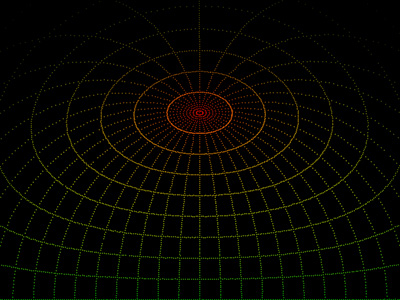
| |
Test pattern for checking any distortion on the dome.
Support for truncated fisheye projection.
Star field and resolution tests.
Control of tessellation precision.
Off-axis compensation.
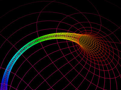
Ring tunnel (animation).
Toroidal tunnel (Animation).
Rain/meteors (Animation).
Test hardware
Hal1200, elumenati projector/lens
The testing of these algorithms was initially
performed using an elumenati projector
in a 10m planetarium dome located in Wollongong, Australia. Parallel testing
was performed in an Elumens visionstation.
|