Creating content for a full dome SkySkan show
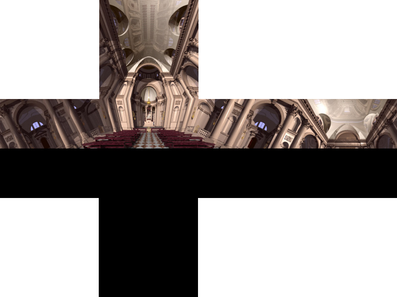
Introduction This note describes how material can be rendered and presented for the SkySkan full dome projection environments. The basic approach is that one needs to create 5 views of the scene each with a camera aperture of 90 degrees and each exactly at 90 degrees to each other, these views are called front, left, right, top, and back. This note will be concentrating on creating material from computer based rendering software and not photographically although the concepts are the same. The 5 images are processed by SkySkan to form a single "master" image, essentially an angular fisheye image (some rendering applications can create these directly). This master is then sliced up and sent to the projectors in different ways depending on the geometry of the particular dome. For example, the same master can be used to create a show for a partial dome as well as for a full dome. Image ConventionsMost camera models for computer based rendering applications require that the camera aperture, view direction, up vector, and right vector are specified. The camera aperture for each view is 90 degrees, the following diagram illustrates how the views are orientated. The great beauty of creating images in this format is that almost any rendering package can be used. At the time of writing the images need to have their dimensions an integer multiple of 100 pixels. Low resolution images are around 800 pixels square, high resolution images are considered to be around the 2000 pixels square.  Strictly speaking the bottom half of the left, right, back, and front don't need to be rendered, the images still need to be square but the bottom half can contain anything since it won't used to make the fisheye master. So the example below
Could be submitted as follows with the corresponding reduction (2/5) in the render times. Unfortunately not all packages automatically render half frames, there are solutions to this restriction but they vary between packages and generally require some additional external programming. 
This example also clearly illustrates that this is not a particularly useful view for full dome projection, unless one was interested in the ceiling. Commonly the front view vector is orientated down from what would normally considered the front, the result is that the front view center is raised above the spring line of the dome.
Usage: tga2dome filename n size [options]
       filename must be of the form [l,r,t,b,f]_name_nnnnn.tga
       n        is the sequence number, see filename above
       size     is the width and height of the input images
Options
       -w n     sets the output image size to n, default = 2 * size
       -a n     sets antialiasing level to n, default = 1 (none)
       -vp x y  sets the view position (x,y) for offaxis fisheye
       -o s     overlay with the tga file "s" (expects alpha channel)
File name conventions
The file naming convention is of the following form: c_s_nnnnn.ext
So for example,
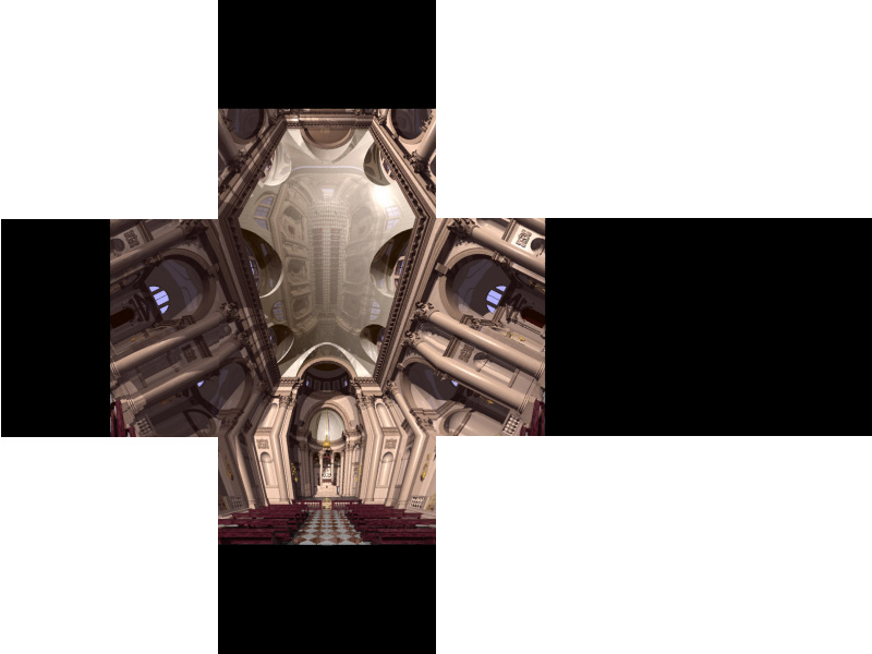
the first frame from an animation sequence called "starmap" might be called Previewing the images without a dome or projection system is an interesting exercise. One straightforward approach is to create a composite image made up out of the 5 pieces, some examples of these can be seen in the examples section below.
One alternative to previewing these images is to place oneself in a
cube and map the 5 images onto the sides. An example of this was created
in OpenGL, the user can interactively move about a simple scene but instead
of looking at the scene he/she is looking at the images mapped onto the
cube. An helpful extension is to open the cube a little or place it
flat. Some screen shots from
examples are shown below, the source code
for this demos is available here:
skyvision.c and
skyvision.h
Usage: skyvision [-h] [-c]
          -h   this text
          -c   show construction lines
Key Strokes
           c   toggle construction lines
           q   quit
Model space
  arrow keys   rotate left/right/up/down
  left mouse   rotate left/right/up/down
middle mouse   roll clockwise and anticlockwise
           i   translate up
           k   translate down
           j   translate left
           l   translate right
           [   roll clockwise
           ]   roll anti clockwise
Projection space
         +.-   move camera forward/backwards
Further Examples
Warnings
The inverse operation is clearly possible, that is, converting an angular fisheye image into as much of the 6 cubic maps as is provided by the fisheye.  Input fisheye image: redentore.tga
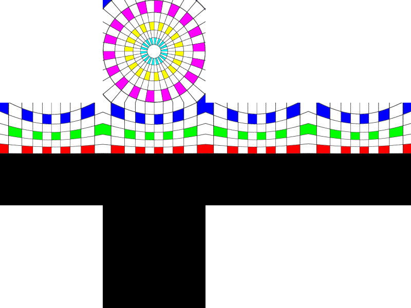
Usage: dome2cube [options] fisheyeimage
Options
   -w n   output image size, default: fisheyewidth/4
   -a n   antialiasing level, default: 1 (none)
   -x n   rotate dome by n degrees, default: 0
Test Pattern
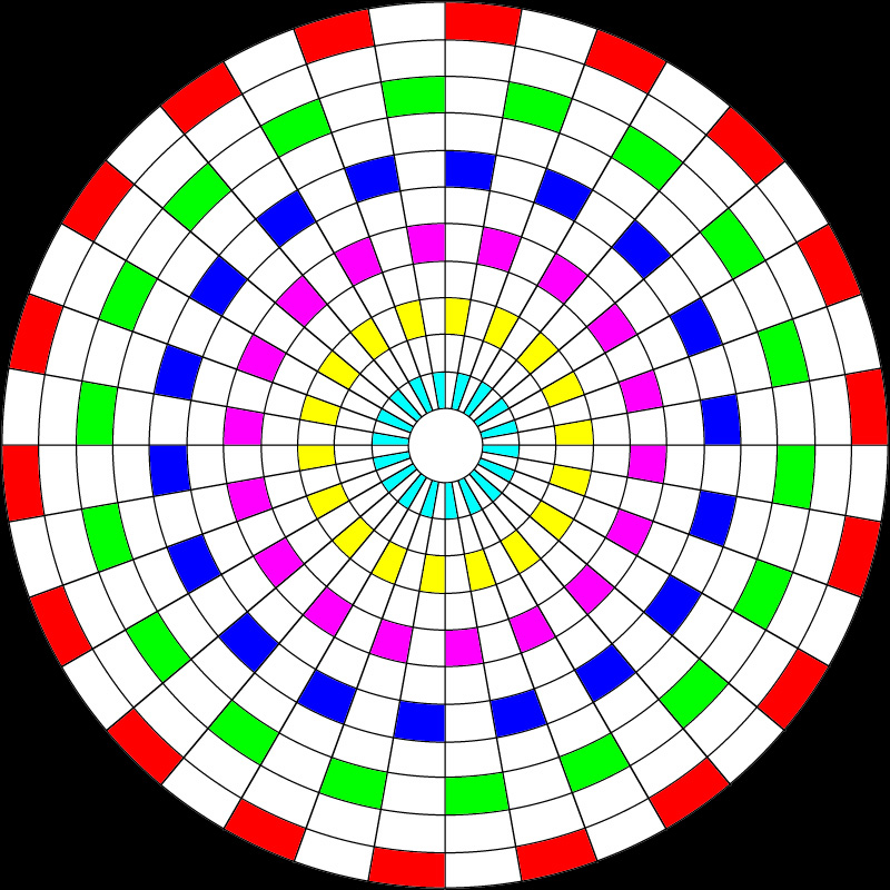 Test pattern
|