Stereoscopic filmingAchieving an accurate sense of depth and scaleWritten by Paul BourkeOct 2008
In the following I discuss, by way of an example, the process of filming stereoscopically and preparing the resulting material for viewing. Of particular emphasis for this application was to achieve a true sense of scale and depth of the filmed material, this requires a certain rigour not normally required for many applications that require stereoscopic filming. Please note that there are alternative ways of achieving the same results outlined here, this serves primarily as documentation of what needs to be achieved and the work-flow employed by the author on a particular stereoscopic filming project and using the Final Cut Pro editing software. Key geometric considerations
The key to achieving a correct sense of scale and depth in any stereoscopic content is to match the viewing geometry with the camera geometry. For content that is world scale and observed by a human, this means matching the frustums of the recording cameras to the frustums (one for each eye) of the observer to the eventual stereoscopic projection environment. The key parameters are: the interocular distance of the human viewer, the geometry of the viewer with respect to the viewing screen (assuming a single flat display here), and the field of view the viewer sees through the display rectangle. 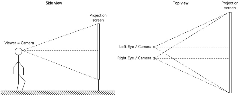
Only by careful matching the recording geometry with the viewing geometry can a correct sense of scale and depth be achieved. Similarly, when viewing any stereoscopic content the correct or intended depth and scale is only correct when viewed from a single position, all other positions involve some distortion. As one moves towards or away from the correct position a depth error occurs (depth is stretched or compressed) and a scale error occurs mainly arising from field of view changes. As one moves left-right-up-down from the correct viewing position the error involves a shearing of space. To illustrate this consider stereo footage captured for an observer at position 1, if the observer moves to position 2 the depth in the scene will appear to compress in depth. 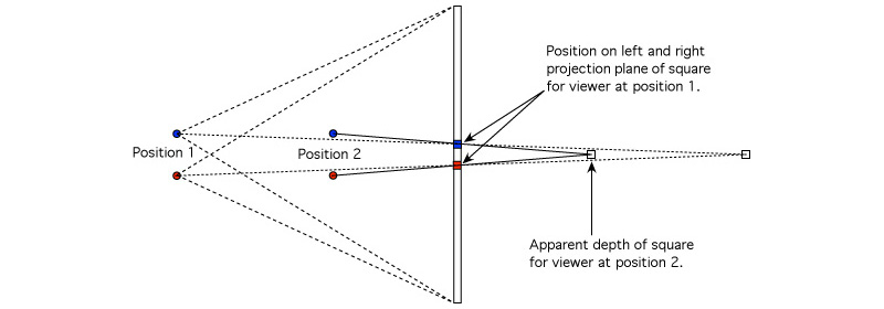
Note that in realtime generation of stereoscopic pairs the above problem can be solved with head tracking, ensuring the correct frustums are always created. With filmed material this luxury does not exist. The distortion effects mentioned above are easy to verify in a non-head tracked stereoscopic system by moving around and observing the shearing effects that result. Camera rig
As discussed above ideally the cameras would be separated by human eye separation, namely 6.5cm (on average for an adult). The cameras are aligned parallel, this is the correct approach rather than toe-in cameras. Desirable characteristics of the camera rig include good levelling and the ability to be able to lock the cameras to a base that moves along a track in such a way that the cameras can be moved and replaced without destroying alignment (generally best performed in a controlled environment rather than in the field). The cameras at least need to be slid along the railing in order to access the display of the right camera for zoom setting (see later). 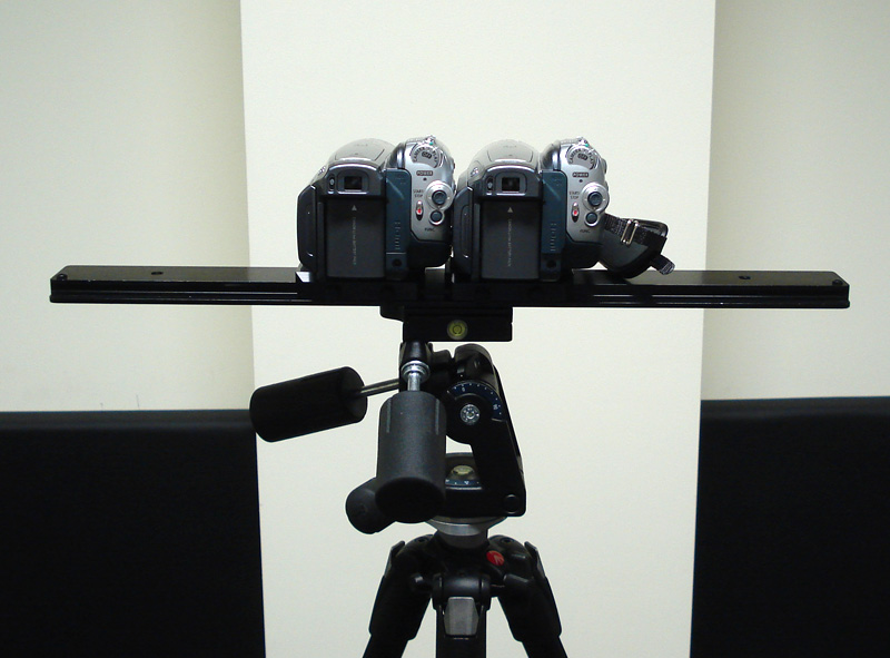
The video cameras used here are HD resolution, namely 1080p. Even though the playback system is a 4x3 aspect, 16x9 aspect for filming has an important advantage, namely it provides plenty of horizontal movement for sliding the image in order to align zero parallax correctly (see later). The key requirement for the bar that holds the cameras is that it has a good levelling bubble, the tripod needs to be relatively stable in order for this levelling to be persistent across the filming session. The cameras need to be aligned parallel to each other, one way to do this is to film a test grid pattern. If the horizontal and vertical lines are parallel to the image frame in both cameras and parallel to each other then the cameras are both perpendicular to the wall and parallel to each other. 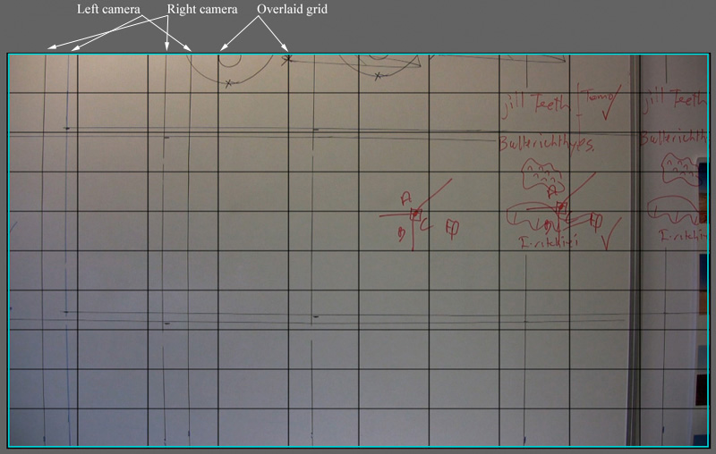
A last note on cameras ... colour and brightness matching between cameras is important, in addition it should be noted that cameras can have their sensors positioned slightly differently with respect to the lens. This can be observed by noting the vertical offset of the horizontal lines in the above image. This matching can best be achieved by finding the best pair of cameras from a collection of 3 or 4 cameras, assuming you have a friendly camera shop. Before shooting a manual white balance should be performed with both cameras. While CCD offsets and small zoom differences can be compensated for in post production (see below), colour differences are significantly more time consuming and problematic to fix. Note also the barrel distortion in the above vertical and horizontal alignment lines. This is a natural (normal) attribute of a lens, if necessary it can be corrected for in post production. Such correction is quite common if the content is going to be composited with computer generated material, it won't be considered here. Configuring FinalCutPro
While one may initially create a video capture sequence that matches the camera specifications, the editing for the final display should be performed at least at the aspect ratio of the final stereoscopic display system, in this case 4x3. The resolution of the final stereo footage may be chosen higher in order to support higher resolution displays, in this case it is set to the native resolution of the projectors being employed, namely XGA. This footage will for ever remain in the progressive digital domain and while more lossy codecs may be used in the future, for the initial cut an essentially lossless compression is chosen (Photo-JPEG). For this project a key-frame (time independent) codec is also required because the footage needs to be precisely positioned and paused. The key sequence settings for FinalCutPro are shown below. 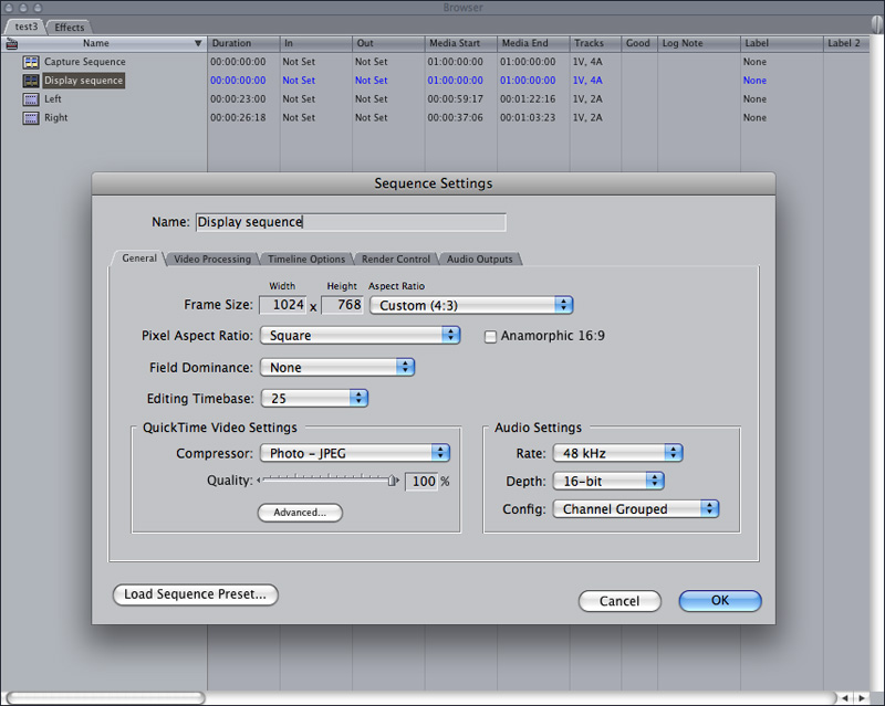
Alignment in time
The first process is to align the two streams in time, this arises because gen-locking the cameras usually isn't supported with small commodity video cameras. Given a 25p capture using the cameras used here, the two streams can be aligned to within half a frame, namely 1/50 second, this has proven adequate to date. What one looks for is a sharp event in time, either something that occurs naturally in the content or by the use of a clapper board at the start of each filming run. In the following case the fast action of swatting a fly was used as the alignment timing event. Due this time alignment some post processing saving can be incurred by filming long continuous sessions rather than many shorter clips, each of which then requires a separate time alignment process. 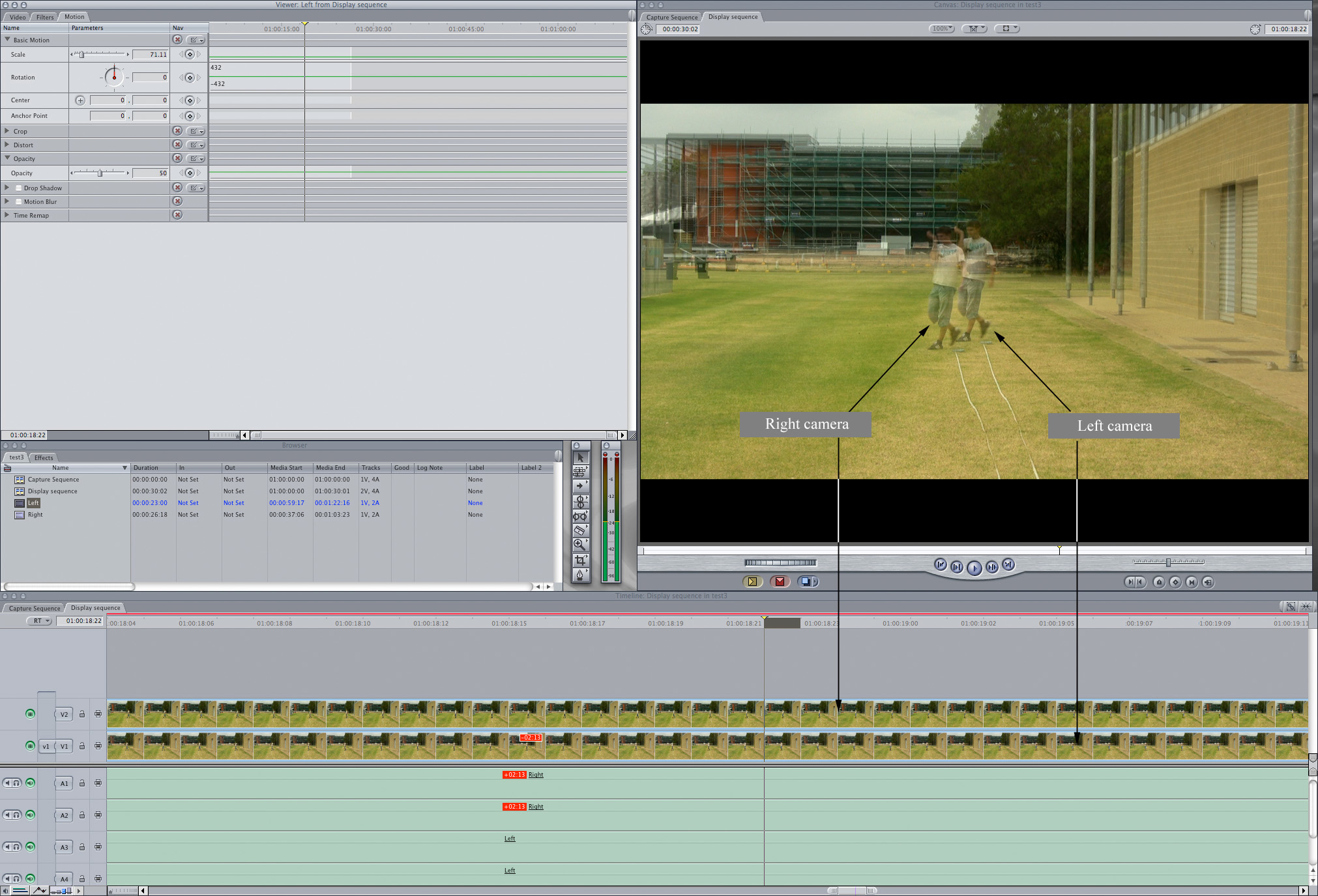
Alignment of images in the plane
As discussed above, in order to achieve a correct sense of scale and depth the camera needs to be placed, in relation to the screen, the same as the viewers relationship to the screen. This not only locks in the distance to zero parallax but also the field of view of the camera, which should match the frustum from the eventual viewers eyes to the corners of the stereo screen frame. To facilitate this a frame is built with crossbars that match the height of the lower and upper edge of the eventual viewing screen. This frame is videoed by itself for a short period before each stereo filming session. The next stage of the processing of the two streams is to scale and translate the streams such that the horizontal crossbars fill the field of view and translate the streams horizontally so that the bar is at zero parallax. After this process, all pairs of objects should only exhibit horizontal parallax, that is, no vertical parallax. 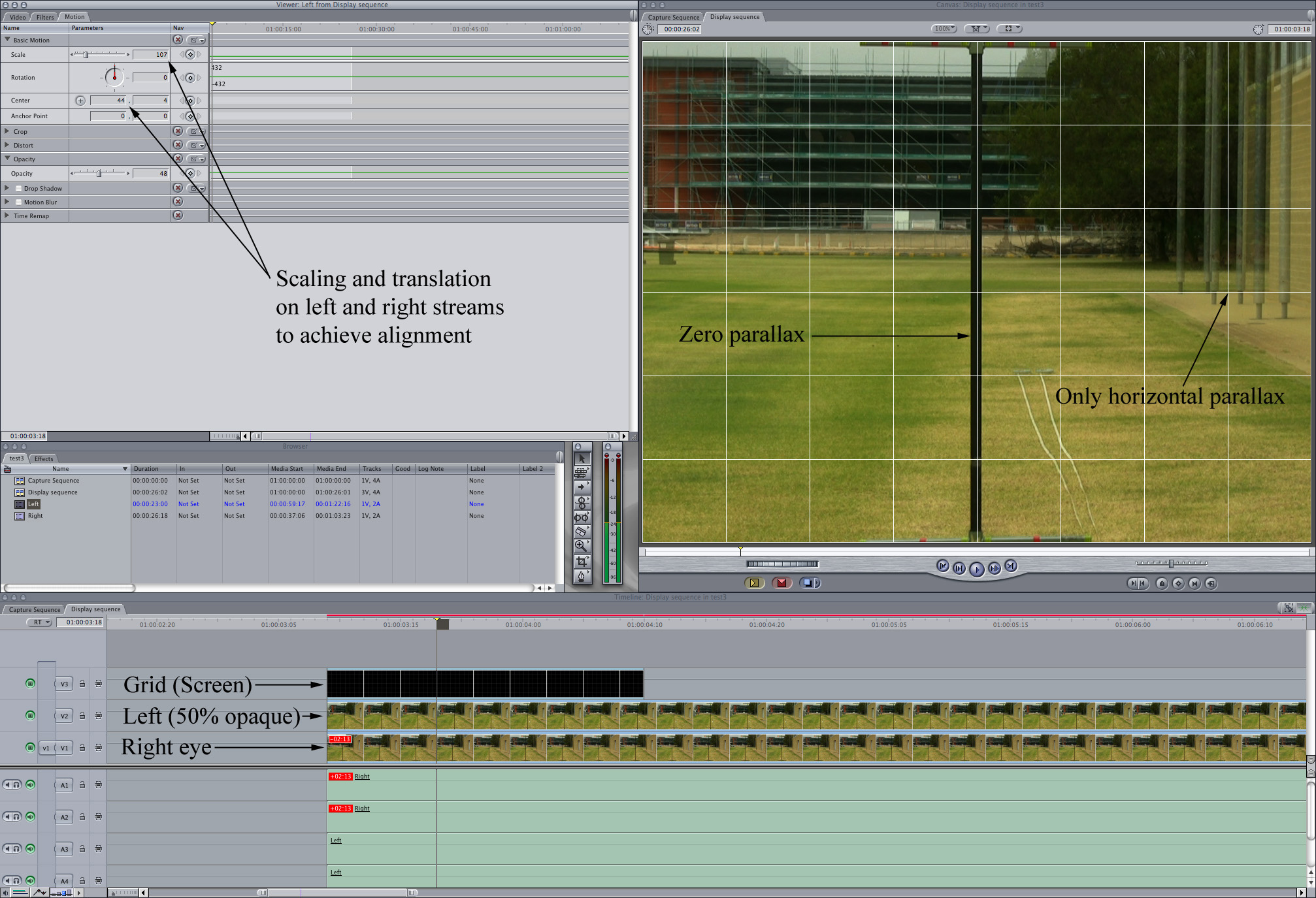
Export of streams and combining them in QuickTime Pro
The stereoscopic playback system used in this exercise is fairly standard for polaroid based stereo based upon two projectors and the footage is played back as standard movies of either double the width or double the height. In the example here double width movie frames will be created, the left eye image on the left half of the frame and right eye image on the right half. 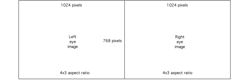
This has the advantage of being played back using standard QuickTime Pro on a double width display created with something like the Matrox dual-head-2-go. Or using software such as warpplayer to play across dual displays formed with a dual head graphics card (note that warpplayer also has improved performance over QuickTime Pro and has the ability to support a software alignment). The choice here is to export the left and right eye streams individually and combine them into the correct format for playback as a separate exercise. 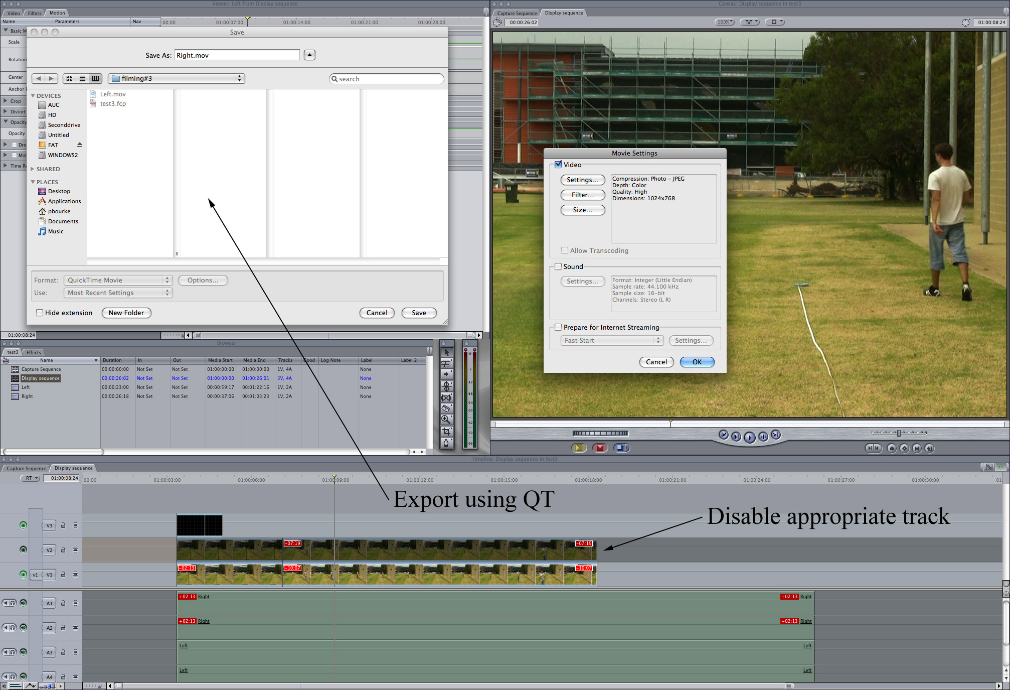
An alternative approach is to position the two streams side by side in FCP in a new sequence with twice the width of each eye stream. However this requires setting up exact crops horizontally on each stream. Much simpler is to save each stream separately and combine them using QuickTime Pro and the "offset" option after coping and "Add to movie" (Edit menu) of one stream into the other. Keeping the two streams separate and saving them as the master copies generally makes creating formats for alternative projection solutions in the future easier. For example, in some cases higher performance playback can be achieved with a top/bottom arrangement of the two streams. 
Playback
The system employed here is a linear polaroid based projection system. In reality from a content creation perspective it matters little whether it is linear polaroid, circular polaroid, shutter glasses, or Infitec. If all has worked correctly the view through the stereo projection window will appear identical to the view through a similar rectangle in the real world filming environment. The distance to moderately distant objects is one depth cue that is easy to judge. Another key depth cue for testing the success is the ground plane, it should appear consistent with the real floor in front of the projection screen. 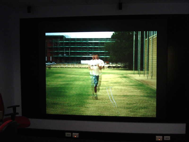
Small scale stereoscopic photographyWritten by Paul BourkeSeptember 2009
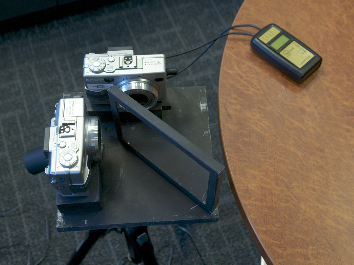
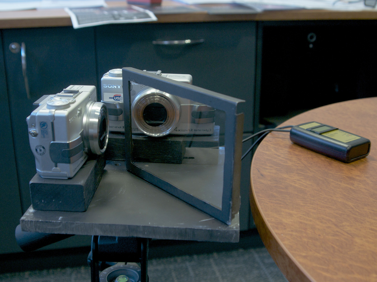
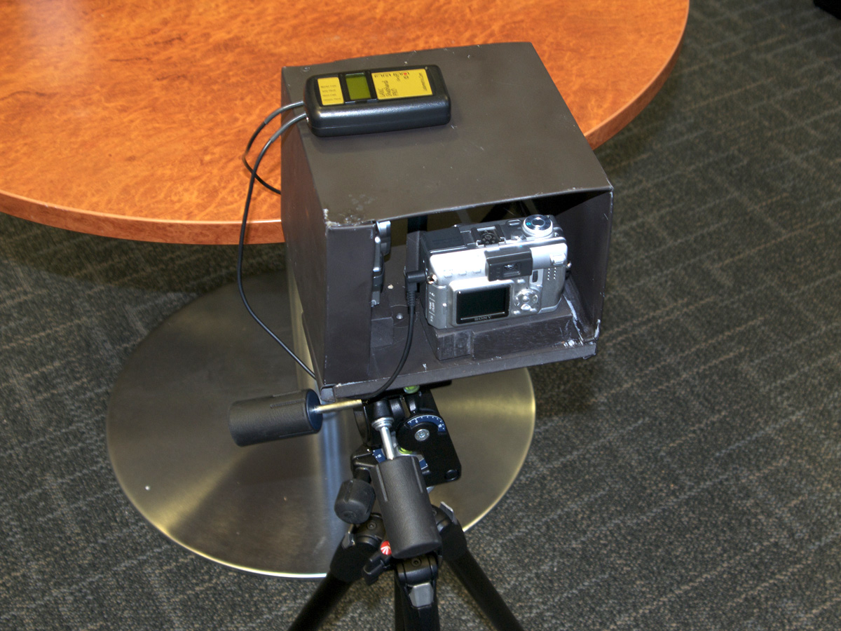
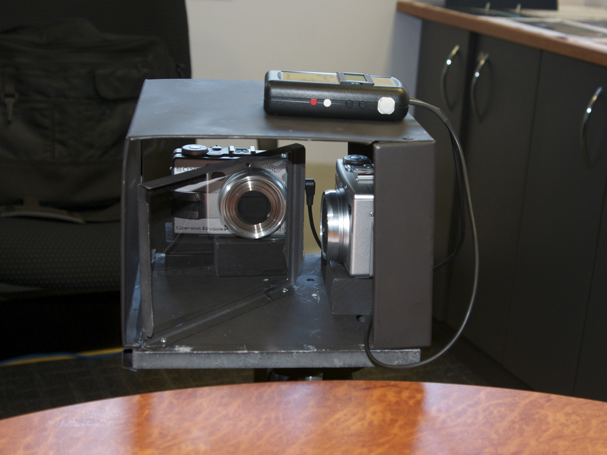
The following documents an approach to creating stereoscopic photographs and video of small scale objects, for example, live insects. The trick is achieving the small camera separation which is proportional to the size of the object being photographed. In order to take stereoscopic photographs of an object on the scale of a cm, one needs a camera separation on the order of 1/2mm, or less. While this can be achieved for stationary objects with a single camera offset at two different times, this approach is not acceptable for moving objects. 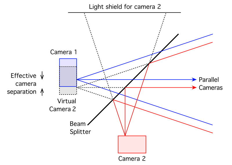
The solution here is to use a beam splitter to essentially fold the light path for one camera. The cameras are now at right angles to each other and the view frustums can be moved arbitrarily close to each other. A technique is also required to capture the images at the same time, in this case the LANC interface supported by older Sony cameras is used. A stereo LANC controller provides synchronised images within 3 or 4 ms. Unfortunately as of 2009 Sony seems to have discontinued this support in their current range of digital cameras, the solution would seem to reside with Canon cameras and the CHDK (Canon-hack development kit).
The images above show the very basic prototype: two cameras, beam splitter at 45 degrees, lanc controller, cover to ensure the second camera only receives light reflected from the beam splitter. Notes
Stereo Pair Photography (the low cost way)Written by Paul BourkeJuly 1999 Introduction Stereo photography involves taking a photograph from two positions, these correspond to two "eye" positions. The two cameras cannot just be arbitrarily separated and point in roughly the right direction. The separation depends on the distance of the closest objects in the scene and the degree of stereo one wishes to achieve. The cameras should be angled inwards * so that imaginary rays projected into the scene intersect at a depth that is intended to be at the projection plane. Objects that are closer than this intersection point will appear to be closer to the viewer, points behind this intersection point will appear to be further from the viewer. There is a limit to how close objects can be made to appear and still provide comfortable viewing, a general rule of thumb is for the camera separation to be around 1/20'th of the distance where the camera rays intersect.
The two photographs are presented independently to each eye by any number of techniques. Some people are able to focus their eyes on a more distant position and view the two images (stereo pairs) unassisted. Most people prefer some assistance in the form of a stereoscope or more recently by stereo computer graphics devices. Whatever the means, the result is the appearance of depth....the image appears to be 3 dimensional. The technique was very popular in the late 1800's and early 1900's where it was embraced by the relatively new photographic technology. The following stereo pair was taken of the USS Oregon with a specially design stereo camera in 1898. These images were originally designed to be viewed with stereoscopes which were developed in the early 1800's. The popular Wheatstone and Brewster stereoscopes used prisms and mirrors to present the left and right images independently to each eye.
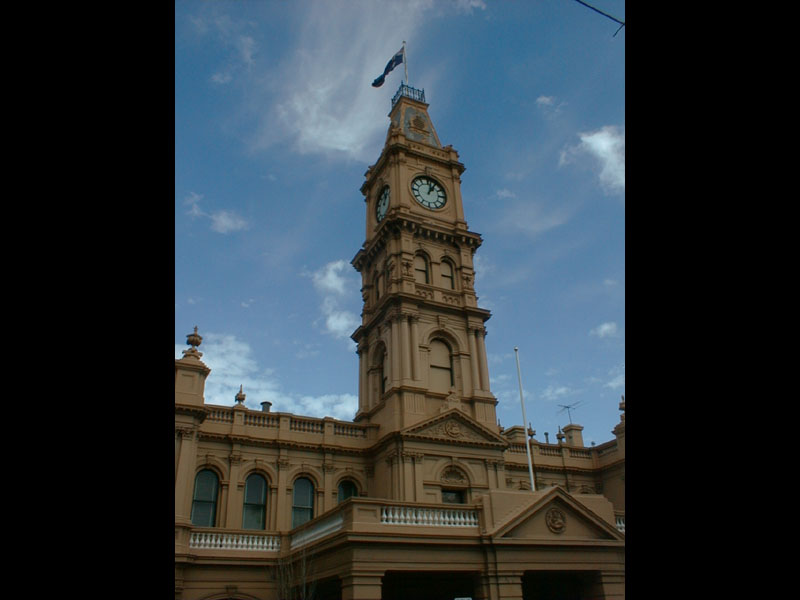
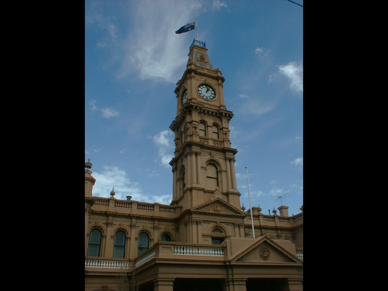
The following example was captured using a high definition digital camera. The clock tower is part of the town hall on the corner of Glenferrie and Burwood roads in Melbourne, Australia. One of the problems of using a single camera and taking two shots is that any movement in the time between the shots results in viewing degradation. For example in the following images, the area around the flag seems confused because it had moved between the two images. The two camera approach needs to be abandoned for the stereo photograph of all but still scenes, even moving clouds can ruin the effect.
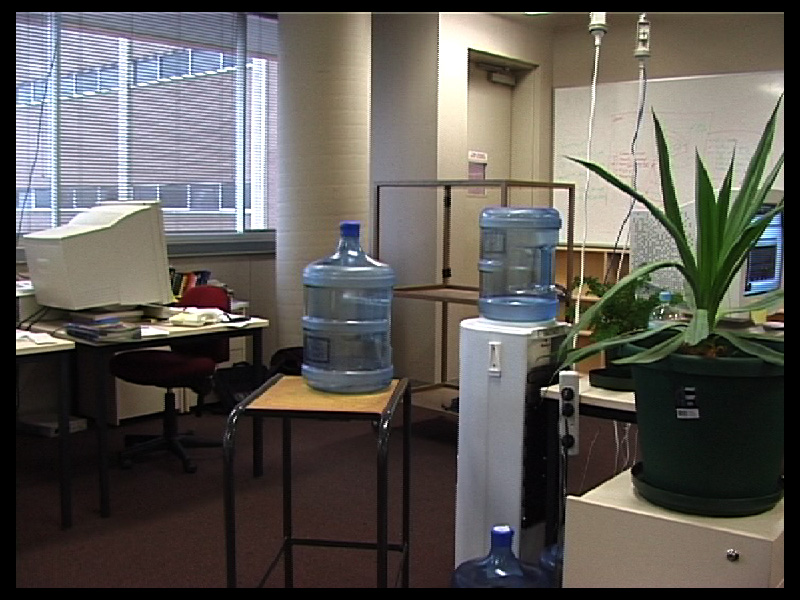
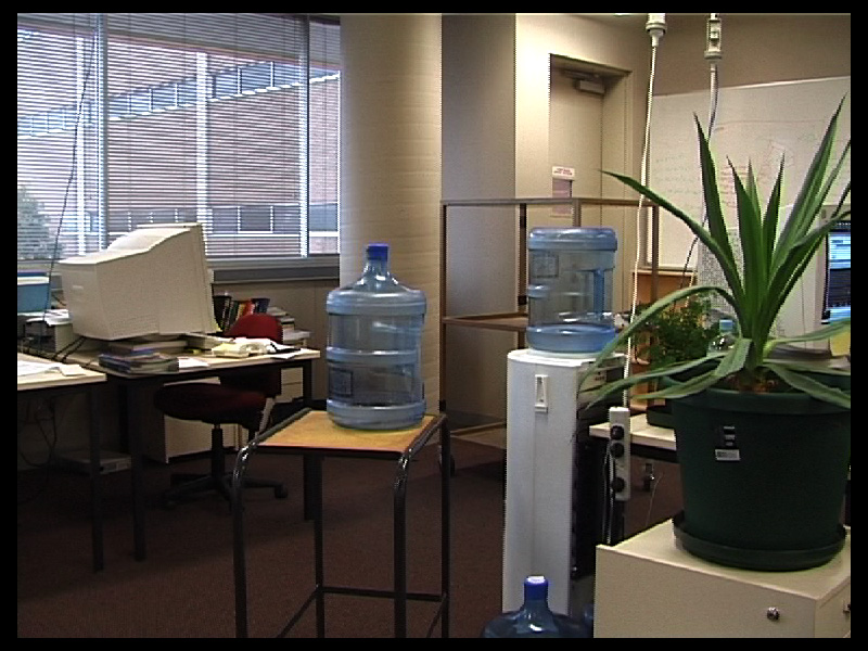
The question of the separation of the camera is not as straightforward as one might imagine. It depends on the size of the image in relation to you distance from it, as well as the degree of the 3D effect one might try to replicate. In practice it is good form to take a number of shots at various separations and combine the best pair by experimentation afterwards. Example 2The following image is one taken from a movie recorded using two digital movie cameras. This is much harder than taking single shots, both in terms of filming and the subsequent processing. The main ingredient is a strong tripod and mounting bar for the cameras. The mounting needs to allow the cameras to slide apart from normal eye separation to perhaps 1 meter separation. It needs to be able to be precisely levelled. The hardest part is turning the cameras so they focus at the depth of interest, normally the cameras are mounted on dials with a fine gear arrangement that turns the cameras together (but in opposite angle directions, one turns clockwise while the other turns anticlockwise). As with a single camera it is necessary to have a cross hair arrangement in order to point the cameras at the same point.
Given that the cameras are aligned properly during recording, if the cameras are not synchronised as is the case with two independent cameras, then the two captured video streams need to be aligned in time. For the exercise discussed here this alignment was done in the stereo viewing software itself but it could just as easily be done using one of the many commercial digital video editing packages available. It is assumed that the clocks in the two cameras are precise enough not to slip in time. The alternative is to use time locked (gen-locked) digital cameras, this is a much more expensive option than using independent "consumer grade" cameras. ViewingThere are many ways of viewing stereo pairs. A popular method in the early days of computer graphics was to use red/blue glasses and superimpose the two views into one image after turning the left and right views into the appropriate colour. So for example if the glasses had blue lens on the left and red lens on the right, then the left eye image would be shaded blue and the right eye image shaded red. This images resulting from this general technique are normally called anaglyphs. The example below is from the Mars lander which took a large number of stereo pairs from the surface of Mars.
The obvious problem with this method is that only grey scale images can be viewed. Another approach is to project the image with say two different polarisations of light and then the user wears glasses with the appropriate filters. Horizontal and vertically polarised light is frequently used but it doesn't allow head rotation. A better technique is to project with right and left circular polarised light. The projection simply involves two slide or movie projectors with filters over their lens, it is important though to project onto a screen that doesn't destroy the polarisation, metal projection screen satisfy this. More sophisticated techniques involve high refresh monitors that alternatively draw the left and right eye images. The viewer then wears glasses of some kind that allow the eye to see the images it is supposed to see. One approach is to use LCD shutters that alternatively turn from transparent to opaque, the shutter for each eye is synchronised to the images being displayed on the monitor. This synchronisation was first done by a cable but is now usually accomplished with an infra-red emitter allowing greater movement and comfort by the wearer. With the advent of reasonably low cost shutter glasses this technique is becoming popular in games for the home computer market. To be really successful and to minimise artefacts it is necessary to acquire a monitor with fast phosphor and LCD shutter with a fast response. Without these there can be significant ghosting, some of the left eye's image for example is seen by the right eye. An example of a viewing arrangement is shown below, the red light on top of the monitor is an infra-red emitter that synchronises the glasses with the alternating images on the monitor. 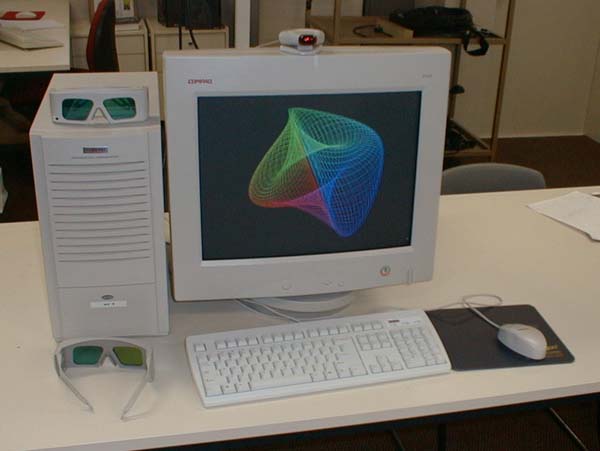 Source C source (glimage.c, glimage.h) or (glslides.c, glslides.h) for displaying stereo image using OpenGL and the glut library. This code is definitely not general but was written to form a "proof of concept". It displays two "raw" images in the left and right frame buffers, the image must be 800 by 600 and the monitor is assumed to be working in stereo at the same resolution. Other configurations should easily be able to be supported making small changes to this code. Toe-in and off-axis stereoThe method of turning in the two cameras is known as "toe-in". It isn't the ideal method to use since it introduces various distortions, most noticeably vertical parallax increasing out from the center of the image. It was discussed here because it doesn't require modifications to a standard camera or video camera. 
The better way to photograph stereo pairs is with what is known as off-axis projections, unfortunately this requires either special lens/film arrangements or in the case of CCD cameras the CCD needs to be shifted horizontally on both cameras (in different directions). When using an off-axis camera the cameras are mounted parallel. 
Another option is to photograph a slightly larger view than is intended with parallel cameras. The off-axis projections are created by aligning the two images and clipping off the unused bits, this will involve removing a strip on the left of the left pair and a strip on the right of the right hand pair. The exact amount to cut off can be determined by eye by visually inspecting the alignment or calculated by straightforward geometric considerations. Photoshop is particularly good for visually aligning the pairs because they can be superimposed with one slightly transparent, no doubt other image manipulation packages can achieve the same result. References
Ferwerda, J.G.
Lipton, L.
Marshall, G. and Gandland, G.
Okoshi, T.
Waack, F.G.
Manual Creation of Stereo PairsWritten by Paul BourkeApril 2001
While most stereo pairs are created with either stereo cameras or by computer, it is also possible to manually edit a normal photograph and introduce stereoscopic 3D effects. The basic requirement is the ability to selectively (generally using computer based image editing software) choose objects that should appear in the foreground or background. These objects are displaced horizontally on each stereo pair image, the amount and direction of the displacement dictates the depth and whether it is in front of the image plane or behind the image plane. The technique used here will be discussed with an example, the original image is shown on the top-right hand side. The idea isn't difficult but can be tedious and for more complicated images can require a sound methodology and careful planning. The first processing in this example was to remove the noisy appearance between the galaxies and stars. The plan is to keep the two galaxies in the plane of the image (0 parallax), the white stars will be brought towards the viewer (negative parallax) and the smaller reddish stars and galaxies will be moved into the distance (positive parallax). If the noise in the plane of the galaxies isn't removed it will form a strong appearance of a plane. The different objects are marked (on a separate painting layer) with different colours depending on their intended depth. This method was chosen simply because it is easy to then select the regions by colour using the tools in the particular image editing software being used (PhotoShop). The red objects will be brought closest to the viewer, green further away but still in front of the image plane, blue and yellow are progressively further away. The more depth variation used the better the end result but it greatly increases the time consuming nature of the process. At this stage two images are created, one for each eye. The appropriate pieces are copied/pasted onto different layers within these two images. The layers are then shifted left and right as appropriate. For example the red objects are shifted to the right in the left eye image and to the left in the right eye image (negative parallax). The yellow objects are shifted left in the left image and right in the right image. 
The amount of separation requires some experience. Objects that are to be at infinity are separated by the intended eye separation, objects brought towards the user shouldn't be separated by more than this eye separation. The amount of separation is also dependent on the way the stereo pairs are presented to the viewer, some systems can sustain more separation than others. It is possible to leave one eye image as it is and just shift the layers in the other image by twice the amount, the only issue with this is it increases the chance of problems at the left and right edge where there isn't enough information or where an object on one stereo pair disappears off the the side during the shift. 
|