Synthetic dynamic hologramsWritten by Paul BourkeApril 2007
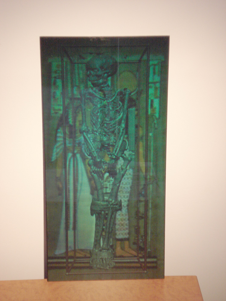
Initially inspired and assisted by Jacques Desbiens The following describes an initial evaluation of synthetic dynamic holograms, that is, holograms that reconstruct 3D virtual objects and change (smoothly) as the observer moves. Additionally the holograms are full colour when illuminated with white light and can be created at large scales. Holograms have the advantage over other computer based stereoscopic techniques in that no glasses are involved, for this and other reasons there is no eye strain. They have the advantage over lenticular and other autostereoscopic projection systems in that they can be much higher resolution. In addition the above traditional approaches to stereoscopy have by comparison a very small number of points of view that limit the viewing flexibility. Of course the disadvantage is that they can not be generated in realtime (yet and into the foreseable future). However this is slightly mitigated by the dynamic nature of the holograms (holographic panoramagrams) presented here, that is, they can encode a (short) animation sequence that is revealed by the observer moving to a different locations. This "animation" can be both discrete or occur smoothly. RenderingThe example used here for the evaluation is a visualisation/rendering of a CAT scan of an Egyptian mummy. [Further examples of rendering this model can be found here]. There are two aspects of the scene that are animated, the camera is translated from the left to right along a straight track. The rendering at each camera position is a raytracing of an isosurface, the isosurface is slowly varied as the virtual camera is translated left to right. Note of course that the same process could be performed for capturing and encoding these holograms using a camera on a horizontal sliding rig. 
A total of 1400 frames were created, an example of frame 300 is given below. Irrespective of the technology of producing the hologram, one can appreciate that this process contains all the visual information necessary to reconstruct the 3D views of the object/scene. 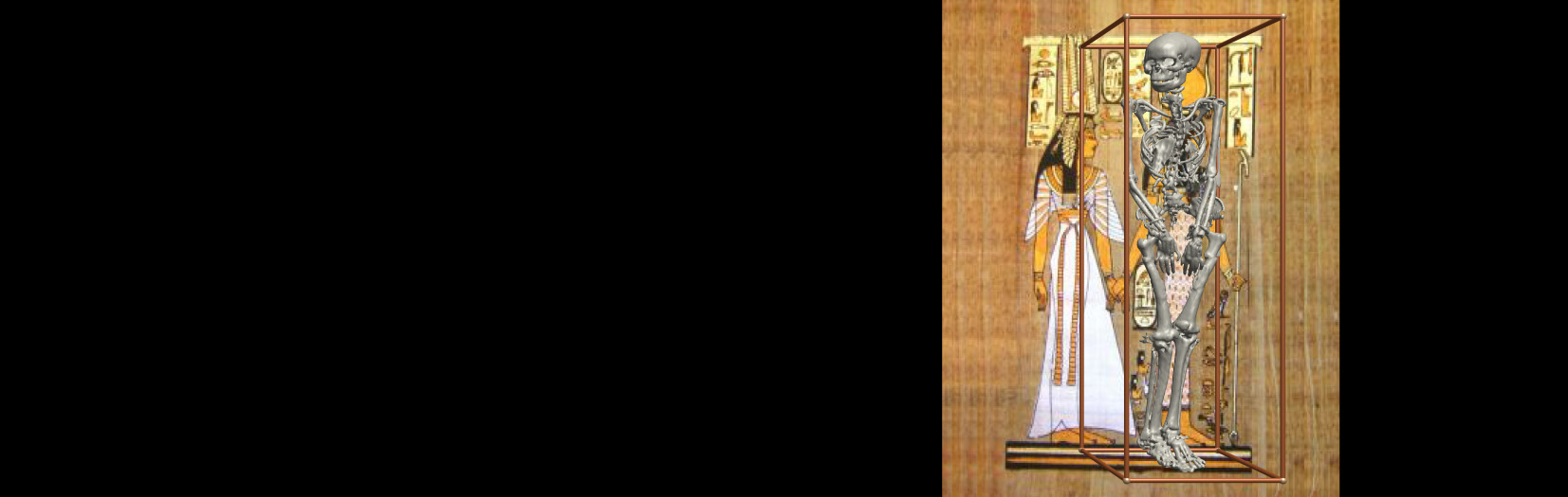
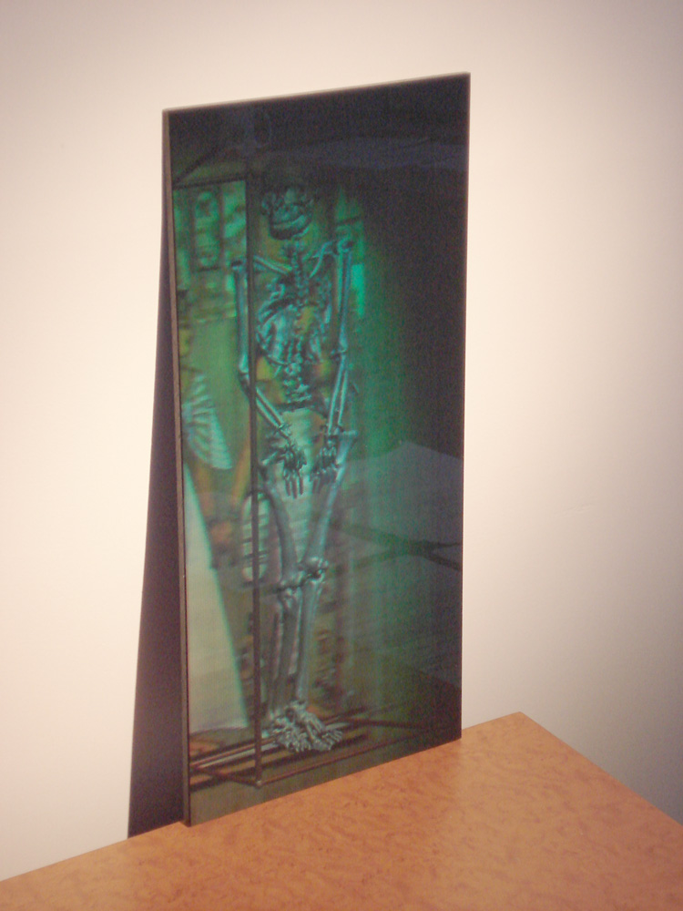
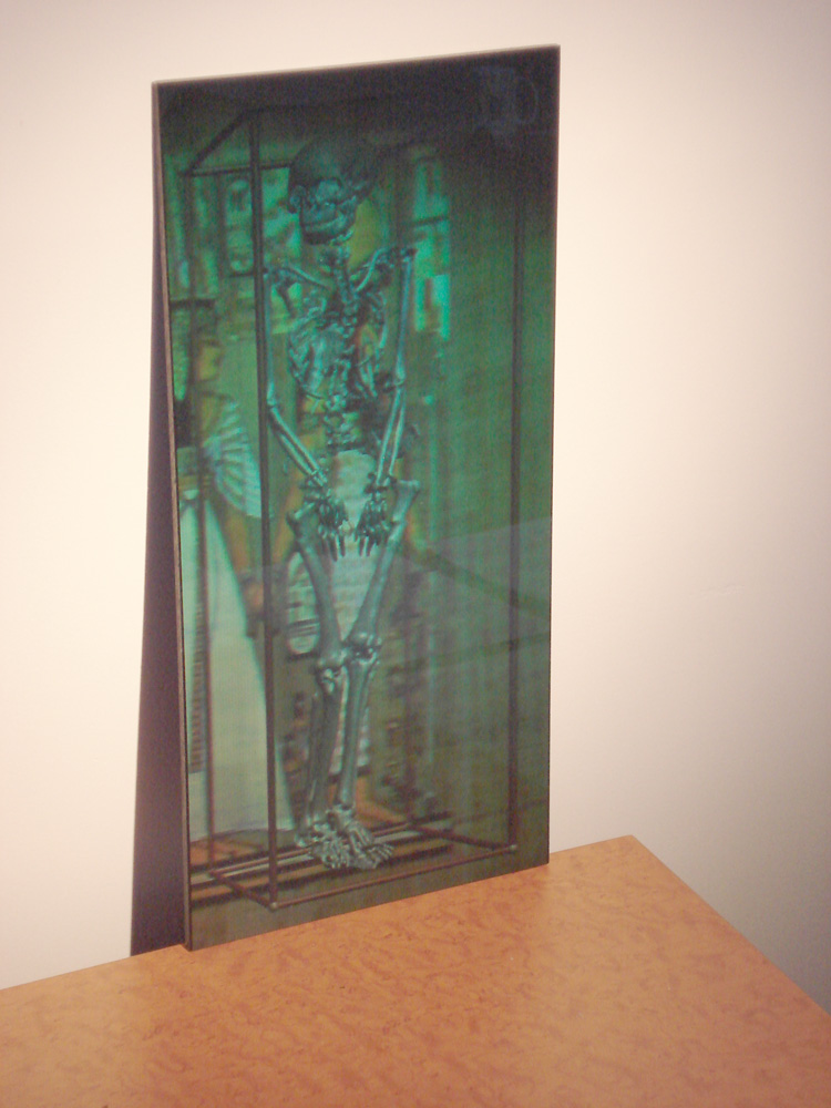
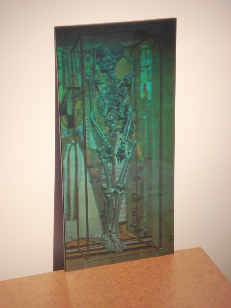
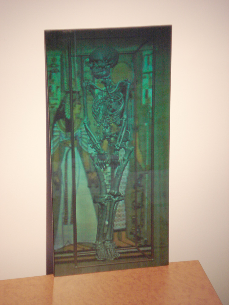
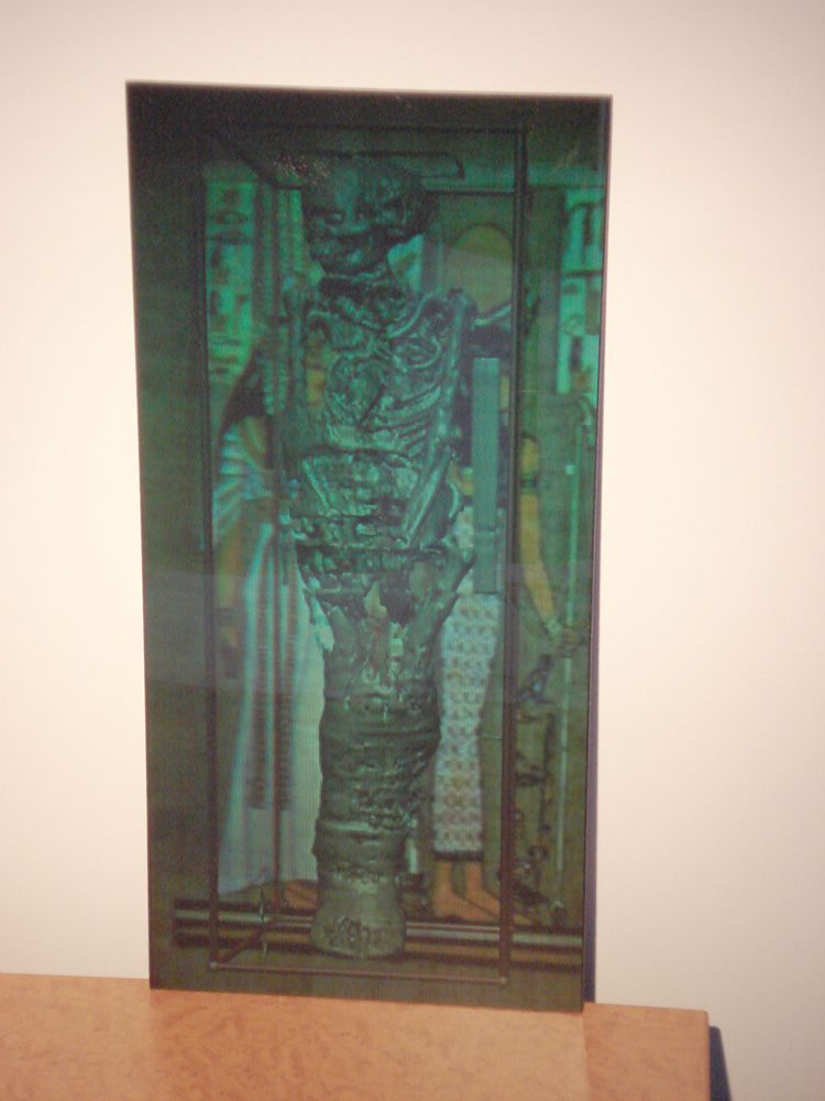
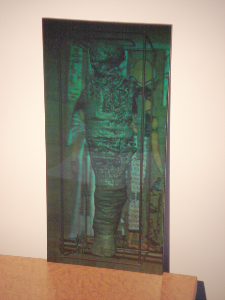
Samples While the following sequence of photographs taken at different positions moving left to right along the real hologram do not do justice to the 3D view ones sees in real life (with two eyes), they do illustrate the varying parallax and the nature continuous animation. The final size of this hologram is 420x200mm with 0.8mm holopixels.
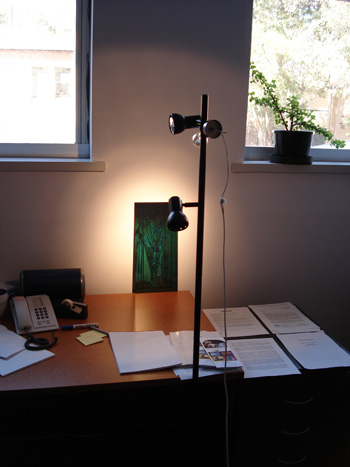
Viewing/lighting
Geometry
Geola provide a calculator that given a hologram size gives the camera specification, such as distance from the hologram plane, field of view, length of the camera track, etc. As with all stereoscopic systems there are limits to the degree of acceptable separation and in particular negative parallax. Geola recommend approximately 25% of the hologram depth should be in front of the hologram plane. Unlike other stereoscopic systems there are also limits on the recommended maximum depth. The following diagram gives an indication of the relevant parameters. 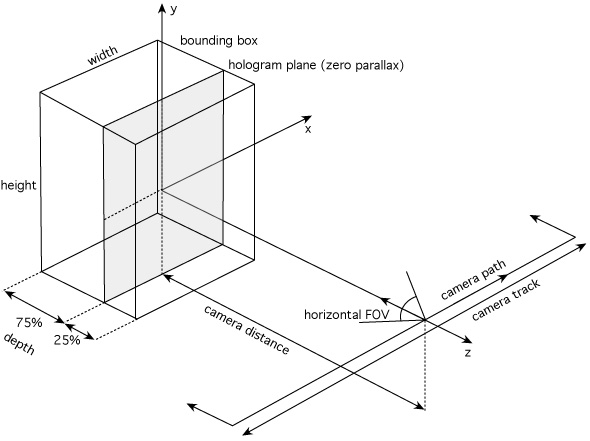
Note that many graphics APIs use the vertical field of view for the camera, this can be computed from the horizontal field of view as described here. Example 2: Placoderm fish "teeth", CT scan
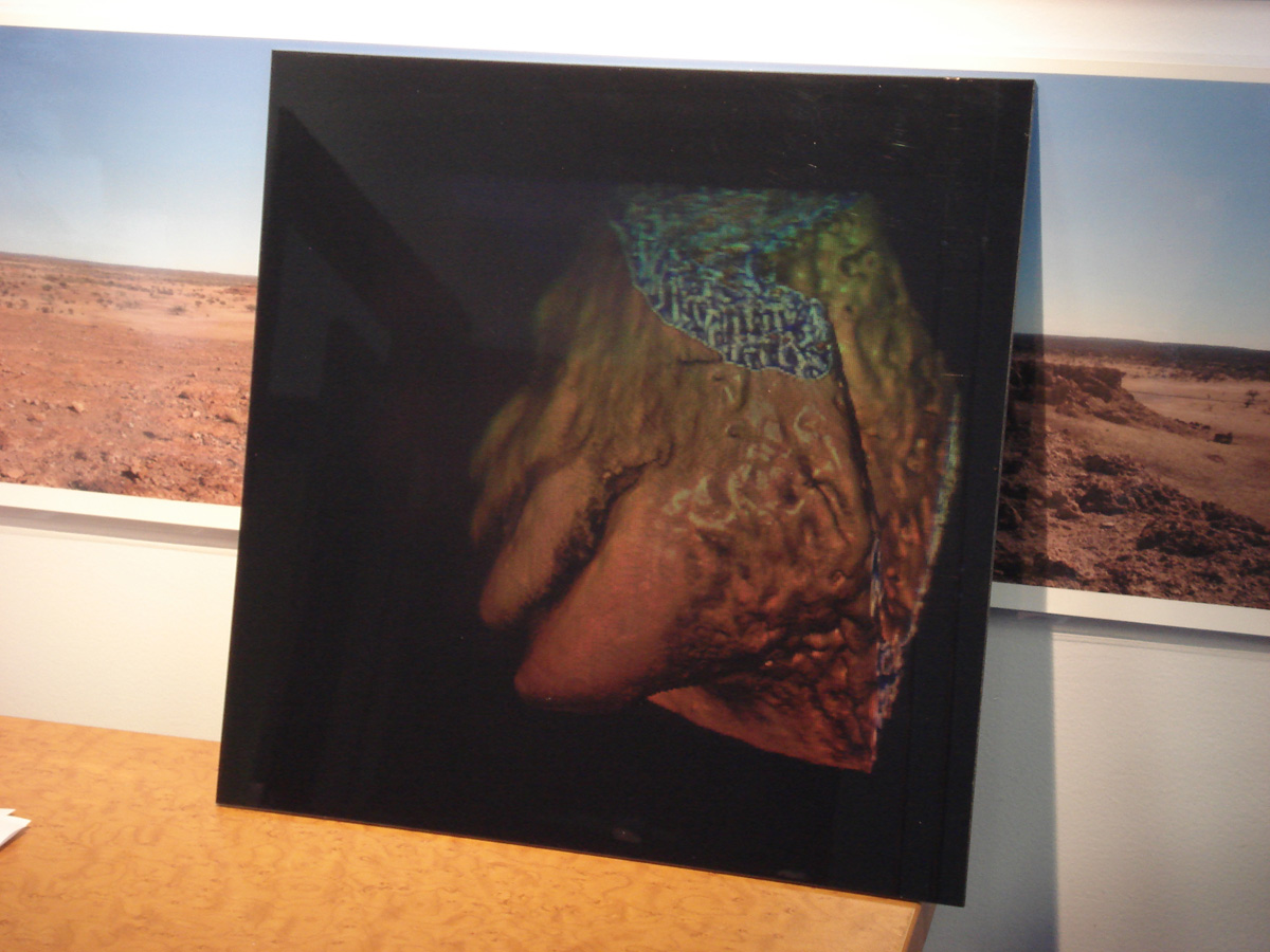
The next two examples relate to the use of this technology for scientific visualisation, in particular, for presentation to peers at conferences (where other stereoscopic presentation options are not portable) and for engaging presentation of science for public outreach. The first example is the teeth from a fossil of a 400 million year old Placoderm fish. The fossil is scanned using a CT scanner, the resulting volumetric data is rendered using the Drishti software.
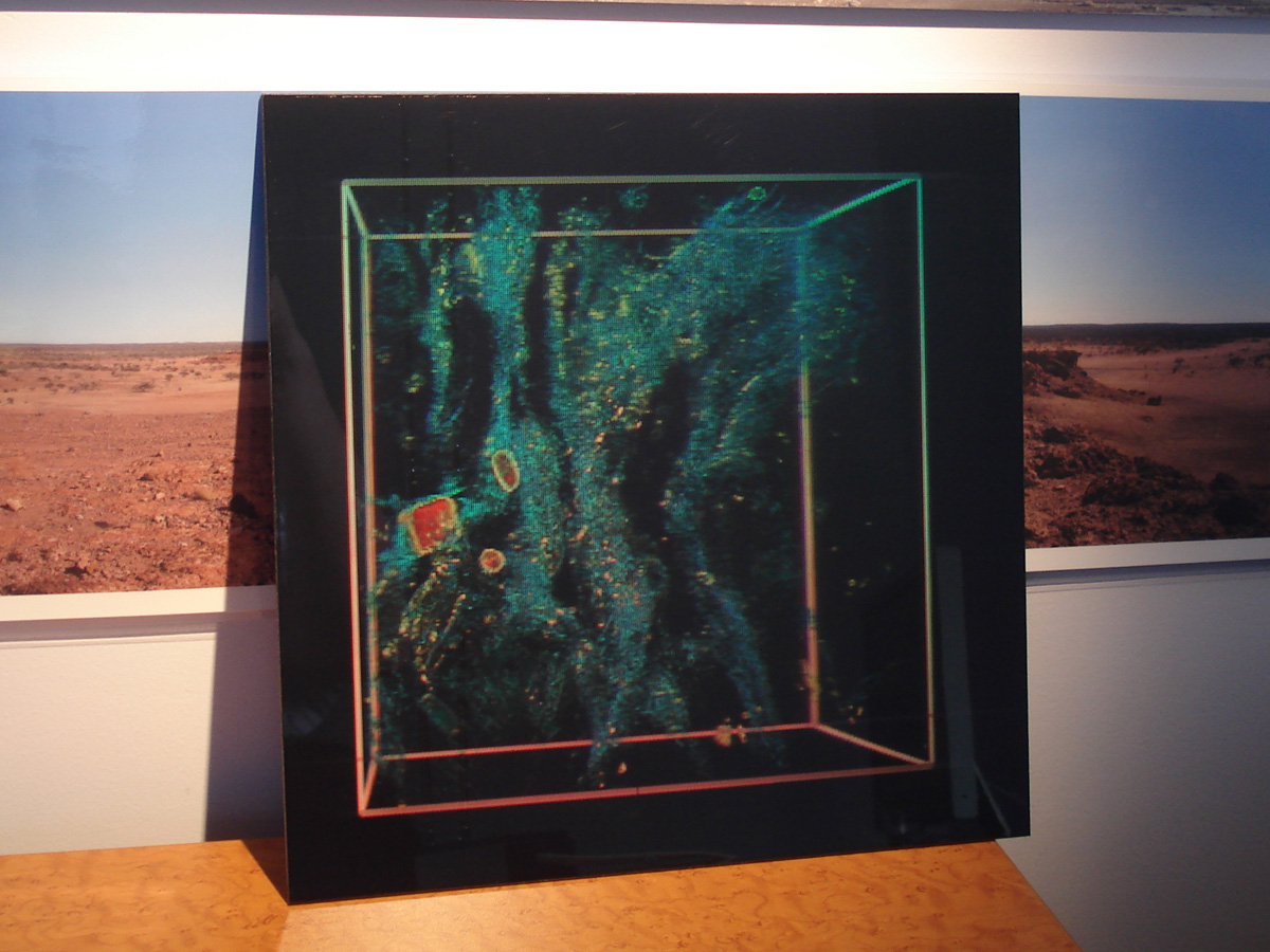
Example 3: Rock sample, CT scan
In this example by geologists, a small rock sample has been CT scanned and volume rendering (also Drishti) can revealed the internal structural elements. While the photographs here do not do justice to the 3D look one acquires in real life, they do illustrate the different parallax from different viewing positions.
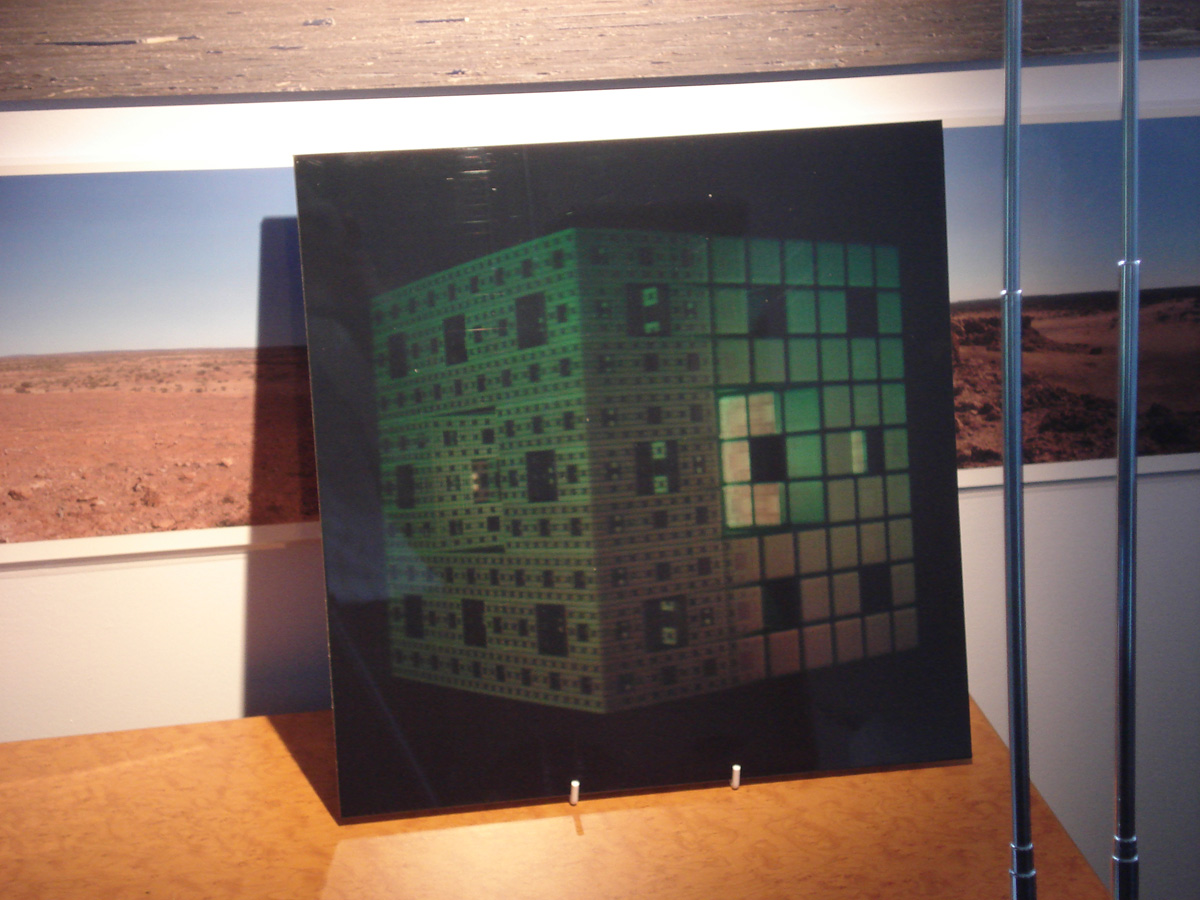
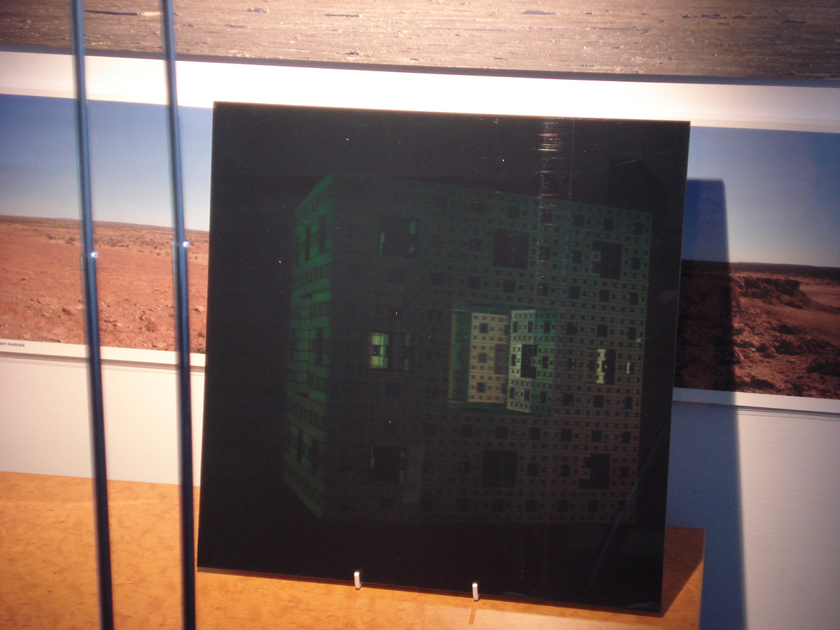
Example 4: Menger Sponge
An example of three discrete phases rather than a smooth animation. In this case the sponge is rendered at three different stages, the highest resolution is observed when viewing it from the front, two different lower resolutions are observed when viewing from either side ... thus illustrating how the Menger sponge is created.
Example 5: Cliff face
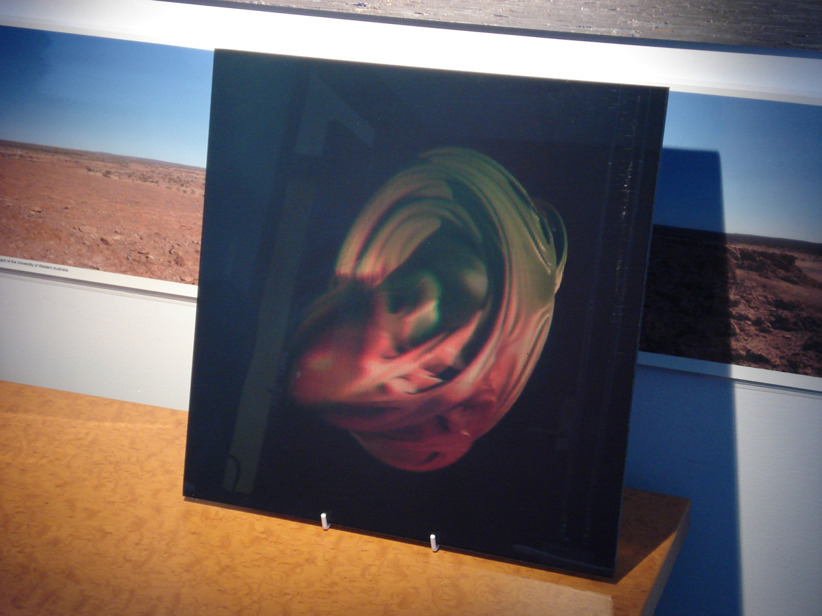
Example 6: Quaternion
This is a quaternion fractal, a 4 dimensional object slices of which yield a 3 dimensional object that we can render. In this case as one moves horizontally one is varying the cutting plane and therefore essentially (kind of) moving in the 4th dimension.
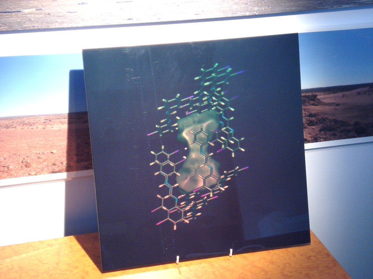
Example 7: Molecule
|