Create side-by-side stereo pairs in the Unity game enginePaul BourkeDecember 2008 Sample Island project: Island_stereo.zip See also: Using Unity in the iDome
In the following I will outline one way of creating stereo pairs within the Unity game engine. Since Unity does not support quad buffer stereo (also known as frame sequential stereo) the approach here is suited to dual projector stereoscopic projection, most commonly this would be a polaroid or Infitec based stereoscopic systems. The technique outlined below involves parallel cameras (as opposed to toe-in) and as such creates optimal stereo pairs without vertical parallax. The reader is assumed to be moderately familiar with Unity3D, screen shots are provided along with each step discussed. The reader is also assumed to be familiar with the basic theory required to generate "easy on the eye" stereoscopic pairs, this includes the relationship between eye separation and the distance to zero parallax. The method here requires render to texture and as such Unity-Pro is required. The example adds stereoscopic support to the demo environment that ships with Unity. The first step is to create two cameras, one for each eye. In the following, one of the cameras of the standard first person controller is duplicated. Each camera is offset horizontally about the central position of the original camera (in this case by +-0.03 units). Two render textures are created and the cameras set to render to each one. The stereo projection system is XGA (1024x768) so 1K render textures are adequate. An open question is what eye/camera separation to use. For strictly correct stereoscopic projection a knowledge of the viewing screen is required, for this more casual setup one commonly used strategy is to choose a zero parallax distance that is equal to the distance of the camera to the ground. The eye separation then is typically (a common standard) 1/30 of this zero parallax distance. In order to give the most realistic sense of depth the field of view of the two game controller cameras should be close to the field of view of the players eyes to the bounds of the real stereoscopic display. 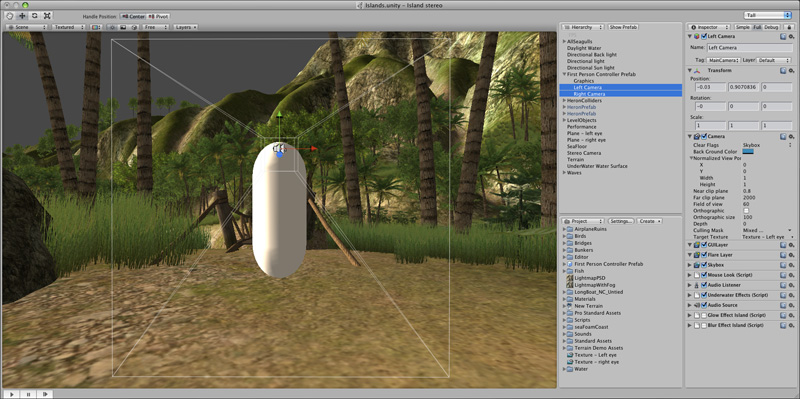
The two render textures are applied to side by side square planes. These are both placed on a separate layer so they can be precluded from the first person controller cameras, and can have independent lighting applied. While not strictly necessary, a parallel light is also applied to the "stereo" layer, this provides additional control over brightness and even can apply colour (mood) effects. 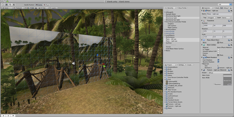
Finally an orthographic camera is positioned centered on the two render texture planes. It is set to cull all layers except the stereo layer. The zero parallax is controlled by trimming columns from the left of the left image and off the right of the right image, this is described here. This trimming is controlled by the "orthographic size". However, the relationship between the player window aspect ratio and the correct orthographic size (for a particular zero parallax distance) is somewhat convoluted due to some "magic" in the choices made by Unity. The solution is simply to place an object like a small sphere temporarily in front of the camera rig at the desired zero parallax distance and adjust the orthographic size until it is indeed appears to be at zero parallax. Note that the game window below is not filled with the stereo pairs, this is because it doesn't have the right aspect ratio of 8:3 (2048x768). 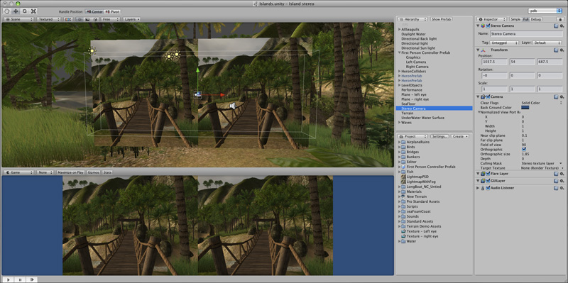
The following shows the left and right image side by side. The left hand image is sent to the left eye projector and the right hand image sent to the right eye projector. In this case the splitting effect is accomplished by using the Matrox dualhead2go cards to give the desired 2048x768 pixel buffer. 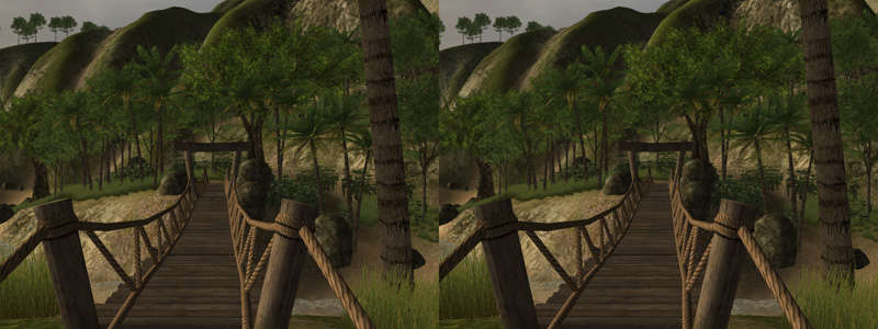
The two images overlaid with 50% transparency shows how the parallax increases with distance and the front posts are at the intended zero parallax distance, and there is no vertical parallax. 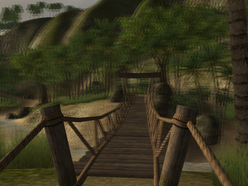
In order to avoid excessive negative parallax for objects that approach the cameras one may choose to increase the front cutting plane of the two controller cameras to be some reasonable fraction of the zero parallax distance. This depends on the ghosting of the projection system, for polaroid systems this cutting plane may conservatively be set to 1/2 the zero parallax distance, this ensures that the maximum negative parallax equals the maximum positive parallax. For lower ghosting systems such as Infitec the cutting planes can be set closer to the camera. The authors stereoscopic viewing system, rear projection linear polaroid. 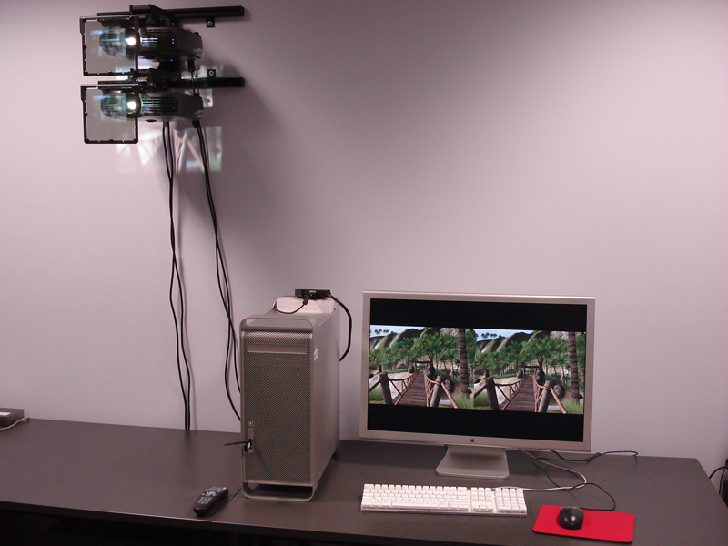
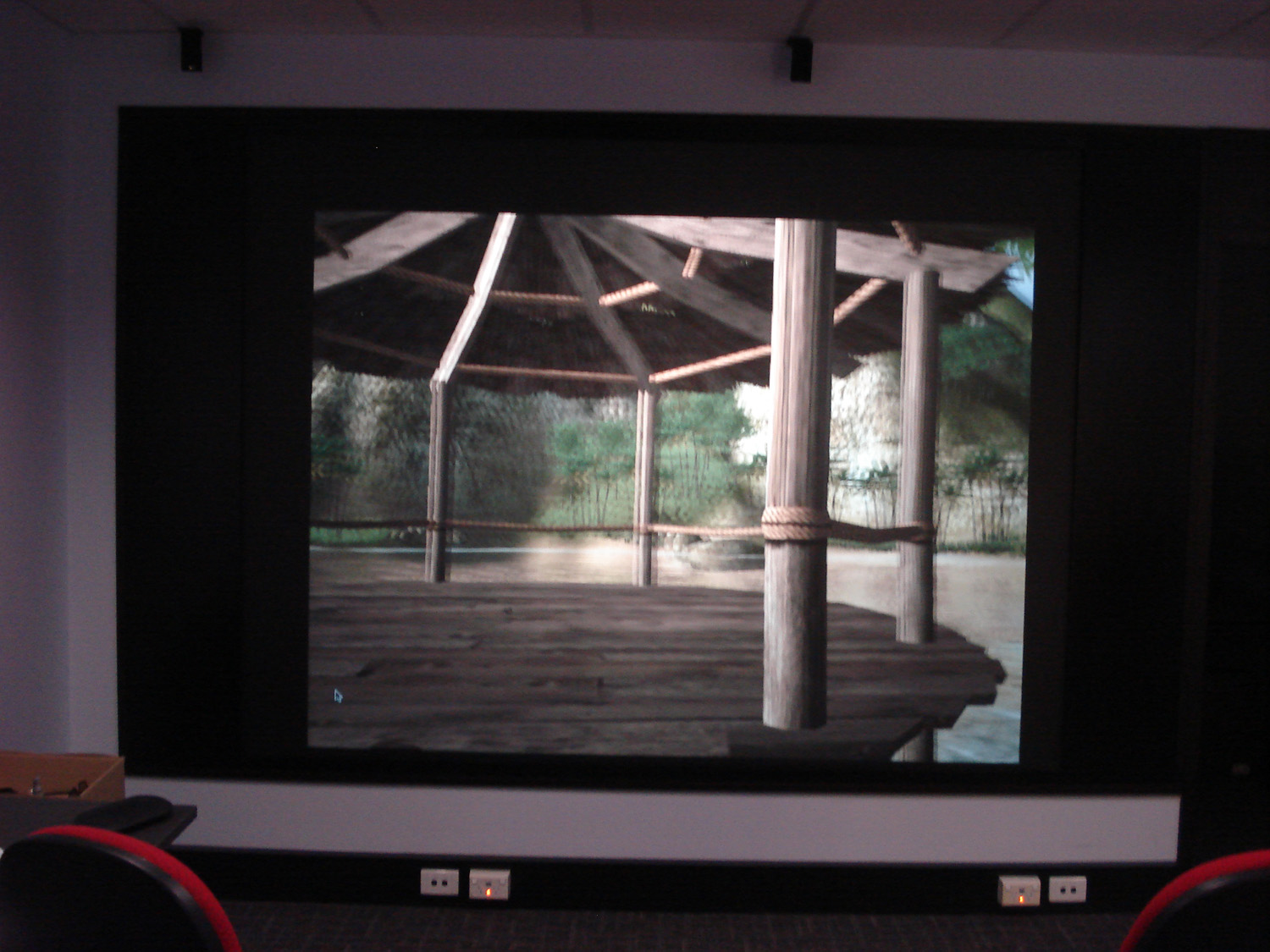
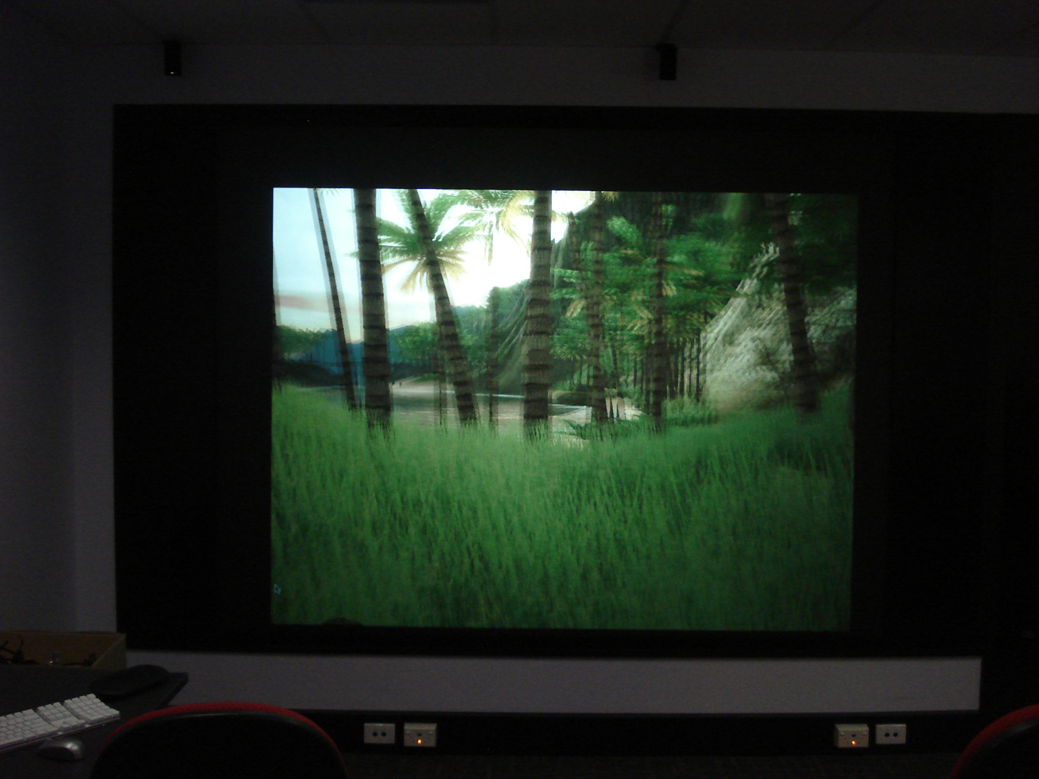
Photographs of the display.
|
