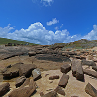
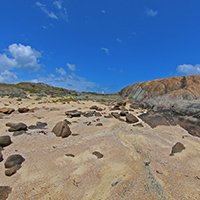
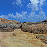
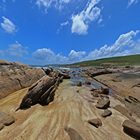
Workflow for creating 360 spherical (equirectangular) panoramasPaul BourkeDecember 2013
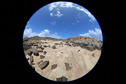
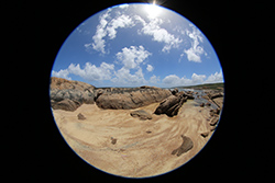
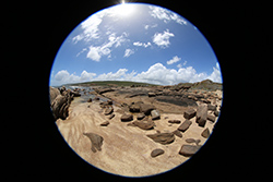
The following describes a work flow for processing 360x180 degree panoramic images captured with a SLR camera and 180 degree fisheye lens. While there are higher resolution options involving more camera shots and motorised rigs, the process described here is suited to cases where a large number of panoramas need to be captured in a short time frame. The hardware used here, only one of many options, is a Canon 5D MK III and Canon 8-15mm fisheye lens. This configuration can be used in two ways, three shots with the camera in landscape mode or for higher resolution 4 shots with the camera in portrait mode and the fisheye zoomed to fit vertically. The former uses the height of the camera sensor and the later the width, for the Canon 5D the former results in a spherical image approximately 8000 pixels across, the later in a 12000 pixel wide image. The three shot option will be used in this document.
Stitch with AutoPano Pro
A document such as this can age quickly as software versions change or new/better software comes on the market. The intent here is to document one solution, the reader can hopefully adopt this to changing circumstances in the future. As such, the optimal settings for AutoPano Pro will not be discussed, the reader should read the manual and explore whichever stitching software they choose. 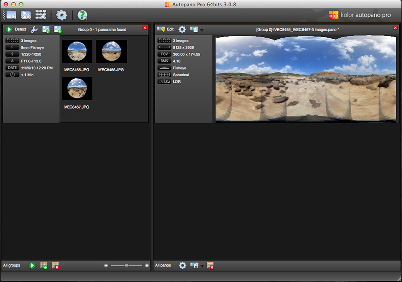
Check the lens focal length and fisheye has been detected properly. If using a lens that does not reflect the specifications in the EXIF data (such as the Sunex 5.6mm fisheye), enter the information manually. 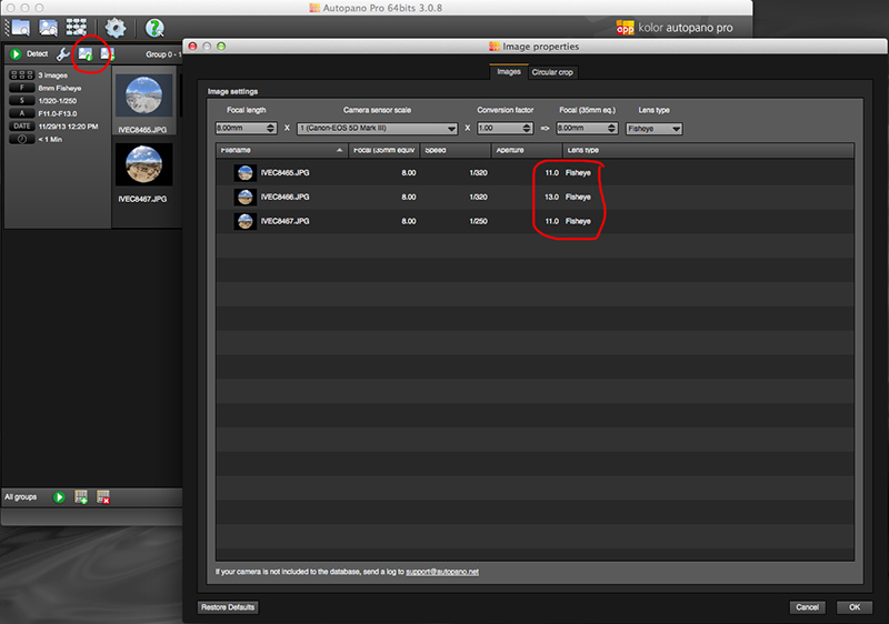
Check circular detection of the fisheye, it can sometimes get confused by lens flares and internal reflections from the lens ring. Adjust the circle using the yellow circle and generally apply to the other fisheye images. 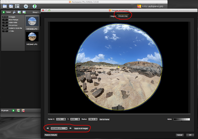 Generally render as 16 bit psd files, this will give maximum scope for image adjustment in the next step without quantisation errors. A typical stitched image as shown below will have artefacts at the top and bottom, it is these regions where lens non-linearity's have an effect. They will also occur where the lens is rotating about other than the nodal point. 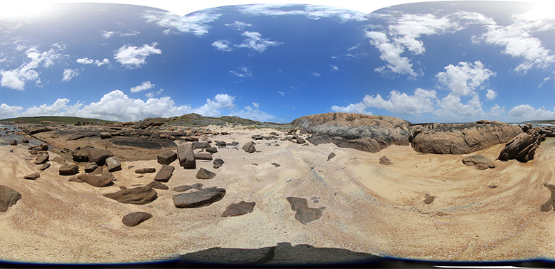 Editing
Common editing functions include shadow/highlight adjustment, vibrance, and possibly sharpening. While the author uses Adobe Photoshop there are other alternatives such as GIMP that for the most part has the same tools. The colour graded result is exported as 8 bit TGA, in this case called "pano.tga". 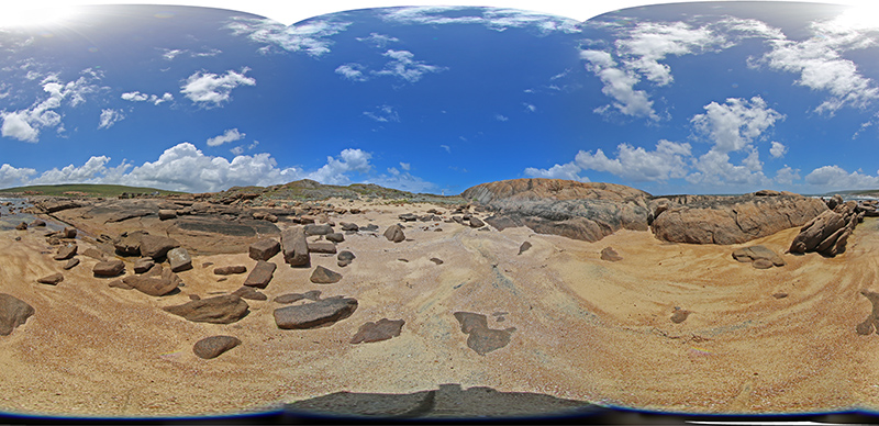 Create cube maps
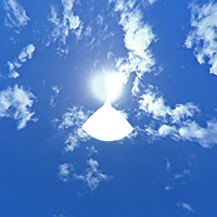
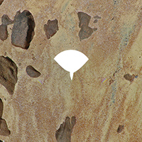
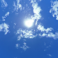
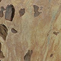
Editing the spherical panorama is next to impossible due to the most common regions needing editing being at the north and south poles of the image where there is maximum distortion. The solution developed by the author is to render out cube maps, 6 x 90 degree field of view standard perspective projections for editing followed by recombining them into a spherical projection (if necessary). The following command line (authors software) create cube maps that are each 2048 pixels square with a 3x3 supersampling. sphere2cube -w 2048 -a 3 pano.tga The result are 6 TGA files with names "l_pano.tga", "r_pano.tga", "t_pano.tga", "d_pano.tga", "f_pano.tga", and "b_pano.tga". The prefix is fairly obvious: left, right, top, down, front, back. As with the spherical panorama, the combined cube maps represent a complete recording of the scene. Note the holes in the centre of the top and bottom faces of the folded out cube.
Edit cube faces in PhotoShop
In general the top and bottom images need to be edited, note that in this case the camera was hand held and as such the edit zones are quite large. With a tripod and careful alignment of the nodal point of the camera/lens the edit regions will be significantly smaller. The only time the left, front, right, and back images need editing is if the photographers shadow strays into those zones.
Editing generally involves use of the rubber stamp tool, copying pixels from a similar nearby portion of the image to cover the hole or shadow. If there is a constant colour sky a large circular selection and Gaussian blur can hide pinching effects at the north pole. Otherwise it is left up to the reader to develop his/her skills. Care must be taken when editing across a cube face boundary since that edge needs to match with another cube face edge. Create spherical projection from cube maps
The reverse operation is applied to turning the cube maps back into a spherical (equirectangular) projection but now with no artefacts at the poles. The following creates a 8192 wide pixel image with 3x3 supersampling antialiasing, again using the authors command line software. The resulting file will be prefixed with "s", so "s_pano.tga". cube2sphere -w 8192 -a 3 %c_pano.tga 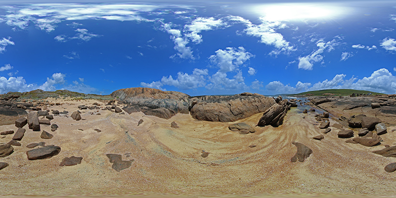 Addendum
It goes without saying that the camera should be set to automatic in order to get a consisted colour/exposure across the three images. This equally applies to things like white balance. If a variation does occur a strategy that works well is to use histogram matching between two of the photos and a third. The matched histogram is generally the most colour rich (master.png). The tool used by the author is the "bcmatch" script that uses the Image Magick" tools. If the two images to be histogram matched to the master are a.png and b.png then the command line conversion might be as follows. bcmatch -c rgb master.png a.png a2.png bcmatch -c rgb master.png b.png b2.png This obviously is the very first step being applied to the original fisheye images. In order for the large area of black around the fisheye not to bias the results the images should be circularly selected and the region outside the fisheye circle set to transparent. |
