Creating equirectangular projection for multipass rendering, eg: Unity3DWritten by Paul BourkeFebruary 2019
In the following: Creating fisheye views with the Unity3D engine a multipass rendering technique was introduced to create a fisheye projection. It involved rendering 4 faces of a cubemap and applying those to four specially designed meshes such that the result is a fisheye. The following illustrates the same technique but to create an equirectangular projection instead of fisheye. Obviously, unlike the fisheye case, one needs to render all the 6 faces of the cubemaps. The process is similar to cube2sphere described here: Converting to and from 6 cubic environment maps and a spherical projection except the approach here is suited to realtime applications. Creating the 2D mesh that will have the 6 cubemaps applied as textures involves creating a cube with each face tessellated into a regular grid. Here the grid resolution in the examples is 64x64 square cells per face. The (u,v) coordinates of each vertex of this mesh relate to the cubemap textures, so a simple linear samplings on each axis. The (x,y,z) coordinates of each vertex of the 6 meshes are mapped to longitude and latitude, the longitude ranging from -2π to 2π and the latitude ranging from -π to π, the expected 2:1 aspect ratio. This is now a 2D mesh, to be precise 6 meshes, one for each face of the cube. The untextured mesh is shown below, the cube nature is clearly evident. 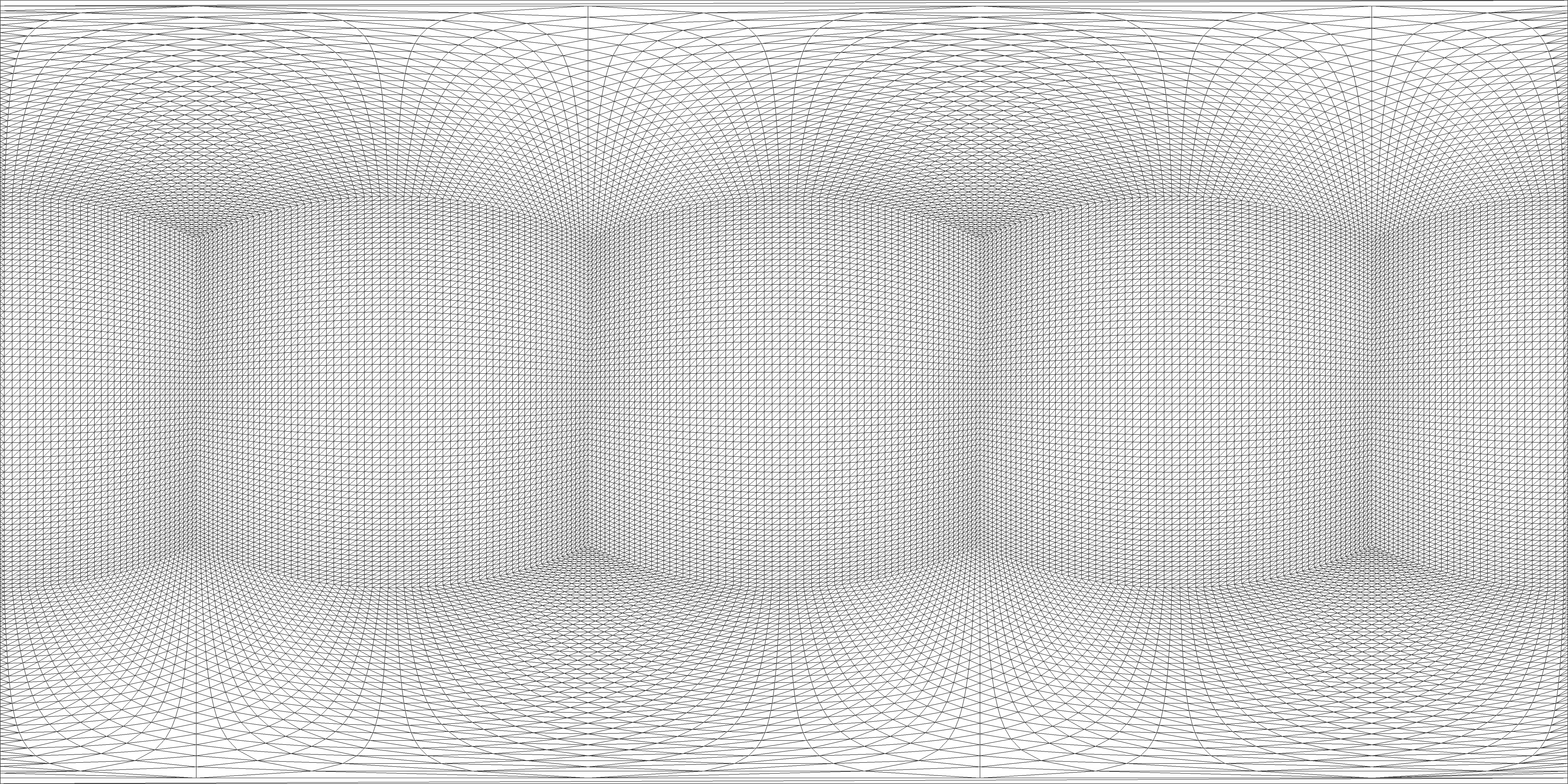
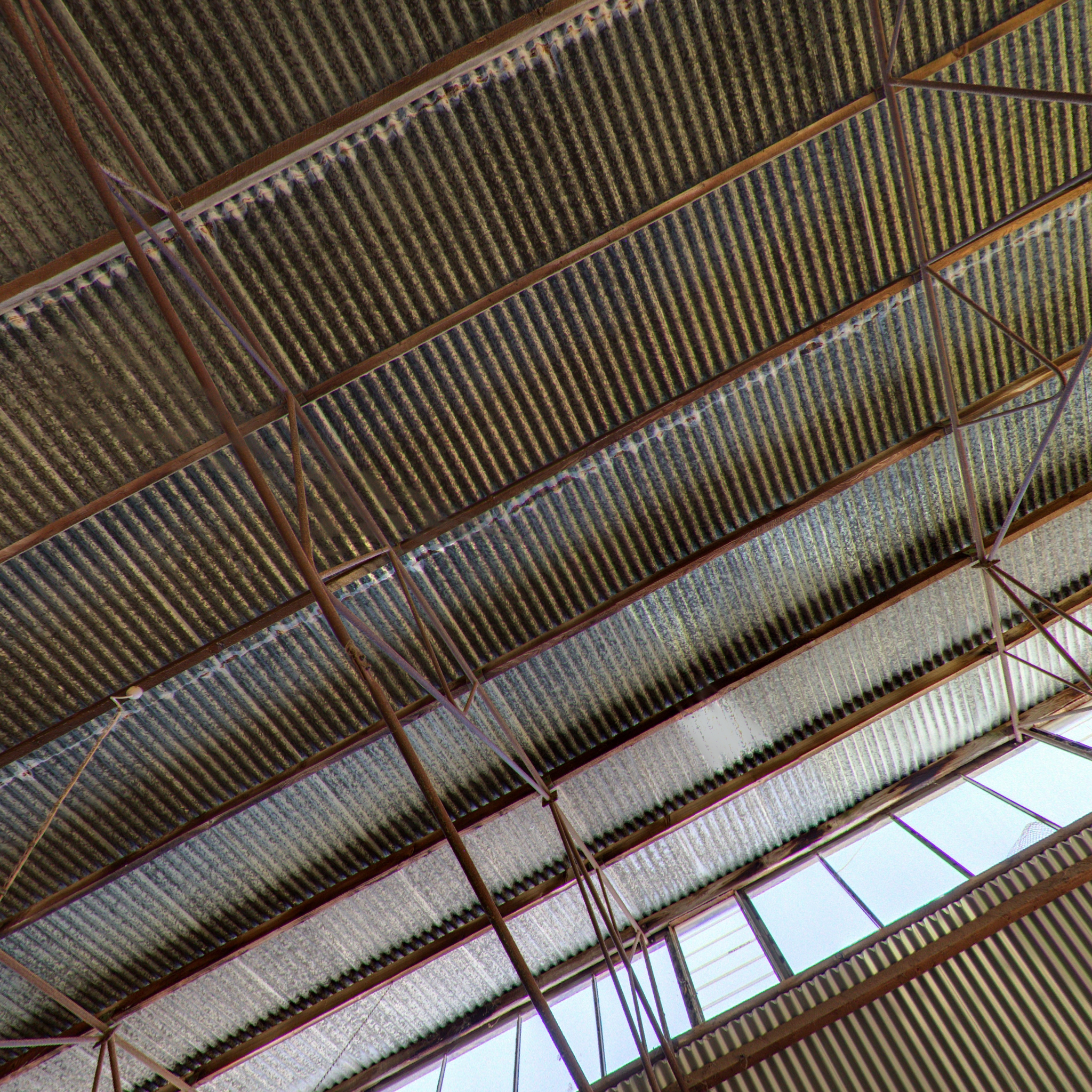
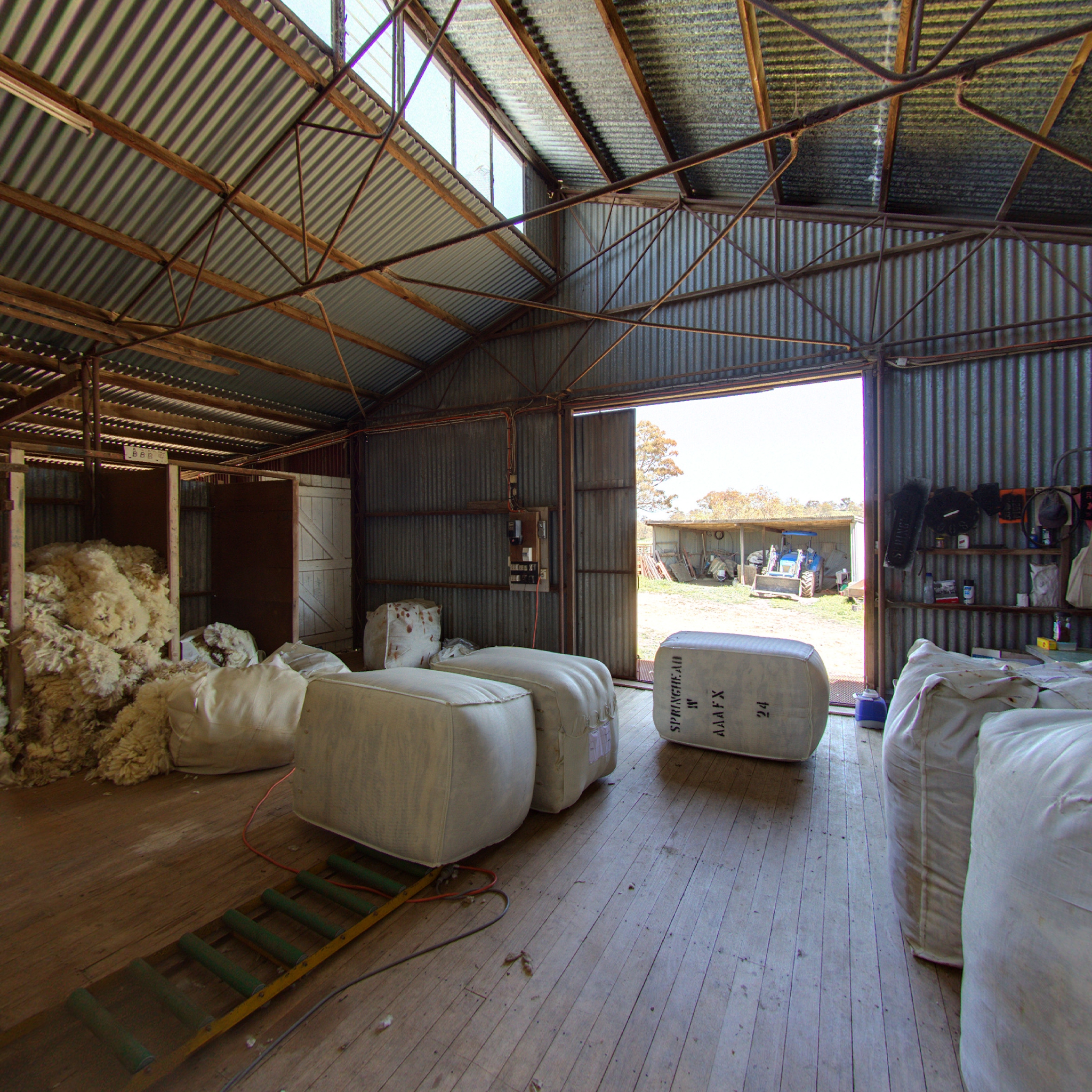
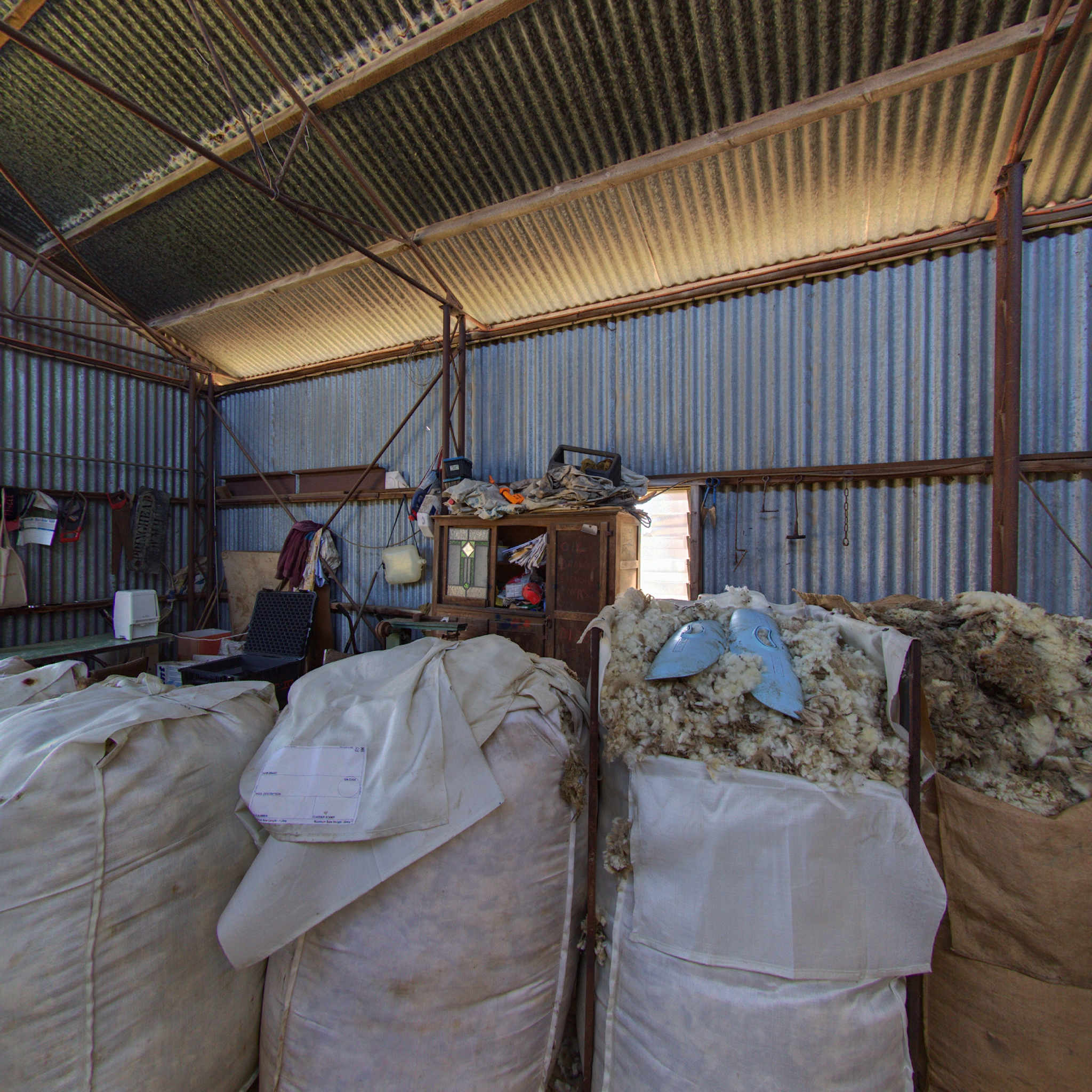
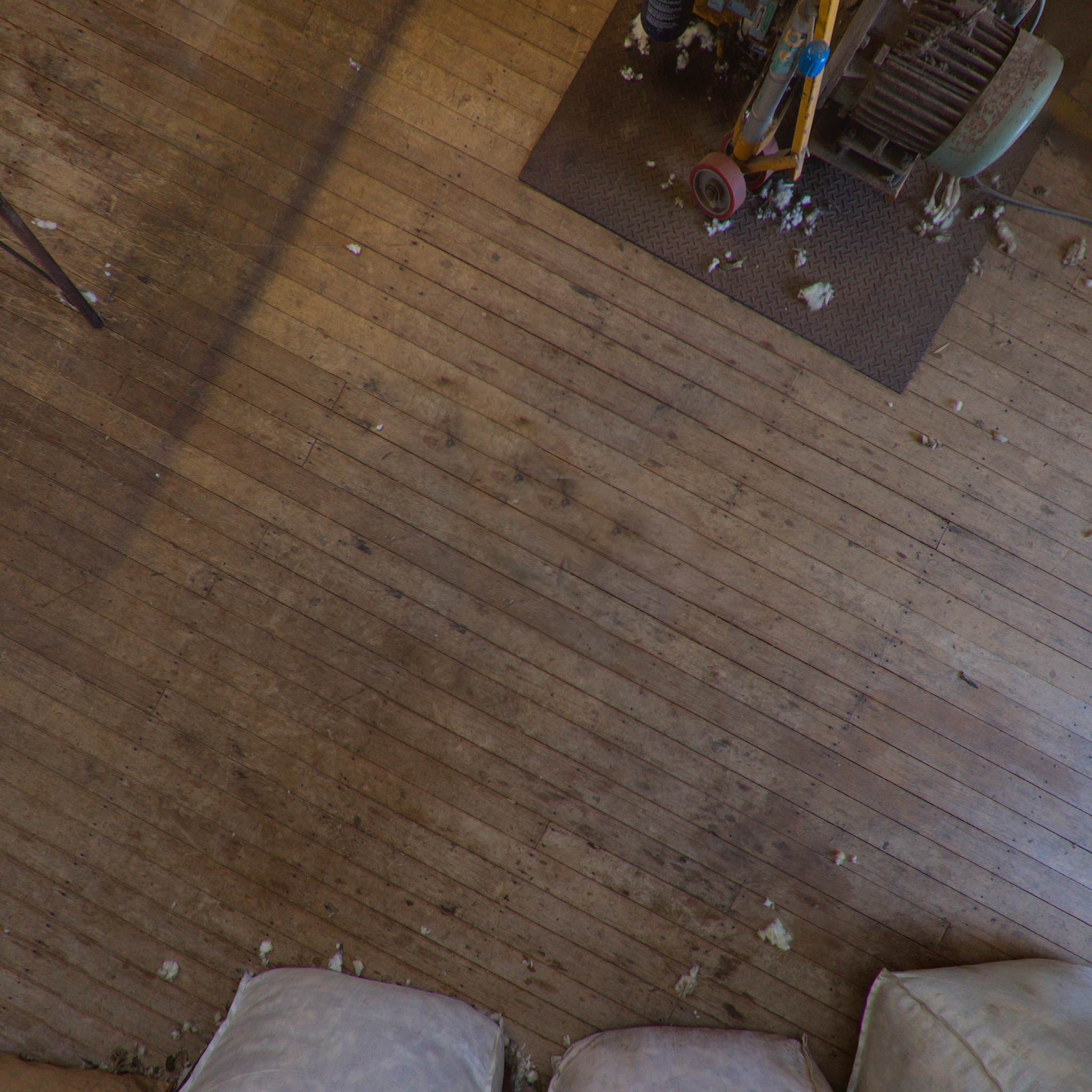
The main trick is the wrapping of the mesh triangles between the left and right edge of the equirectangular mesh. These are the triangles down the middle of the "back" face. Zooming in (click on image) on the image above illustrates the edges that have been bisected by the wrap-around edge. A trickier aspect is the center grid cell on the top and bottom face, these two cells get spread across the whole of the top edge (North pole) and bottom edge (South pole). Testing is more readily performed by starting with an equirectangular image, dicing into cube maps, applying each to the mesh above and checking one gets the same result. The input equirectangular is the shearing shed as below. 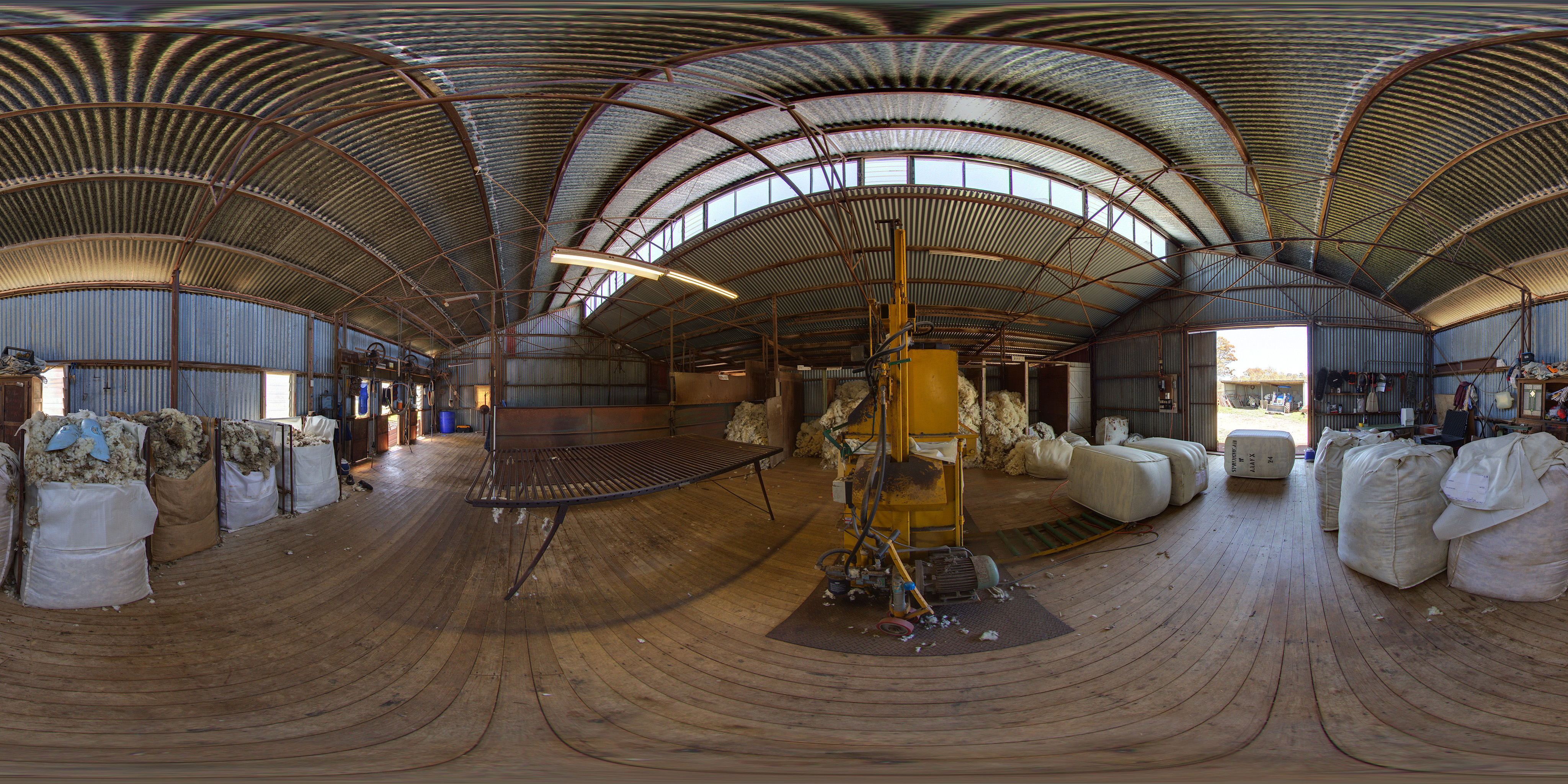
The cube map textures are shown below.
The following shows the textures applied to each mesh. 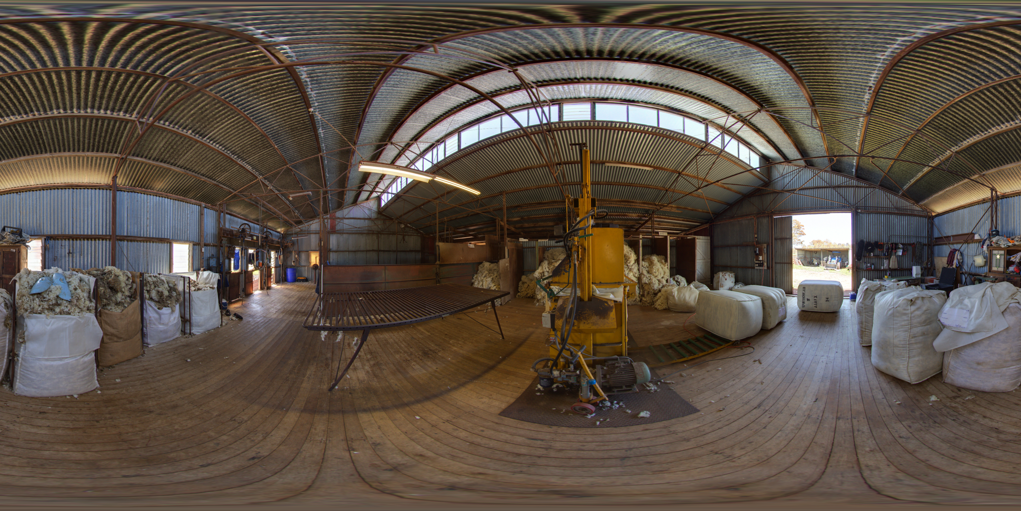
As expected there are issues at the two poles. This occurs for various reasons but one include the type of interpolation realtime engines perform. In this case the texture fragment on the top and bottom edge needs to be interpolated across the entire width of the image. The issue is also apparent in the triangles approaching the poles. There are a variety of ways of reducing these issues, they generally involve creating a higher density mesh or applying a different tessellation. |