Mirror effects for 360 viewingWritten by Paul BourkeJune 2022 Mirrored sphere at nadir
It is not uncommon for equirectangular photographs to have the tripod visible at the south pole of the image, the nadir. There is a skill in removing this blemish using automatic tools like context aware filling, semi-automatic clone painting, copy/paste from nearby regions or purely manual painting. The degree to which that area can be repaired depends on the imagery, some cases are easier than others, but it can also depend on how much time one can afford to spend. For those times when it is either difficult or time consuming there are other strategies, two common ones are to place the photographers name and/or company as a circular disk. Another approach is to place a circular little planet patch. One feature of both these is that there is invariably a disconnect between the equirectangular and what one sees at the nadir. The following removes the discontinuity by placing a perfectly mirrored sphere at the base of the equirectangular sphere and re-rendering the equirectangular image. A side view is shown below, the exact position and size of the mirrored sphere can be adjusted to control the size of tripod coverage required, and the degree of continuity with the surrounding imagery. 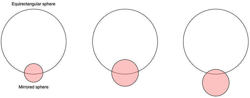
For continuity, the contact circle of the mirrored sphere with the equirectangular sphere should just be visible from the center of the equirectangular sphere. For an equirectangular mapped onto a unit sphere and a mirror sphere of radius R, then the distance L from the origin to the mirror sphere for perfect continuity is given by
As an example, the following is what the final equirectangular image looks like after the mirrored sphere has been added. In this case the radius of the mirrored sphere required is quite small, 0.25. 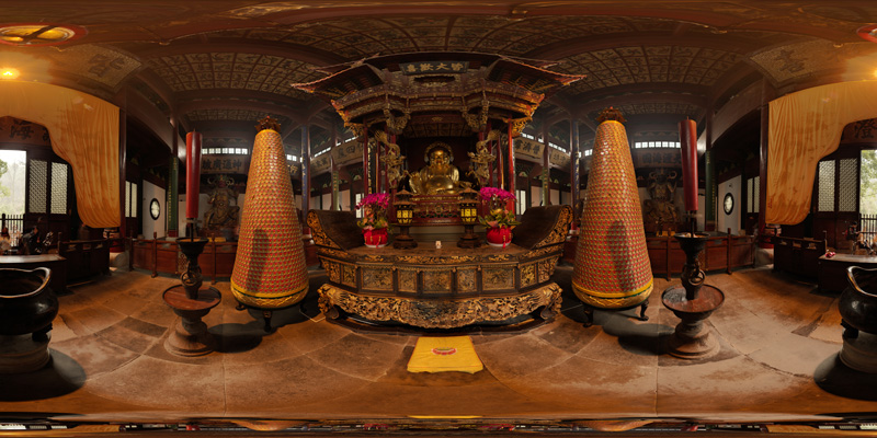
Looking straight down is shown below. 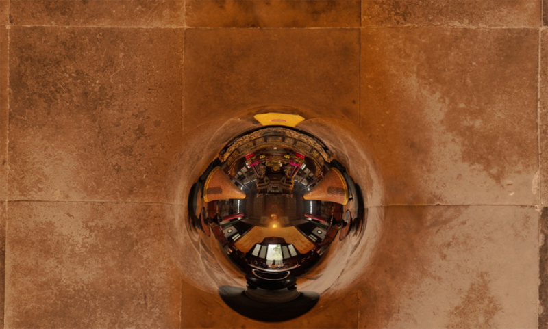
Mirrored plane effect
The following is a "funky" effect to fill in large unusable areas at either the north and south poles, or to add vertical extent to cylindrical panoramas which have a limited vertical field of view. One places perfectly mirrored planes towards the top and bottom of the equirectangular sphere, or the cylinder onto which a cylindrical panorama is wrapped. 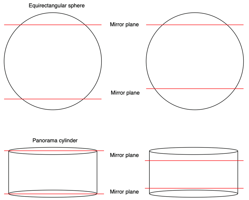
As with the mirror ball above, the exact positioning of the planes can control the final appearance of the rendered equirectangular. As an example consider the cylindrical panorama below. This is wrapped onto a cylinder centered at the origin. If the radius of the cylinder is 1 then the height is given by 2 pi H / W where H and W are the width and height (in pixels) of the panorama respectively (assuming square pixels). 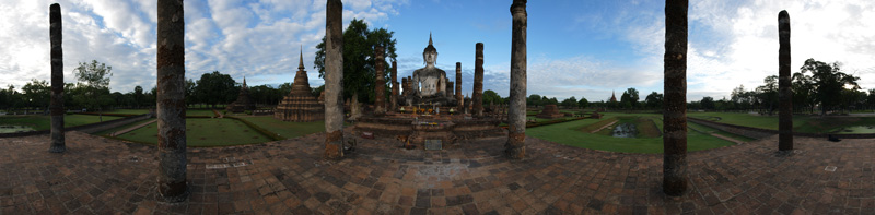
The resulting equirectangular is as follows. 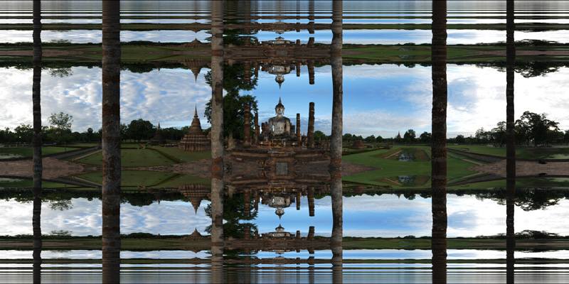
A navigable version can be found here. The above is an example with a cylindrical panorama where there is obviously a minimum height for the planes. For an equirectangular source image there is more scope for the height of the planes. The following example is based upon an equirectangular image wrapped onto a unit sphere and with mirror planes at +0.3 and -0.35. 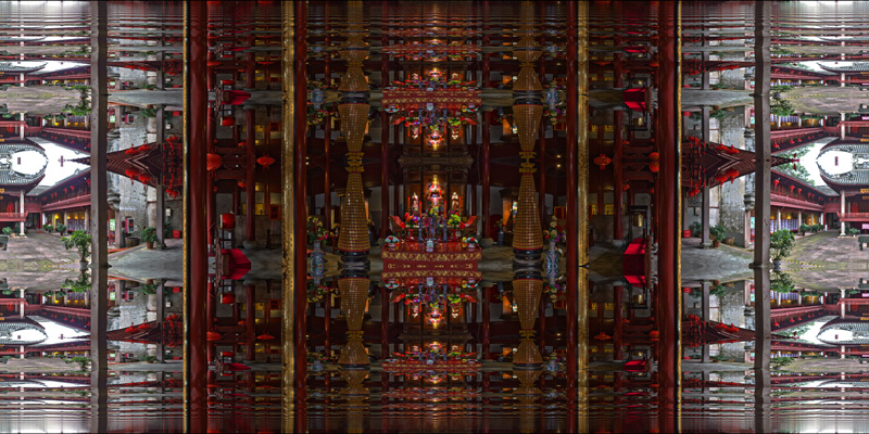
A navigable version can be found here. A view looking upwards is shown below. As can be seen this type of mirroring works best when there is some vertical geometry that mirrors well, in this case, the columns. 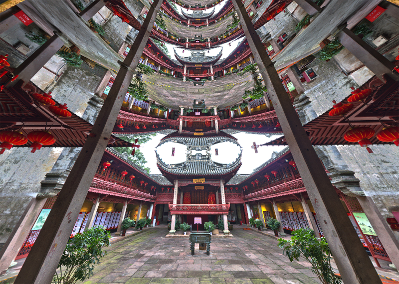
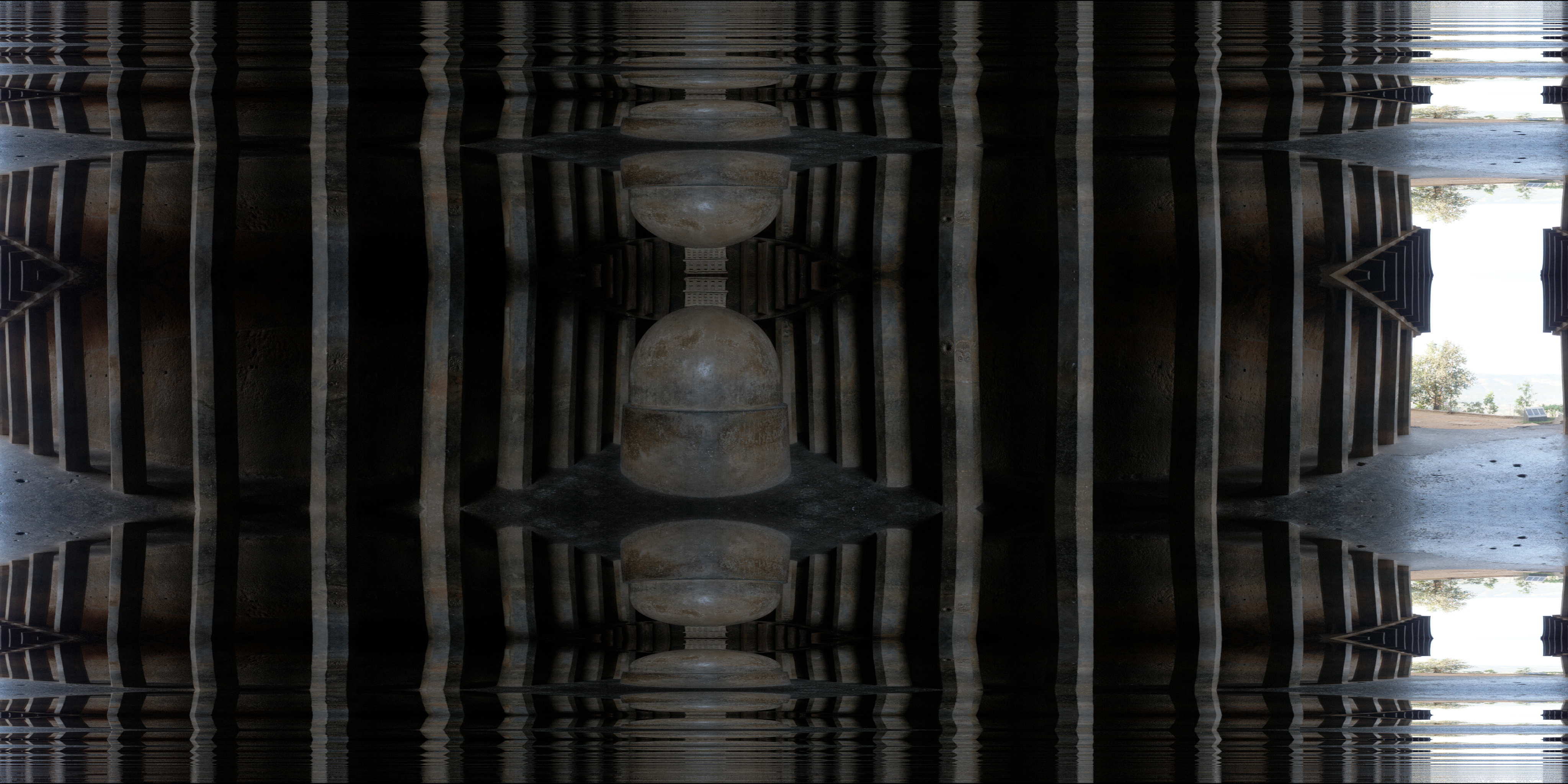
As an extension one can use vertically translated large spheres of various radii to control the degree of repetition of the mirrored sections. The more curved (smaller) the spherical mirrors the more compressed the mirrored layers, the plane case presented earlier is the limit as the mirror sphere radius increases to infinity. 
In the cylindrical case the minimum height L of the spherical mirror of radius R, assuming a unit radius cylinder and panorama height H and width W, is given by
Another extension and interesting effect can be achieved by slightly tilting the mirror planes or mirror spheres, the effect of this will be left as an exercise for the reader. One can apply the same top and bottom mirror planes to cubemaps, see example below. Here, the 6 cube maps are mapped onto the correct 6 square polygons surrounding the central camera. The planes can be located at a user selected height above and below. 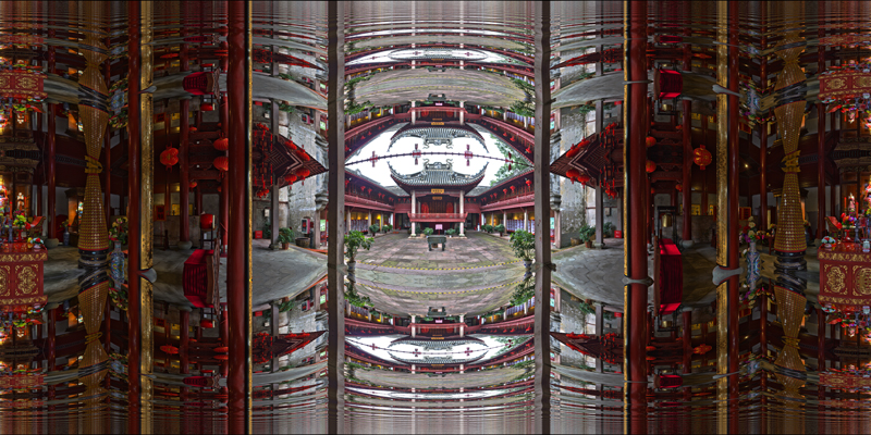
A navigable version can be found here. When looking around the horizon (no mirror) the geometry looks correct, the planar nature of the faces is only revealed when looking up and down.
 Navigable version
|