Image warping for projection onto a cylinder
(Including stereoscopic)
Written by Paul Bourke
December 2004
|
|
Introduction
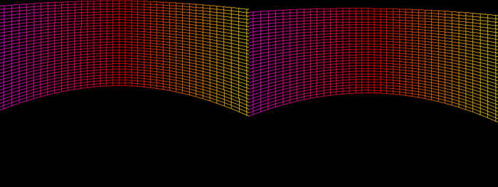
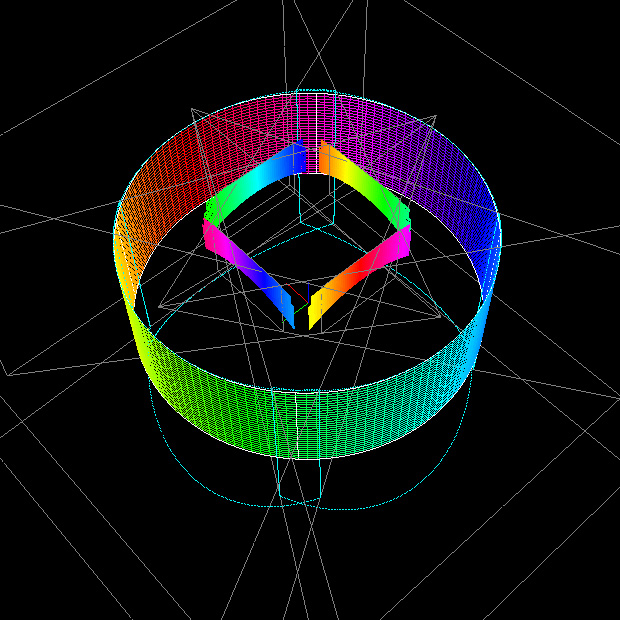
In general, given a cylindrical surface and an arbitrary projector position
and orientation angle, the projected image as it appears on the cylindrical surface
will look distorted, see figure 1 and 2. In addition there may be parts of the
image plane that do not lie on the cylindrical surface (shown in grey below) and
it may be necessary to tile the images and therefore
edge blend between adjacent
images (shown in blue below).
Figure 1: Projecting standard mesh (View 1).
Blue is edge blend region.
Grey is outside the screen area.
|
|
Figure 2: Projecting standard mesh (View 2).
|
|
|
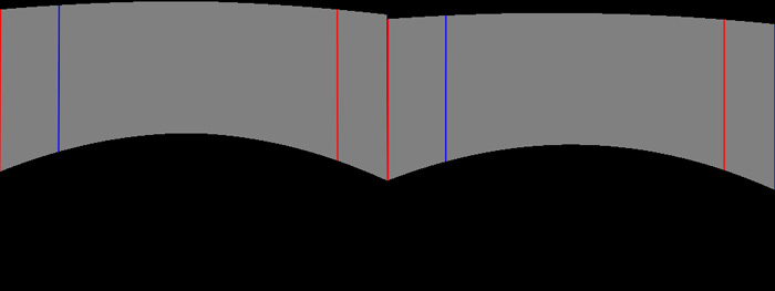
It is possible to warp the projected image so that the image as it appears
on the cylindrical surface looks undistorted to an observer at the center
of the cylinder. Figure 3 and 4 show a warped grid and the correct result
on the cylindrical surface. With current graphics hardware this warping can be
performed in real time, in this case the input to the warping stage is a
cylindrical panoramic image. The exact warping function can be calculated by
simulating the physical system and tracing rays from the projector, taking
into account the lens, and finding where that ray hits the cylindrical surface.
Given that information, the coordinates of the panoramic image that should be
at that point on the cylinder can be calculated. While the warping for some
projector/lens/screen arrangements can be calculated analytically, this
simulation approach is most appropriate for dealing with arbitrary arrangements.
Figure 3: Projecting corrected mesh (View 1).
|
|
Figure 4: Projecting corrected mesh (View 2).
|
|
|
Example
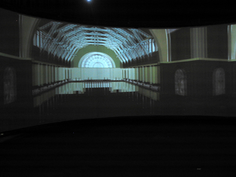
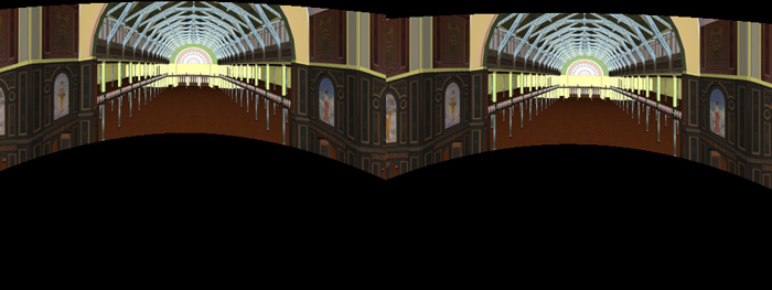
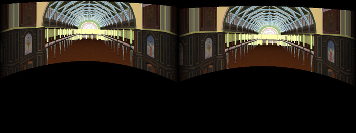
The following is an example using a rendered panoramic from a computer model
of the Royal Exhibition Building in Melbourne, Australia. In figure 6 the
warped image can be seen on the projection plane and figure 5 shows the
undistorted image as it would appear on the cylindrical surface. In this
environment the full cylinder will be illuminated with 4 projectors, each
edge blended for a continuous cylindrical panoramic image.
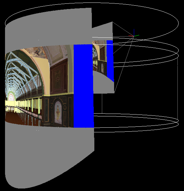
Figure 5: Projecting corrected mesh (View 2).
Royal Exhibition Building, Melbourne.
|
|
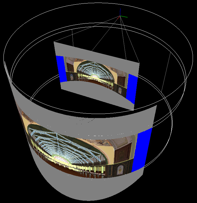
Figure 6: Projecting corrected mesh (View 2).
Royal Exhibition Building, Melbourne.
|
|
|
Screen dumps from single computer, a stereoscopic pair
Warping mesh and texture coordinates
Stereo pairs (left and right eye) mapped onto textured mesh
Edge blend zones

Gamma corrected edge blend
Final image with edge blend zones
|
|
|
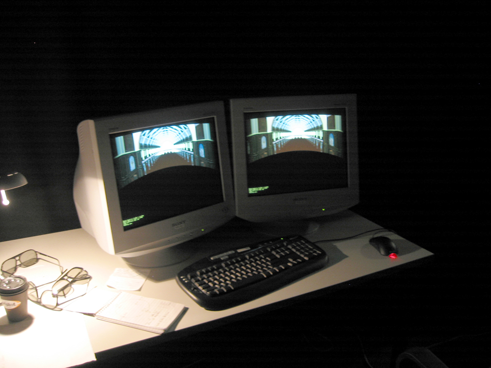
Example: 360 degree stereoscopic display

The following is one of 4 computers, each computer presents the left and right
eye, edge blended pair.
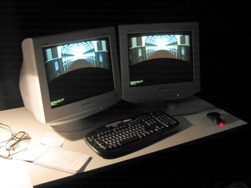
Each display is connected to a single projector,
stereo is achieved using passive polaroid filters on the projectors that
match the filters in the polaroid glasses.
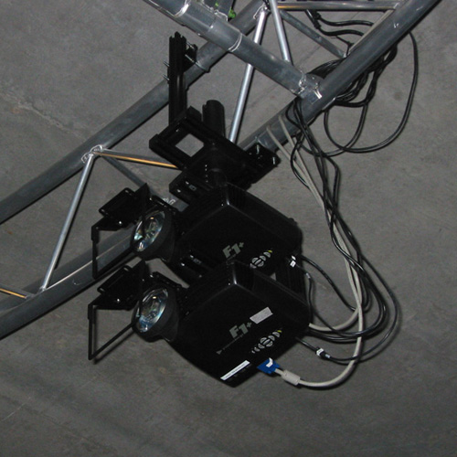
In total, 4 projectors for 360 degree coverage, 2 projectors per eye.....8
projectors in total.
|
|