Direct rendering of warped fisheye views for spherical mirror projectionWritten by Paul BourkeJuly 2004
In this document I discussed a low cost system for projecting into planetarium domes using a single projector and a spherical mirror. The approach taken in that document is that content creators would render to fisheye images which would in turn be warped to create the correct views for the spherical mirror projection. This warping can be performed off-line or built into the movie playback software, (warping on the fly). Here an alternative direct rendering method is introduced, the correct warped image is created directly from the rendering (generally raytracing) process by simulating the projection geometry. The general principle is straightforward, the dome projection consists of a projector and a spherical mirror, the projector is replaced with a matching virtual camera in a rendering software thus creating the correct image. Care needs to be taken to replicate the projection environment accurately, for example, using the correct radius mirror, using the same aperture on the camera as the aperture of the projector, etc. One unfortunate characteristic of data projectors is they usually project off-axis and raytracing packages don't always support that. This can be compensated for by rendering with a larger on-axis frustum and trimming the result.
Direct rendering technique for fisheye projectionExample using PovRay
Written by Paul Bourke Introduction There are a number of techniques that can be employed to render content for non standard displays such as domes. Only in rare cases does the rendering software support direct rendering that will take into account the necessary distortion of the projector and projection surface. In other cases one needs to create the correctly distorted image from simple perspective or orthographic projections supplied in all rendering packages. This document will describe one method that is rather sneaky and will work with "any" package although it does suffer from some problems. The technique involves creating a mirror or lens as a geometric primitive that is placed in front of a camera. The mirror is designed precisely so that the captured image, when projected, will look correct on the intended projection screen. Cube methodBefore considering the mirror method it should be pointed out that there are other ways of creating such content. One very popular method is to render a 4, 5, or 6, 90 degree perspective views along each orthogonal axis forming a cube (otherwise known as an environment map). This has been discussed here and applied to creating content for planetariums here. The basic setup of the cube is shown below. Some people choose to render 4 faces, most people choose 5 because the bottom half of the 4 surrounding faces can more easily be excluded from the rendering.
An example rendering in the format of the unfolded cube is shown below on the left. The image ready for projection in the dome is shown on the right. Note that a full dome image can be created from the cube but in the case of the some systems (Elumens VisionStation) the bottom quarter is not used.
Mirror method
As mentioned, the basic approach is to design a mirror and capture the image reflected from it. The basic setup is shown below, the "final camera" is the one being used with the mirror, the "test camera" is used for testing purposes, it may be a wide angle or angular fisheye if that is supported. Of course the magic is in the design of the mirror which creates an image so that when projected through the hardware gives the correct view. In this case the lens has been calculated so as to work with an orthographic (parallel) projection. 
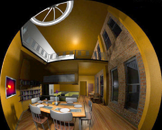
The test scene rendered as a fisheye and with the mirror is given below. The differences are not great and mostly occur in the mid regions, essentially the difference between a linear ramp and a sinusoid.
The PovRay source code for the above images can be found
here. The file
"lens.inc" contains the
mesh triangle primitives describing the lens, this includes vertex normals
to give a smooth surface without an excessive number of polygons.
The back of the mirror is placed at x=0 and it lies in the y-z
plane, it extends to about 0.4 at the thickest along the x axis.
   scale <SCALEFACTOR,SCALEFACTOR,SCALEFACTOR>
   translate <-0.41,0,0>
   matrix <UVD.x, UVD.y, UVD.z,
           UVR.x, UVR.y, UVR.z,
           UVU.x, UVU.y, UVU.z,
           VP.x,  VP.y,  VP.z>
For an example on how to use these files see "testscene.pov", the scene geometry for this was created using "makescene.c". Note that the mirror is a circular object and a black backing sheet is placed behind it to obscure any scene geometry around the edges. So while the mirror is perfectly reflective, the blocking sheet is perfectly black and absorbing.
Issues There are a number of issues/problems relating to this technique.
|