|
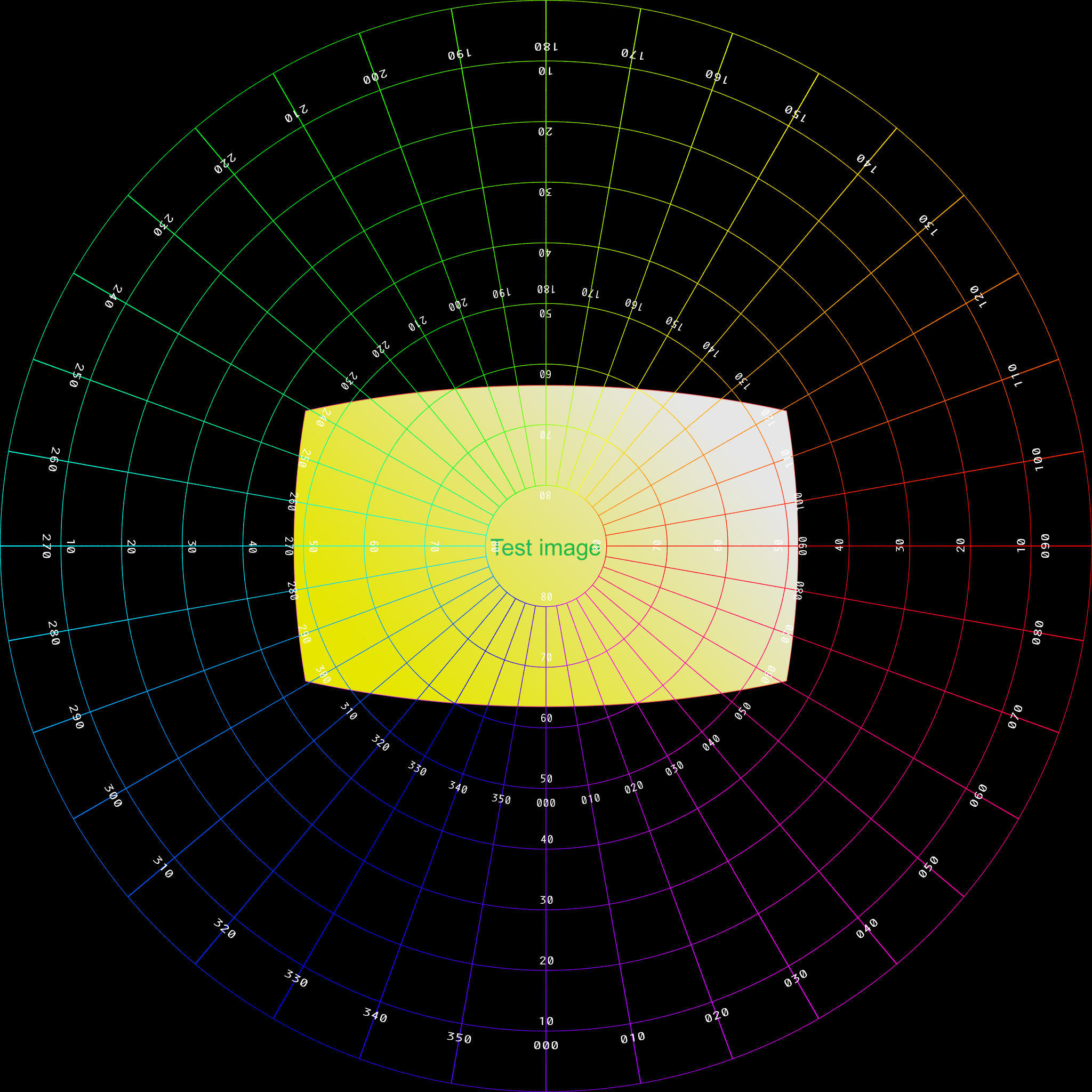
Test pattern
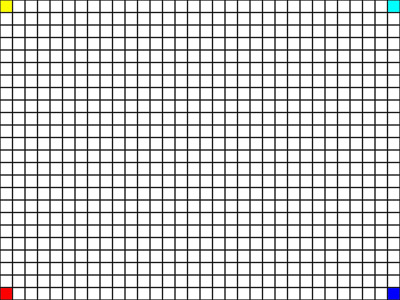
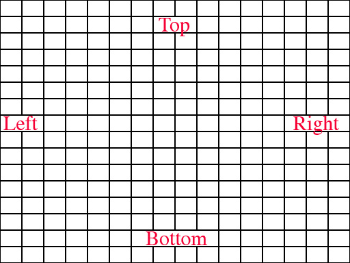
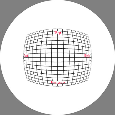
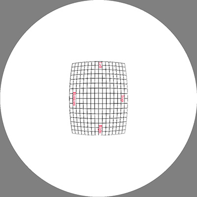
The image below was used as the initial test pattern, the results
for each of the panel positions is shown below (click on images for the full
size fisheye).
As expected there is quite
a bit of compression involved so good antialiasing is mandatory, in the
cases shown here a 3x3 adaptive antialias was employed.
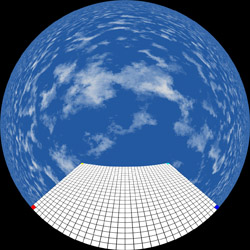
Upright
|
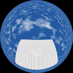
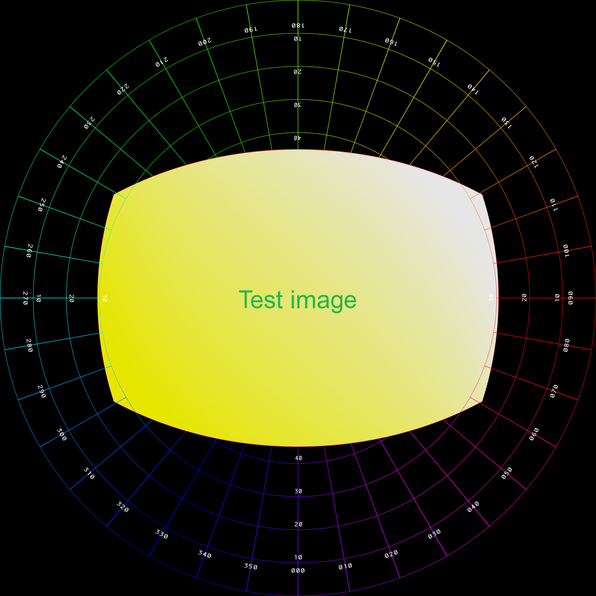
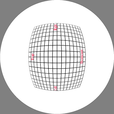
Rotate by 45 degrees
|

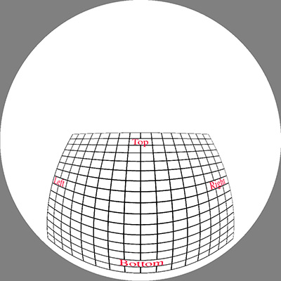
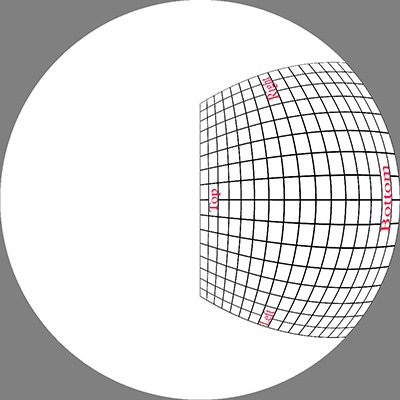
Rotate by 30 degrees
|
Another example - A slide from a KeyNote presentation
Slides for spherical mirror full dome projection
Slides to fisheye
Written by Paul Bourke
An alternative, April 2006
This utility maps rectangular images into a fisheye.
The rectangular image is placed on a plane that is centered on the north pole
of the fisheye (center). It can be scaled by moving the plane closer or further away
using the -d option. It is positioned on the fisheye by panning and/or tilting the
plane. The plane is always tangential to the sphere, one of many possible geometries.
The generated image contains an alpha channel to assist with compositing.
Command line usage
slide2fish [options] tgafile
Options:
-a n  set antialias level, default: 2
-w n  width (and height) of the fisheye image, default: 1024
-s n  distance away of the plane, default: 1 unit
-x n  tilt plane towards rim, default: 0
-z n  rotate plane about north pole, default: 0
-d    debug mode
Example
Input image
|
Default mapping, centered on fisheye.
|
Tilted down 40 degrees.
|
Panned by 90 degrees.
|
Tilted by 45 degrees, panned by 90 degrees
|
Panned by -90 degrees, moved further away (scaled)
|
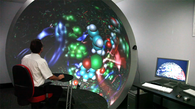
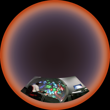
Mapping images into fisheye space so they appear to be on an upright cylinder in a planetarium
Written by Paul Bourke
April 2007
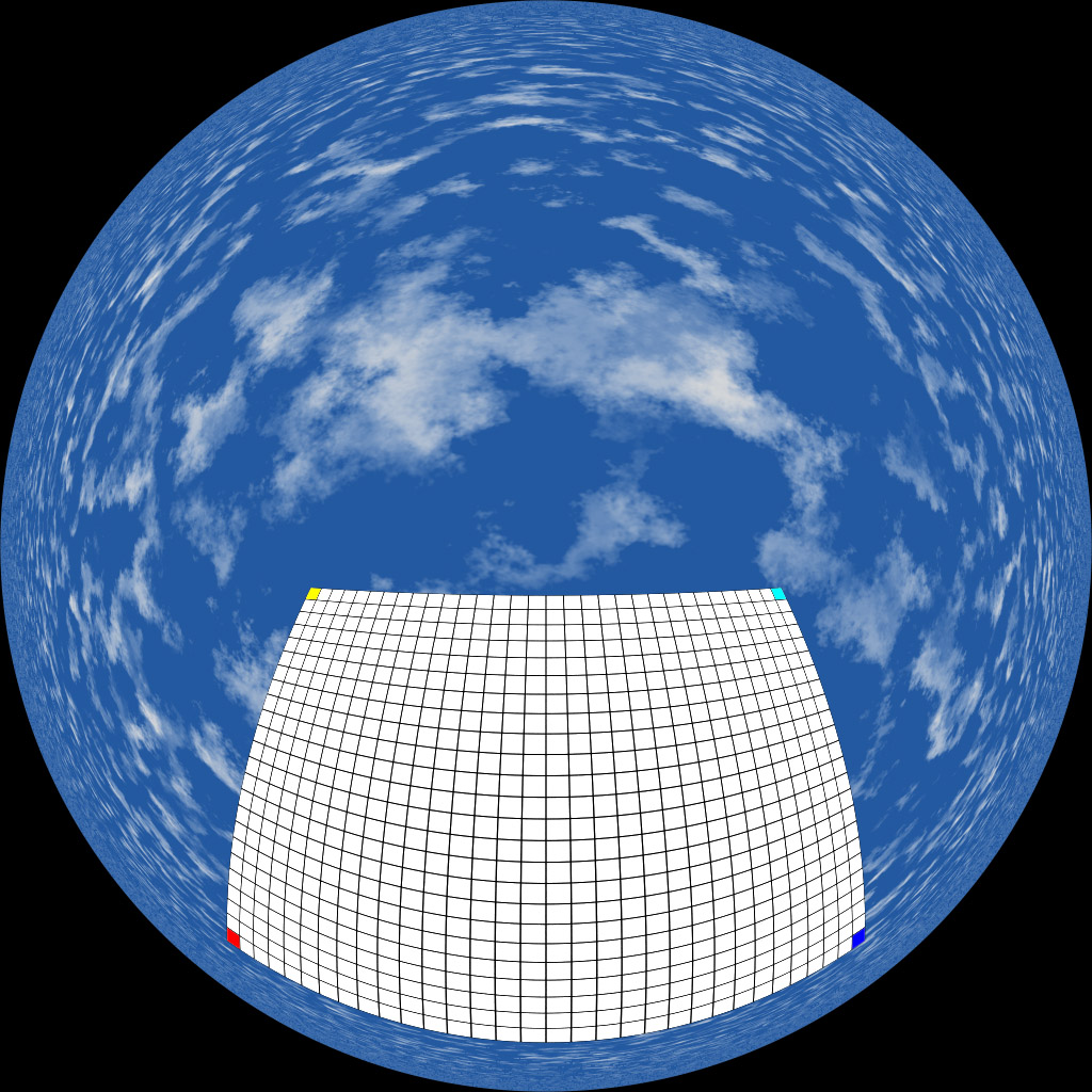
Aim is to map rectangular images onto a fisheye image such that when viewed in a planetarium
the images appear to be wrapped onto cylindrical sections.
Choose the width and position in longitude for the image, this is
theta1 and theta2. Also choose the latitude of the base of the image,
for example, it might be 0 if the image is to start at the horizon.
The image width and height are dx and dy in pixels.
We need to determine phi2 such that the image appears in proportion
and upright in the dome.
|
Figure 1
|
|
The images are imagined to be wrapped around a cylinder.
|
Figure 2
|
|
Define "r" as the radius of the hemisphere in pixels = dx / (theta2 - theta1)
Define dy1 as the height of the base of the image in pixels = r tan(phi1)
Then
tan(phi2) = (theta2 - theta1)(dy + dx tan(phi1)) / dx
For the final fisheye image the goal is to find r1 and r2, once they are
known the x,y normalised coordinates of the four corners of the image
rectangle in the fisheye can be determined, namely
r1(cos(theta1),sin(theta1)), r1(cos(theta2),sin(theta2)),
r2(cos(theta2),sin(theta2)), r2(cos(theta1),sin(theta1))
|
Figure 3
|
|
r1 = 2 (pi/2 - phi1) / pi
r2 = 2 (pi/2 - phi2) / pi
Notes
-
phi1 and phi2 are measured in the normal latitude sense in figure 1 and 2,
that is, 0 at the horizon.
It is traditional to measure angles in fisheye space from the pole (z axis)
rather than from the horizon. See the equations for r which contain terms
pi/2-phi1 and pi/2-phi2.
-
If the image is to start from the horizon (phi1 = 0) then the expression for phi2
is phi2 = atan((theta2-theta1) dy / dx)
-
When drawing the image as a texture using OpenGL say, one needs to compute smaller
quads over subsections of the longitude range.
PovRay, or any other 3D rendering engine
Written by Paul Bourke
Update: June 2010 and February 2016
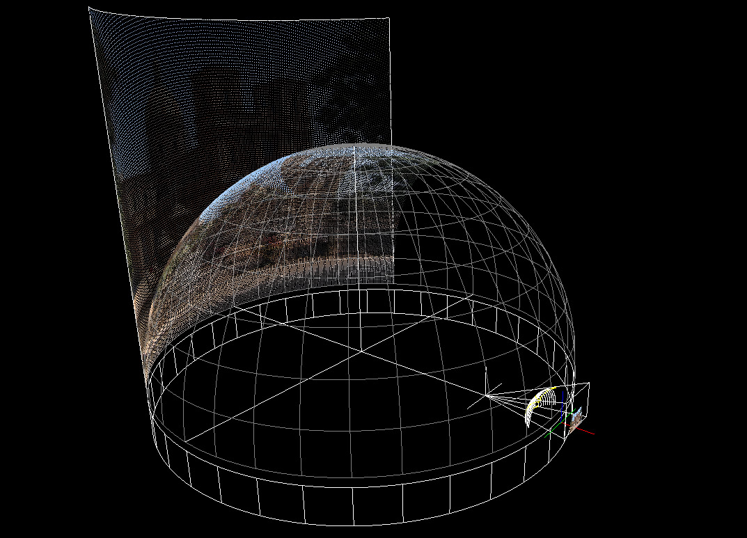
Of course one can also accomplish this using your favourite 3D rendering/animation
package as long as it supports fisheye rendering. Simply create the geometry you wish
the image to be mapped onto in a 3D scene and render with a fisheye lens on a
appropriately aligned camera. As example
of this using PovRay is presented here:
pov_billboard_4fisheye.zip.
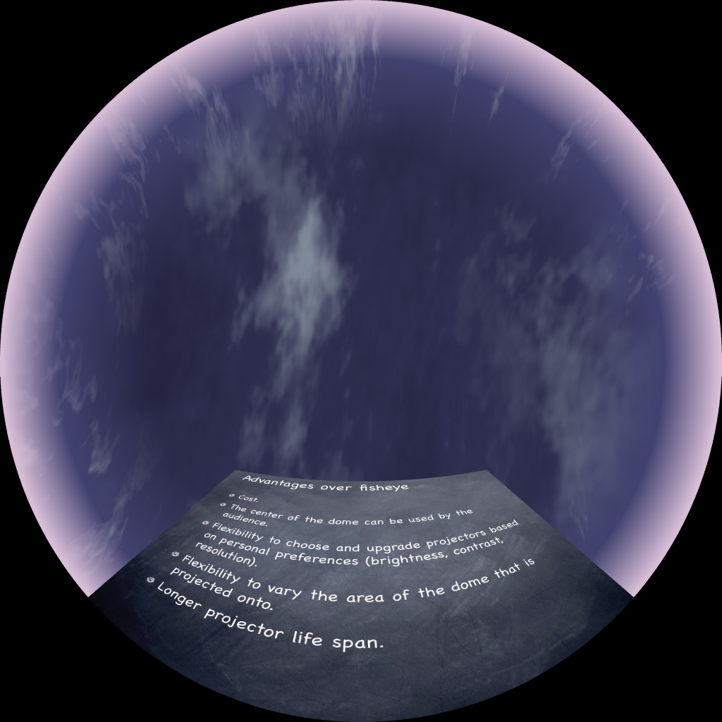
This approach makes it easy to animate the texture panels, the same approach is
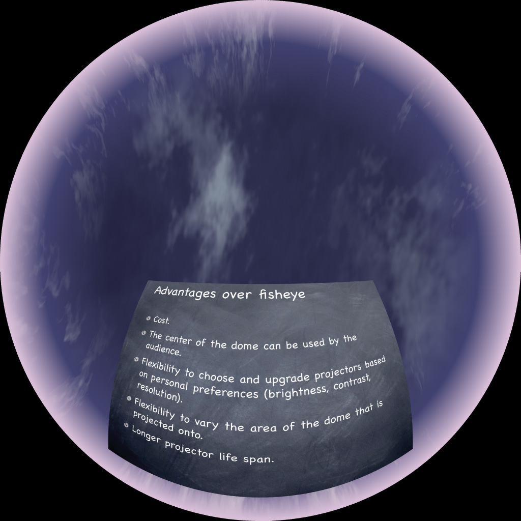
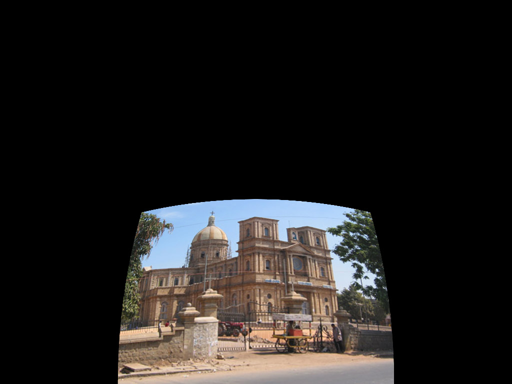
often used for text within a fulldome render. The example provided here takes the image below
on the left and renders the image on the right, in a dome this will appear as a vertical
pane.
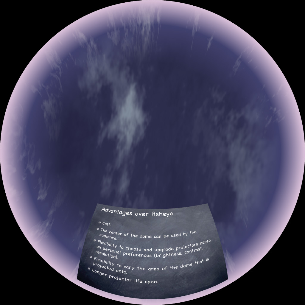
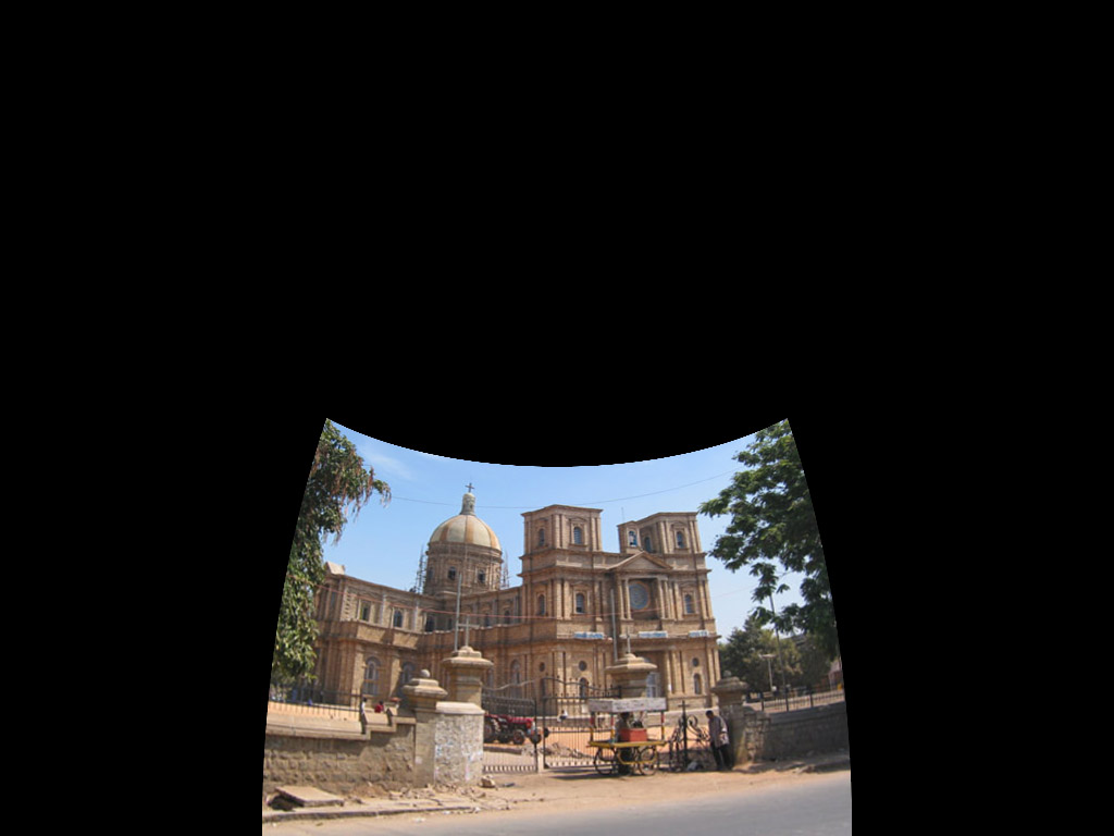
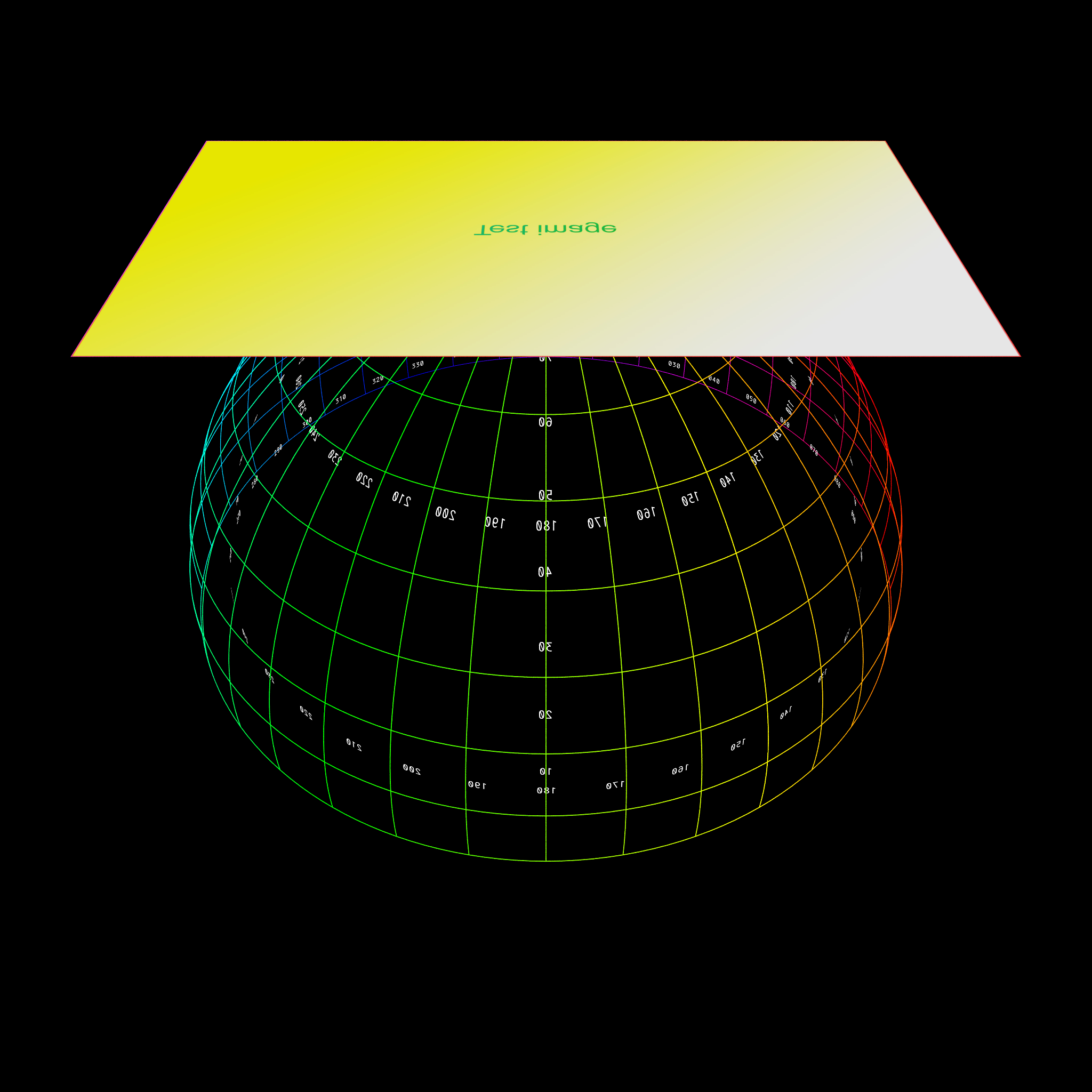
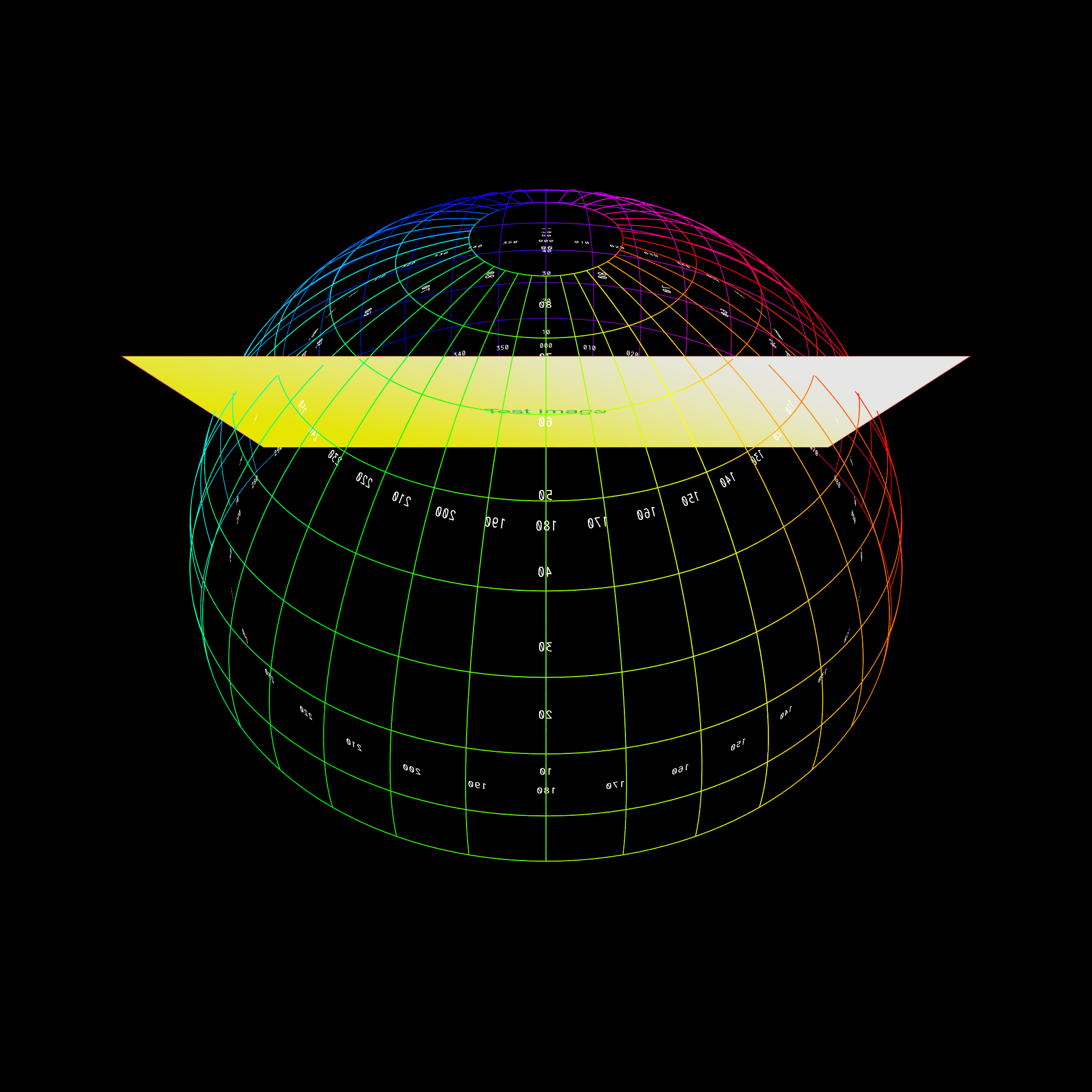
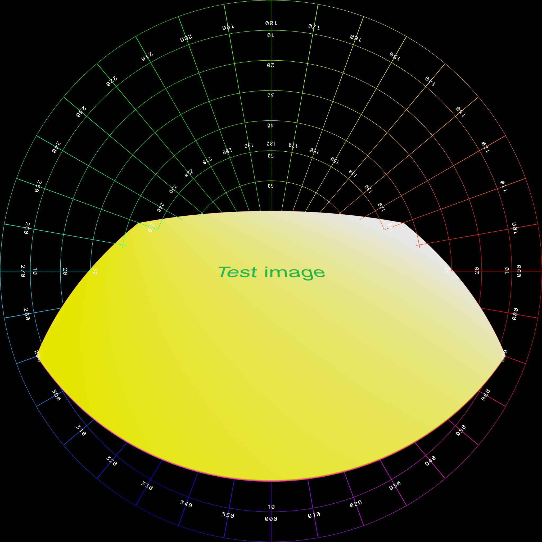
Further examples below, the left shows the plane positioned, scaled, angled with respect
to the dome, represented as a polar grid.
The right shows the result rendered into a fisheye.
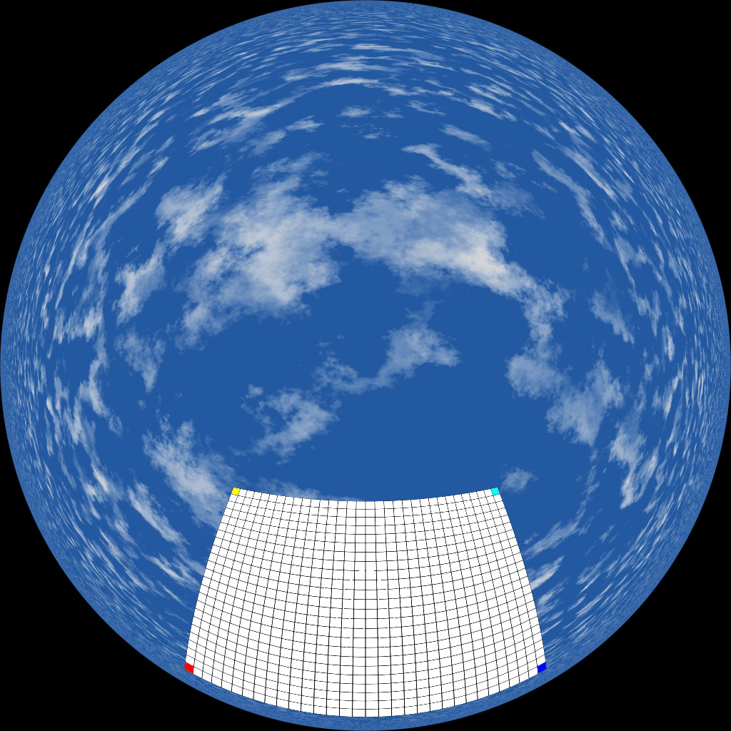
Lowered in the dome, brought closer to the viewer.
Rotated about a single angle.
|