DomeLab technical documentationWritten by Paul BourkeOct 2015
The following describes various technical aspects related to content delivery on Domelab, an 8 projector (2560x1600 pixel resolution each) fulldome system at the University of New South Wales, Sydney. It includes how so called "master" fisheye frames are diced, how audio tracks are mapped, how movies for each projector are encoded, the theory behind the dicing/warping/blending and finally how to create realtime content in the Unity game engine. Movie playbackFisheye movies are played in Watchout by dicing up the square fisheye frames into 8 (the number of projectors) pieces each 2560x1600 pixels (the resolution of the projectors). The typical fisheye resolution to optimise the dome projection resolution is 4Kx4K, these frames should be provided as images in a lossless image format, commonly TGA or PNG. The following describes this dicing process and then the geometric warping and edge blending required if some other playback system is to be employed, or if the reader is simply interested in how things work. Dicing files
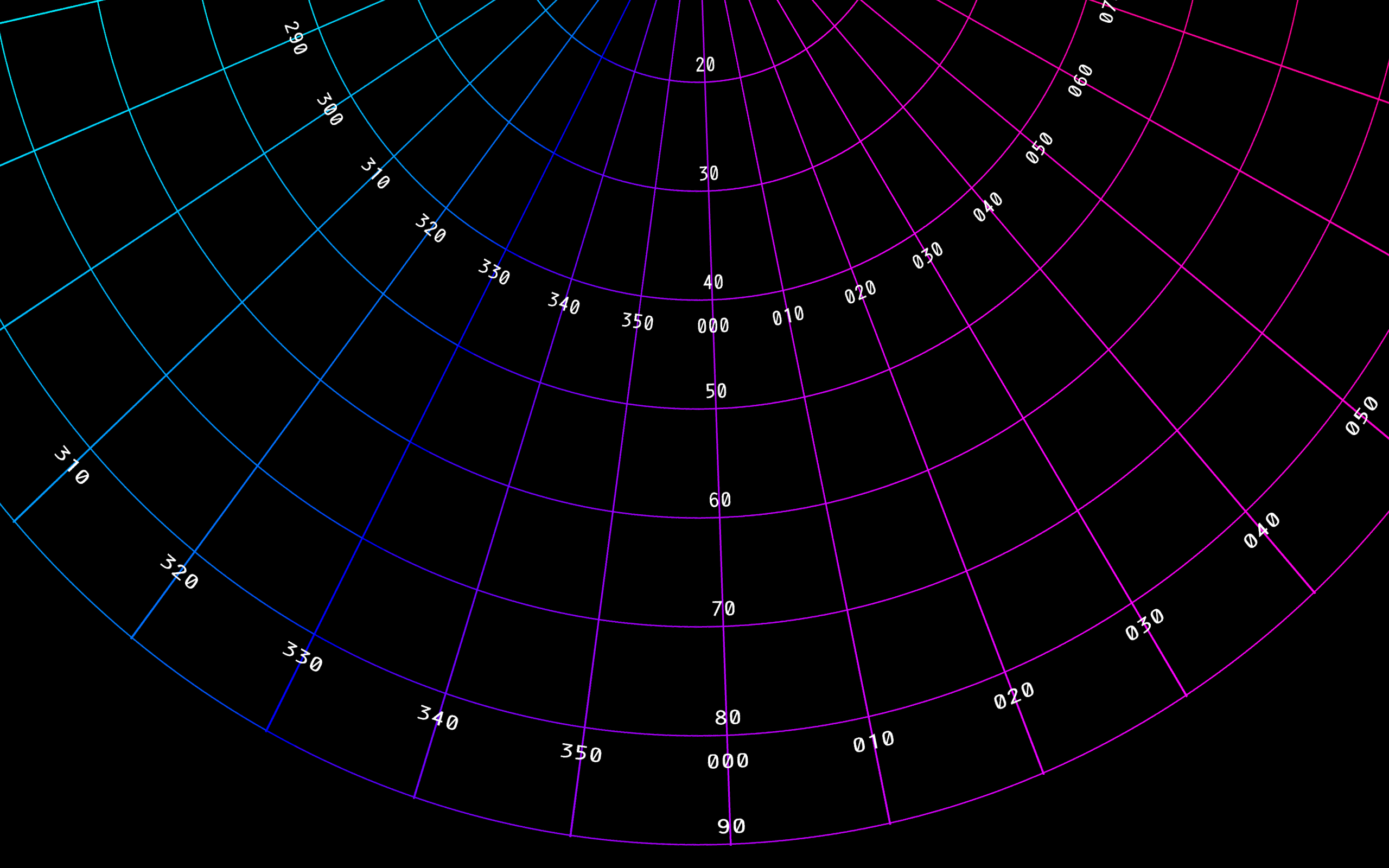
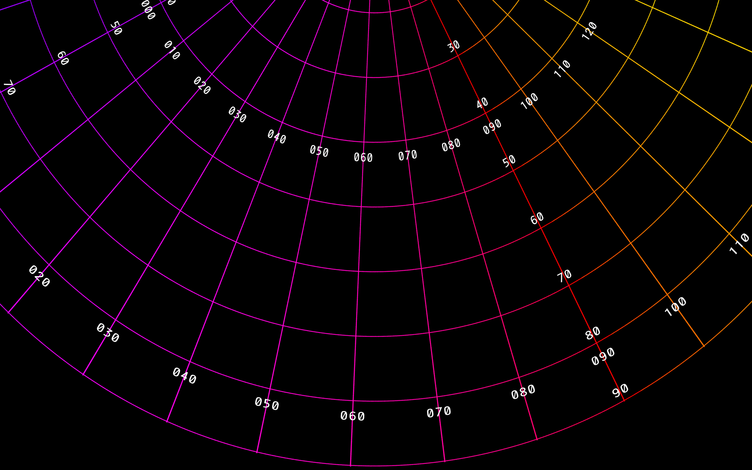
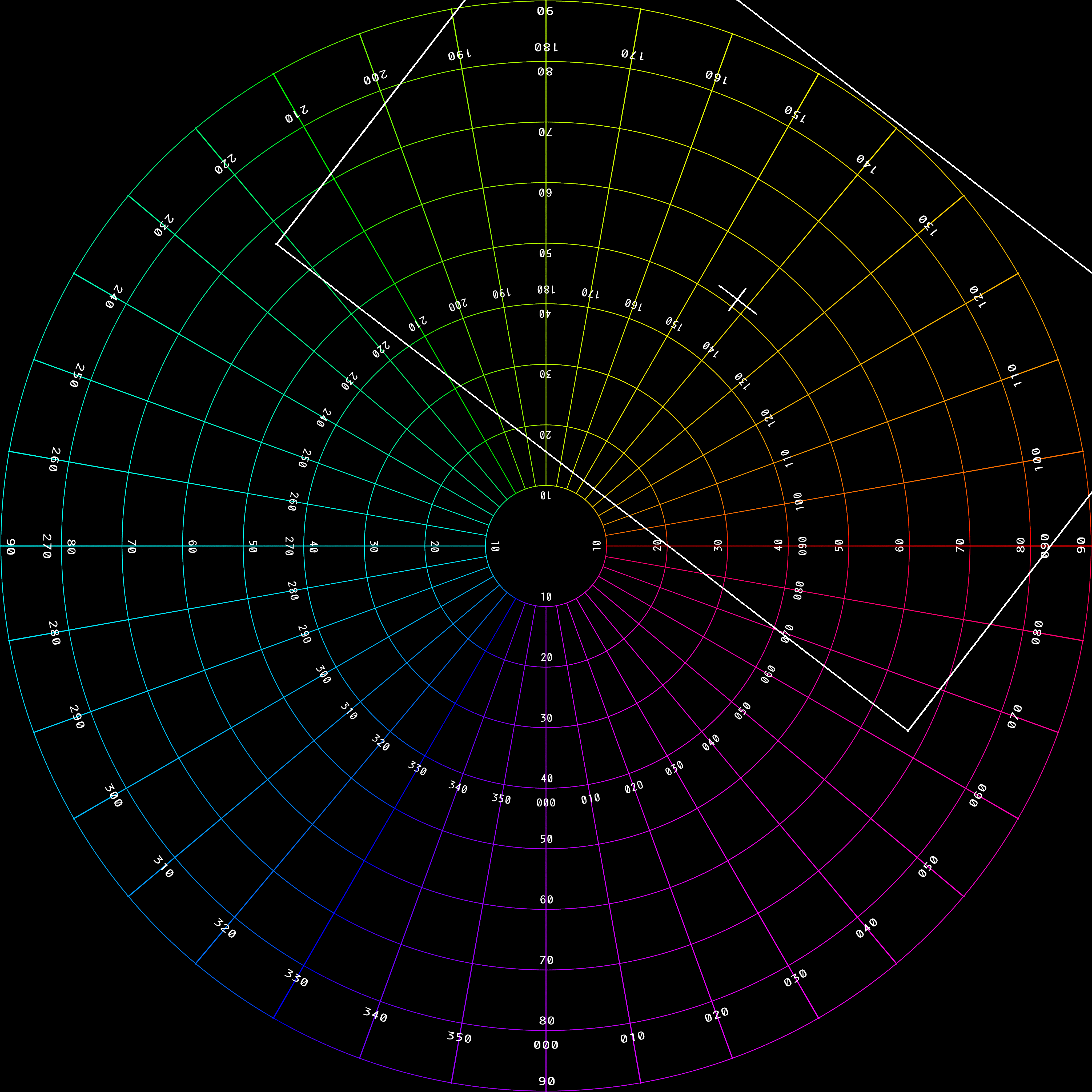
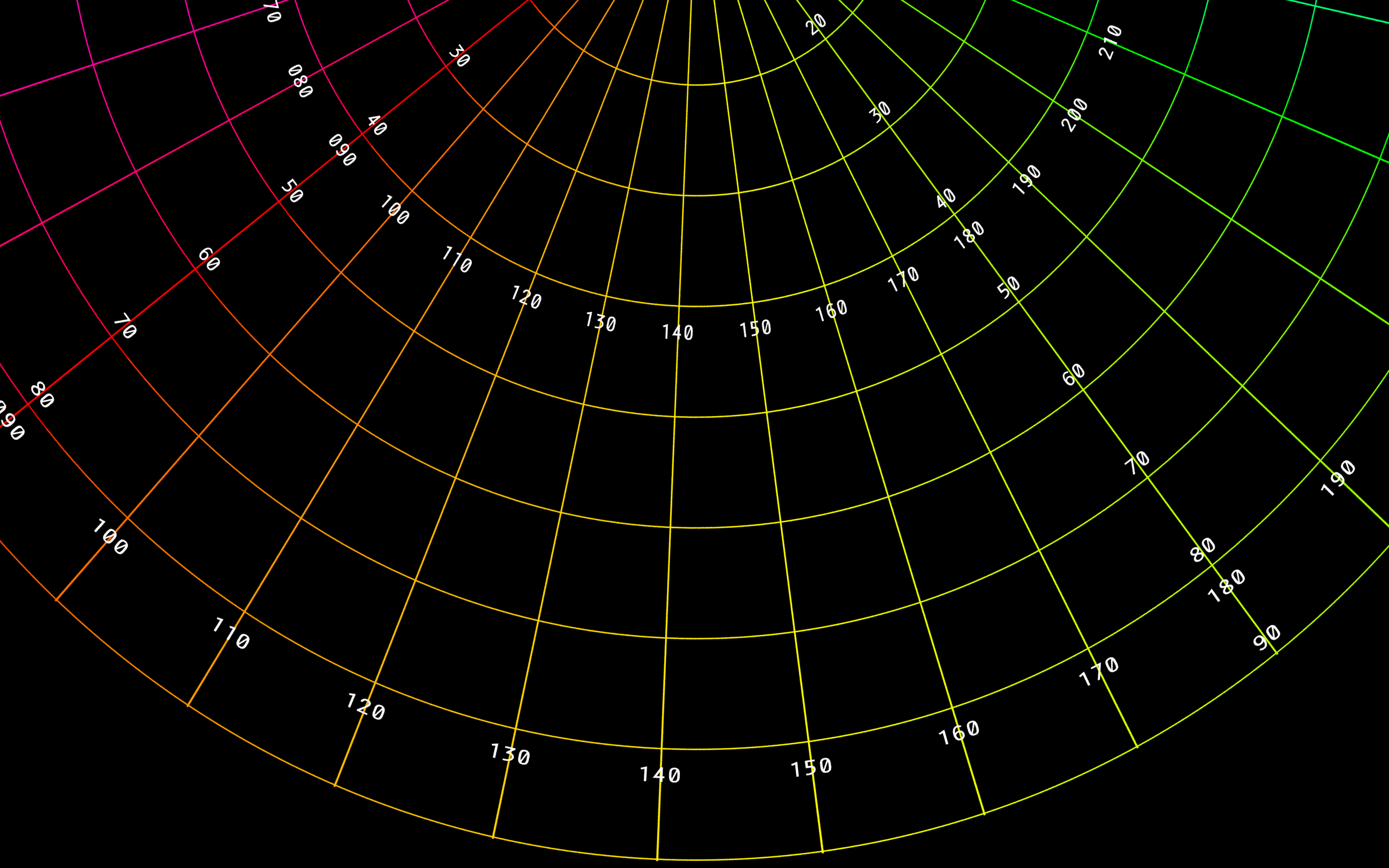
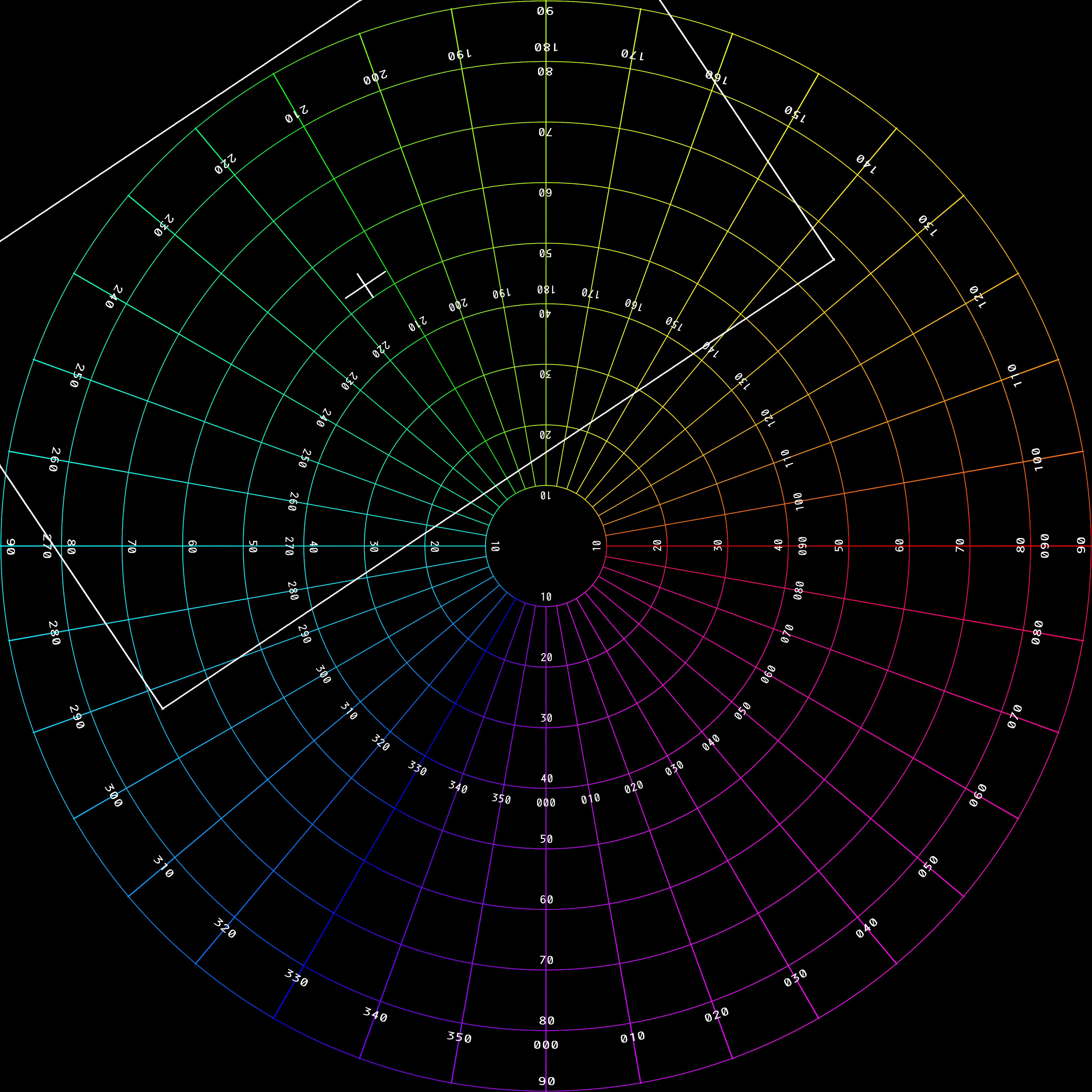
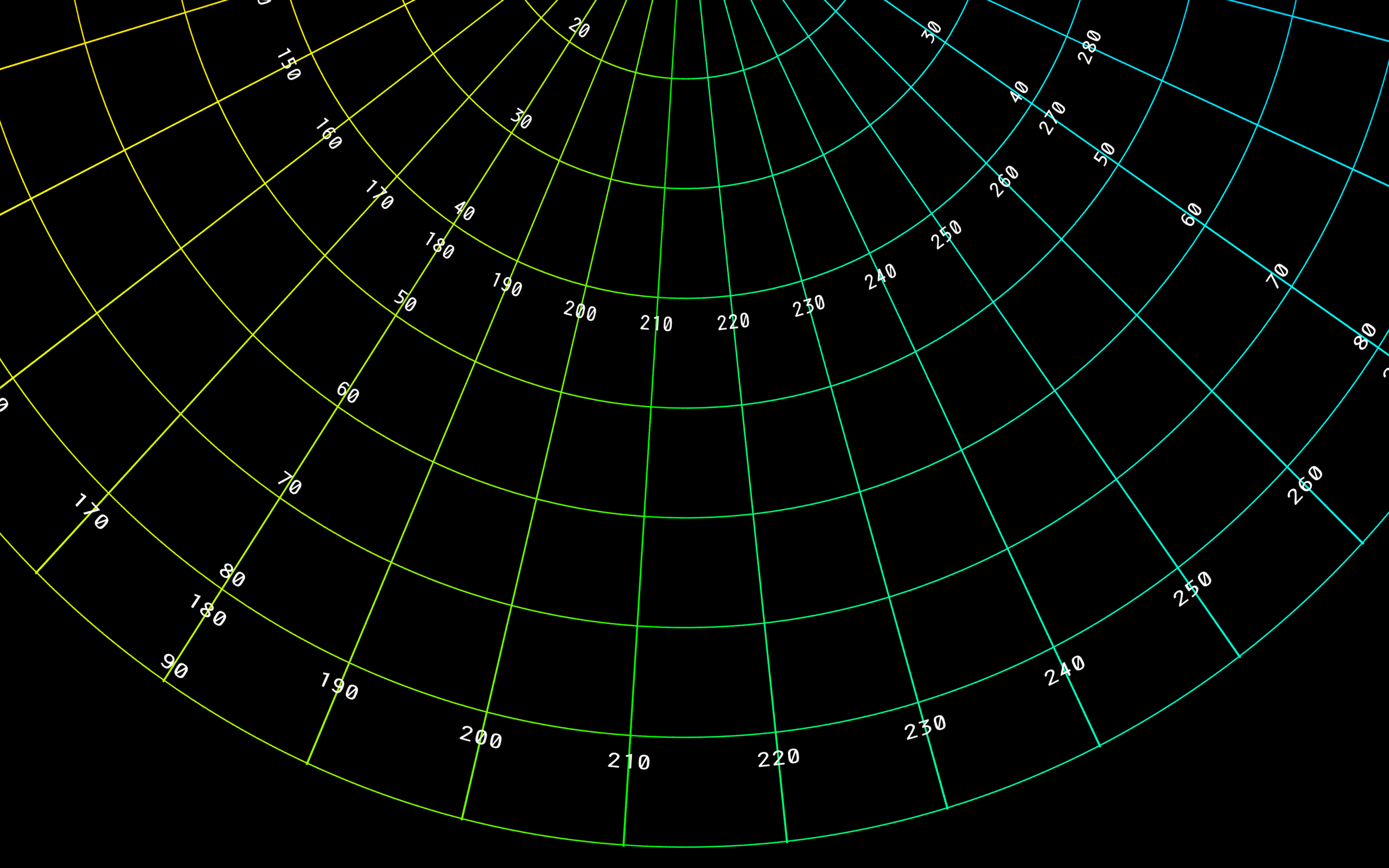
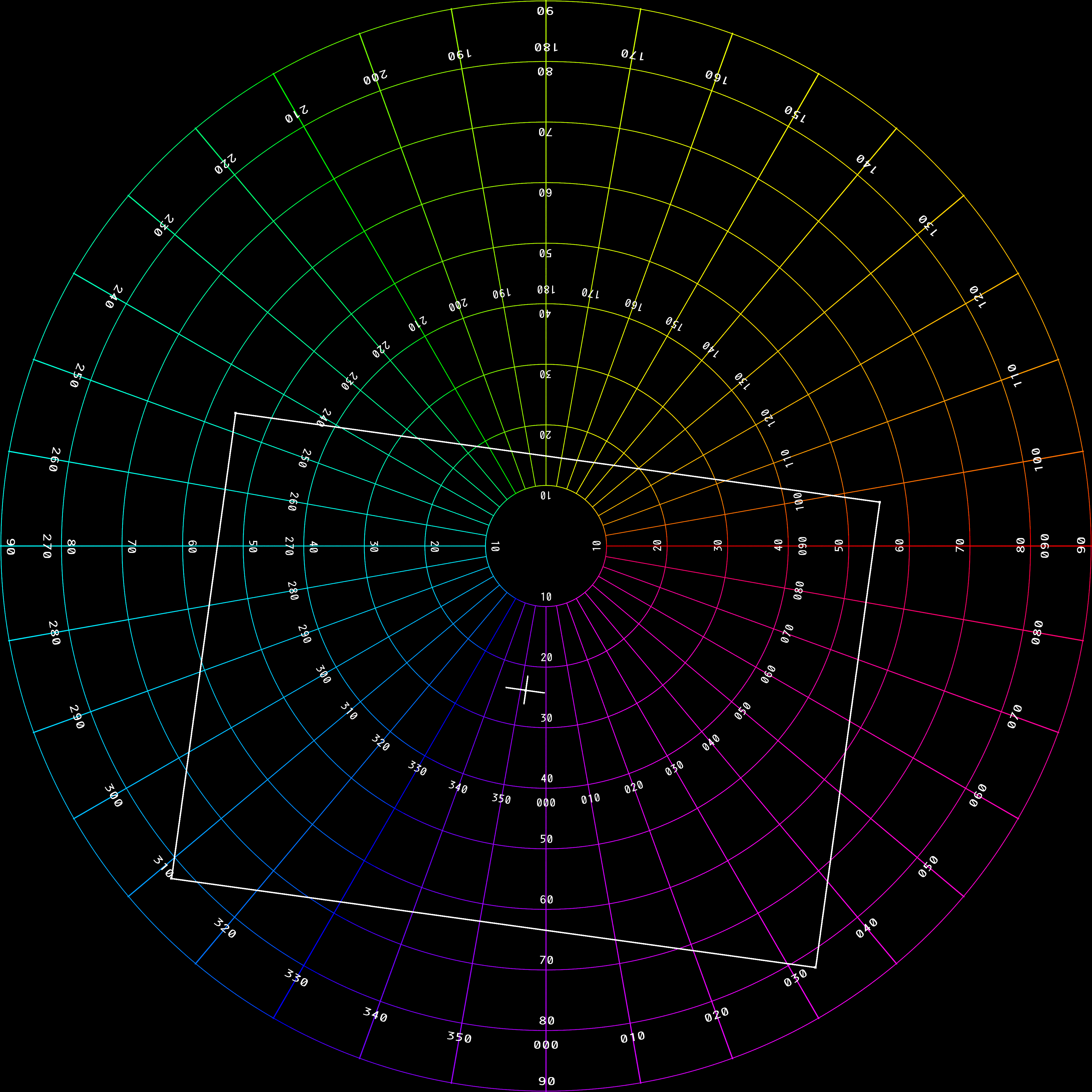
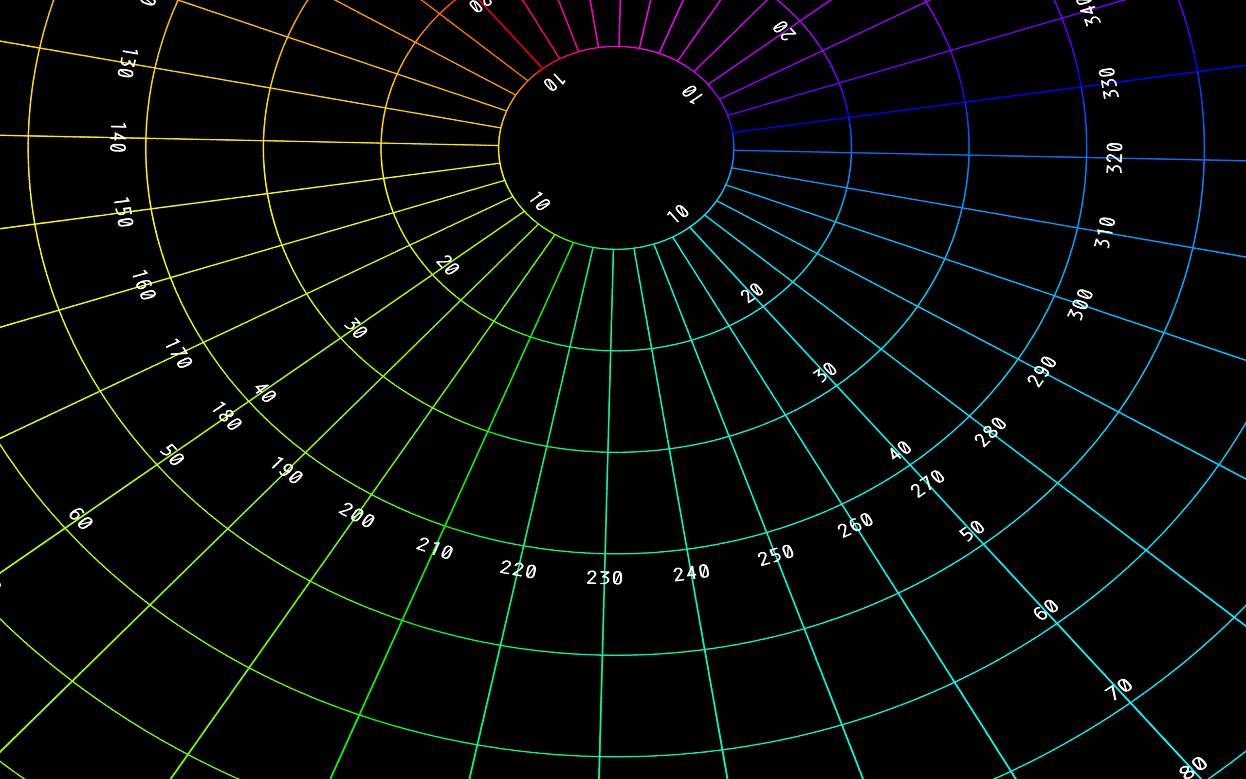
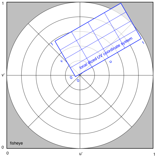
This is described separately and in more detail here, But in essence each 4K frame is split into 8 parts, one for each data projector and in the case of the DomeLab f50 projectors this is 2560x1600 pixels. The corners of the rectangle for the cutting are described by a simple CSV file of the form shown below, there are 8 such files, one per projector. posX;posY;rotation;extentX;extentY;pivotX;pivotY;c0x;c0y;c1x;c1y;c2x;c2y;c3x;c3y 0.6115;0.4378;-119.5600;0.5916;0.4276;0.2958;0.2138;0.5715;0.8006; 0.2796;0.2860;0.6515;0.0750;0.9434;0.5896;0.5715;0.8006 For this exercise only the last 8 numbers (c0x;c0y;c1x;c1y;c2x;c2y;c3x;c3y) will be considered, these are in normalised coordinates (0 ... 1) and may extend outside the fisheye area, that is, they can be less than 0 or greater than 1. A sample set of CSV cutting files for the 8 projectors is provided here: cutting.zip. Note that the resulting images contain more of the image than is absolutely necessary, this is to allow for slight changes in the projector positioning/angles and variations in the dome surface. As such these cuttings do not depend on the camera alignment. An example of the cutting region for the sample CSV file above is as follows, this example will be used subsequently to illustrate other points. Note that (0,0) is defined as the top left of the image. 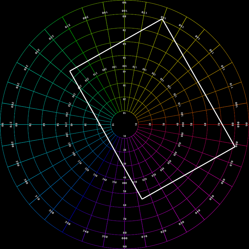 The final cut-out piece is shown below. 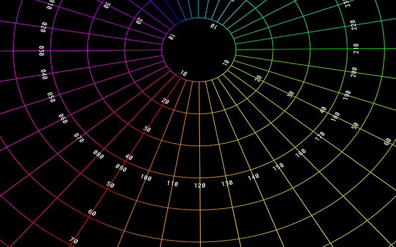
In the implementation developed for these tests a simple supersampling antialiasing is used for all image mappings, typically just a 2x2 supersampling. As with most image mappings the requirement is to find the best estimate of each pixel in the output image, that is, a reverse rather than forward mapping. Dome position and IG mapping
There is a mapping between the projector ID (name of the CSV files: 0 ... 7), the IG IP address and whether the left or right display is used (each IG drives two displays in monoscopic mode and 4 in stereoscopic mode). The mappings at the time of writing are as follows. 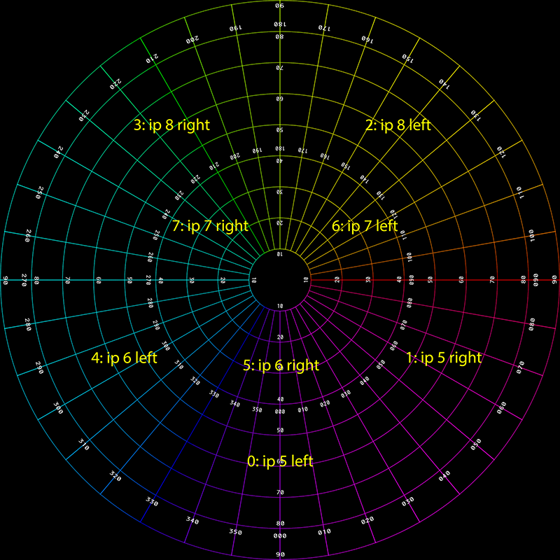
ffmpeg encoding
Once the fisheye movie is sliced into 8 streams, those image sequences need to be turned into 8 movie files. Each of these eventually gets installed onto the respective IG for playback from local disk. The current encoding for the movies in mpeg, generally performed using ffmpeg but other options are available. Command line encoding examples for the 7 channels is given below, note there are assumptions, first the slider software developed and described above creates each frame stream in folders 0 ... 7, and it currently only operates upon TGA image files. The input file string can be specified based upon other folder naming conventions and file types, a wide range are supported by ffmpeg but generally a lossless format should be used for this pipeline. ffmpeg -threads auto -r 30 -i "0/%05d.tga" -f vob -vcodec mpeg2video -b:v 50000k -minrate 50000k -maxrate 50000k -g 1 -bf 2 -an -trellis 2 "Display_0.m2v" ffmpeg -threads auto -r 30 -i "1/%05d.tga" -f vob -vcodec mpeg2video -b:v 50000k -minrate 50000k -maxrate 50000k -g 1 -bf 2 -an -trellis 2 "Display_1.m2v" ffmpeg -threads auto -r 30 -i "2/%05d.tga" -f vob -vcodec mpeg2video -b:v 50000k -minrate 50000k -maxrate 50000k -g 1 -bf 2 -an -trellis 2 "Display_2.m2v" ffmpeg -threads auto -r 30 -i "3/%05d.tga" -f vob -vcodec mpeg2video -b:v 50000k -minrate 50000k -maxrate 50000k -g 1 -bf 2 -an -trellis 2 "Display_3.m2v" ffmpeg -threads auto -r 30 -i "4/%05d.tga" -f vob -vcodec mpeg2video -b:v 50000k -minrate 50000k -maxrate 50000k -g 1 -bf 2 -an -trellis 2 "Display_4.m2v" ffmpeg -threads auto -r 30 -i "5/%05d.tga" -f vob -vcodec mpeg2video -b:v 50000k -minrate 50000k -maxrate 50000k -g 1 -bf 2 -an -trellis 2 "Display_5.m2v" ffmpeg -threads auto -r 30 -i "6/%05d.tga" -f vob -vcodec mpeg2video -b:v 50000k -minrate 50000k -maxrate 50000k -g 1 -bf 2 -an -trellis 2 "Display_6.m2v" ffmpeg -threads auto -r 30 -i "7/%05d.tga" -f vob -vcodec mpeg2video -b:v 50000k -minrate 50000k -maxrate 50000k -g 1 -bf 2 -an -trellis 2 "Display_7.m2v" The output names above (Display_0.m2v, Display_1.m2v ... etc) are conventions required by the current Watchout configuration. Audio channel mapping
The audio channels should be combined in a single 6 channel WAV file with the following channel assignments. For plain stereo audio the WAV file channel 1 is left and channel 2 is right. Note that these channel assignment can be remapped in Watchout if necessary.
Geometry correction (warping)
The geometry correction, arising from the projection of a rectangular perspective projected image onto a non-planar surface, is implemented by a mesh. The resolution of the mesh is typically not per pixel but generally tens of pixels across. Each node of the mesh is defined by a position (x,y) and a texture coordinate (u,v). There are two ways of encoding the warping required. The first is to use a regular grid in (x,y) and vary the (u,v) coordinates, the other is to use a regular (u,v) array and vary the (x,y) position coordinates. (Actually one could use a combination of these but that is rarely done.) An example of the first few lines of the CSV files for a warp file encoding by (u,v) is given below for a 64x40 mesh. x;y;u;v;column;row 0.0000;0.0000;0.1986;0.0584;0;0 0.0169;0.0000;0.2076;0.0647;1;0 0.0339;0.0000;0.2162;0.0711;2;0 0.0508;0.0000;0.2245;0.0774;3;0 0.0678;0.0000;0.2328;0.0838;4;0 0.0847;0.0000;0.2412;0.0899;5;0 : : : 0.9661;0.0000;0.7566;0.0712;57;0 0.9831;0.0000;0.7655;0.0648;58;0 1.0000;0.0000;0.7748;0.0584;59;0 0.0000;0.0256;0.1957;0.0757;0;1 0.0169;0.0256;0.2048;0.0821;1;1 0.0339;0.0256;0.2132;0.0887;2;1 : : : 0.9661;1.0000;0.9155;0.7727;57;39 0.9831;1.0000;0.9282;0.7614;58;39 1.0000;1.0000;0.9407;0.7508;59;39 A sample set of warp CSV files of each type are provided here: warping_uv.zip and warping_xy.zip. The following is the (u,v) warp mesh (regular x,y) with the u components encoded on the red channel and v encoded on the green channel. It is a 60x40 cell mesh, the x and y values would range of 0 ... 1. 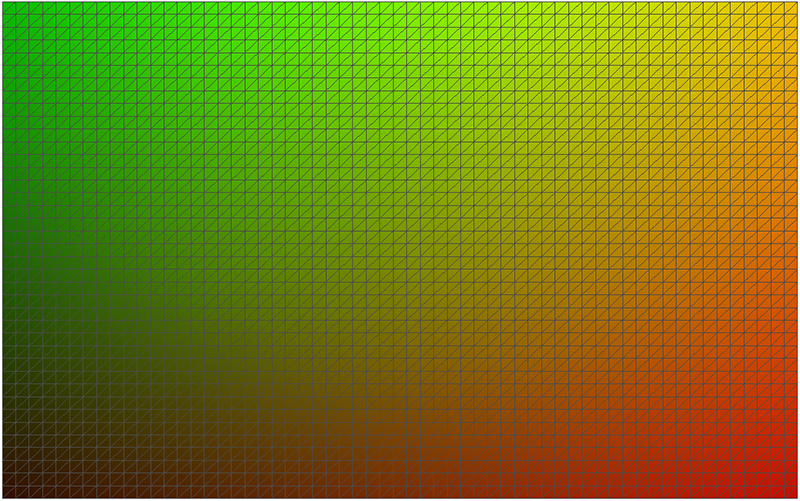
The following is the x,y warp mesh (regular u,v) with the same (u,v) encoding as figure 4. It is a 60x40 cell mesh, the u and v values would range of 0 ... 1. While it may be difficult to imagine how these give the same results, this can shown by realising the rectangle in figure 4 can be scaled and found in a rectangular region of figure 5, and that rectangular region corresponds to (x,y) coordinates each ranging from 0 to 1 in figure 5. 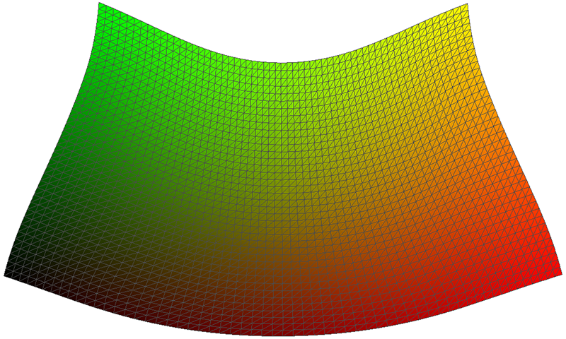
The warped version of the cutting extracted in figure 1 and figure 2 is given below, this uses the (u,v) mesh but the result would be the same with the (x,y) mesh. Note that the coordinate for x,y position are 0 ... 1 on both axes, rather than the more usual -1 ... 1 vertically and -aspect ... aspect horizontally, but this is a simple translation/scaling transformation. 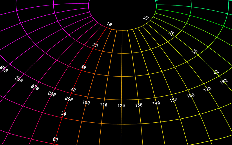
These are both identical in concept to the warp mesh files the author uses for lots of things: warpplayer, VLC, Quartz Composer, Vuo ... and can easily be turned into obj files for Unity, and of course other formats as well. Blending
Blending is applied as a multiplicative factor for every pixel in the geometry corrected image. This is supplied as an image file (png), a sample set is provided here: blending.zip. Remember this and the warping mesh will potentially change after every calibration process. A sample blend file is given below for the cutting extracted in figure 1 and figure 2. This is more complicated than most since it is near the pole of the dome where three projector images overlap. 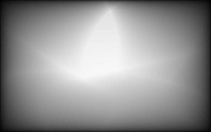
The blend applied to the cutting extracted in figure 1 and figure 2. This is a multiplicative factor applied on a pixel by pixel basis. 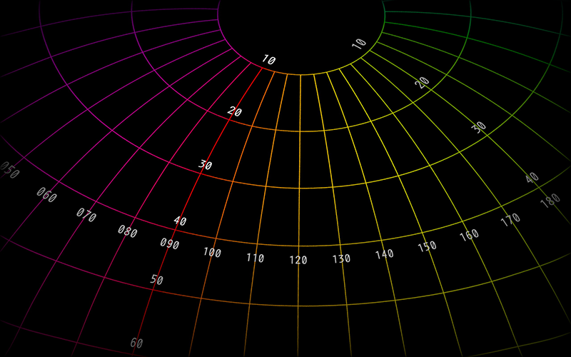 Unity
The following describes one possible way of implementing the warping and blending required in the Unity game engine. While the solution example presented here will use a single workstation with 8 graphics pipes (one for each data projector), the solution at least from the perspective of the graphics is no different for a cluster setup using the cluster version of Unity. The first requirement is that a fisheye view of world is created in Unity. This is achieved by creating a 4 camera rig, rendering each camera to an off-screen texture, applying each of these textures to 4 special meshes whose texture coordinates have been designed to form the fisheye. Finally this fisheye is viewed with a fifth camera which creates a 4Kx4K fisheye as a render texture. This process has been described elsewhere, for example: here or here. 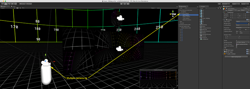
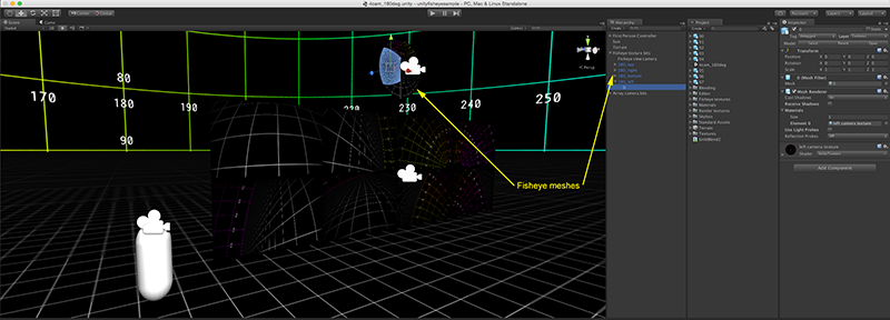
This fisheye is now applied 8 times to meshes encapsulating the required warping for each of the projected images. As discussed this is defined by the csv files from the calibration tool, they only need to be adjusted so that the uv coordinates relate to the fisheye rather than the cropped/extracted section. An example of the 8 obj files describing the meshes for Unity is supplied here: warpasobj.zip. Note that these potentially need to be re-read into Unity whenever a calibration is performed. 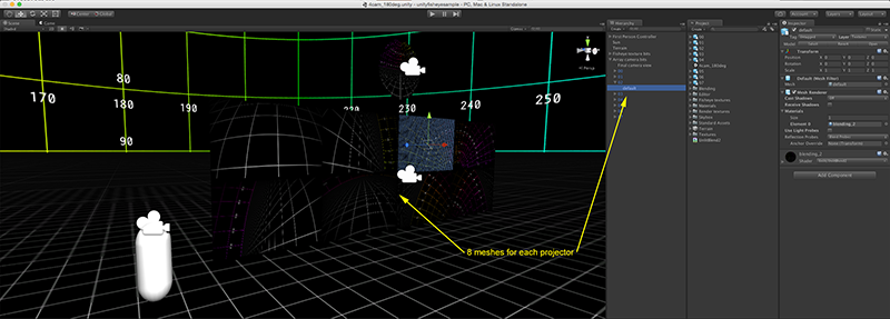
The blending is applied directly using a unlit multiplicative shader and using the blend images directly from the calibration software. The shader is given here: UnlitBlend2.shader. 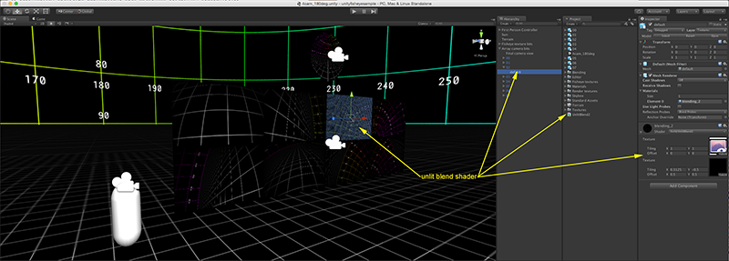
Finally, the 8 images are viewed with a final camera. The 8 textured panels need to be laid out to match identically with how the graphics pipes on the graphics card are connected to the projectors. In a single computer case this would normally be as a mosaic in Windows such that when Unity is launched full screen it uses the whole real-estate each section of which is in turn mapped to each projector. Note also that all these "non-scene" objects are normally placed on a separate layer such they are not visible from the scene cameras and also do not inherit any lighting. 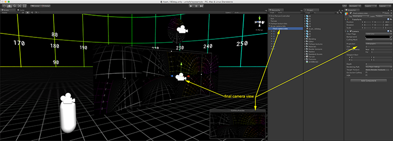
Appendix 1: Test pattern
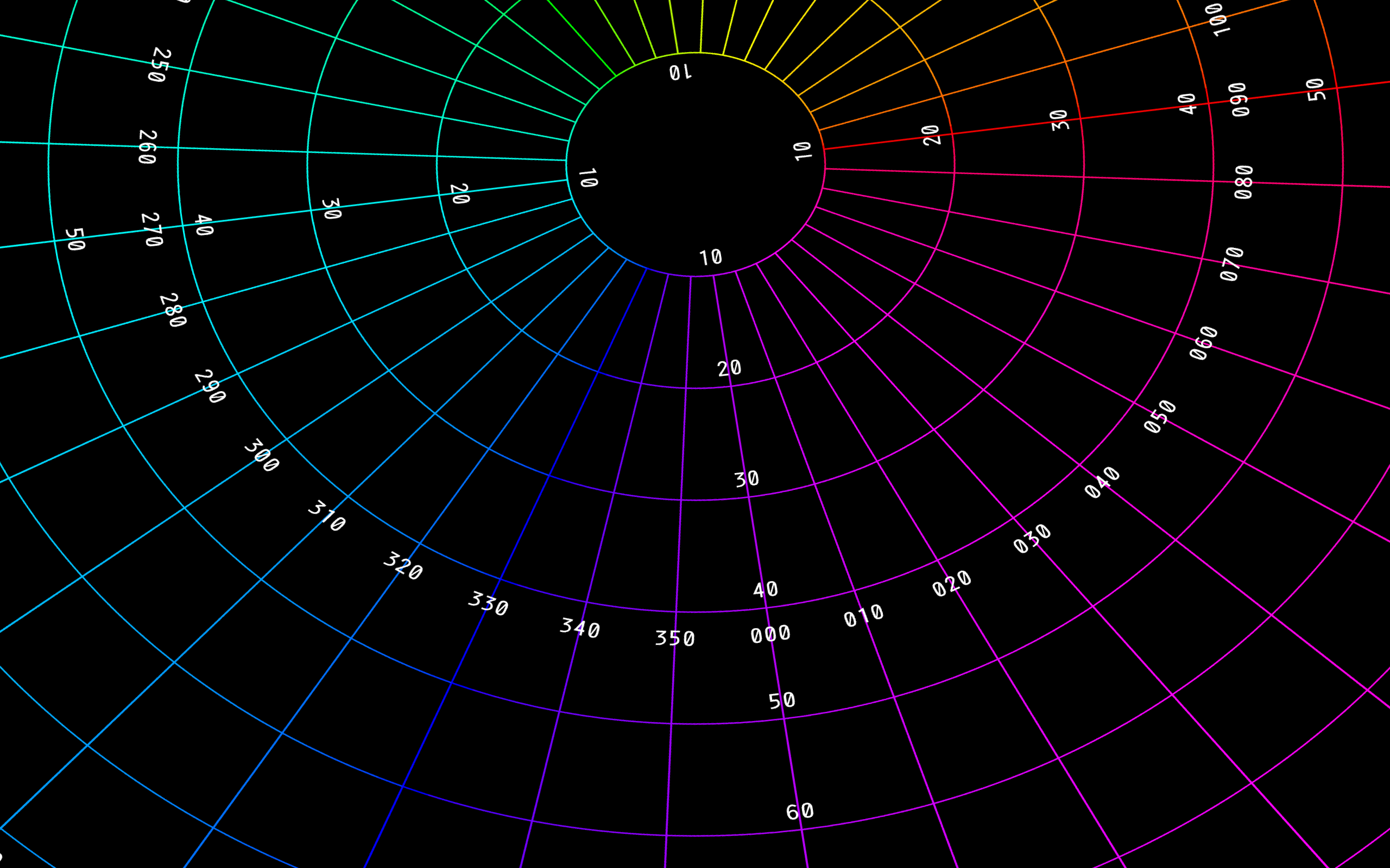
Test pattern used here is provided as a 4Kx4K image with longitude and latitude markings every 10 degrees: polar.png. 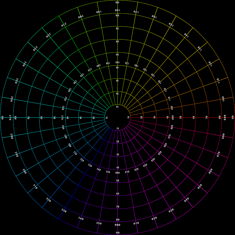
Appendix 2: Complete set
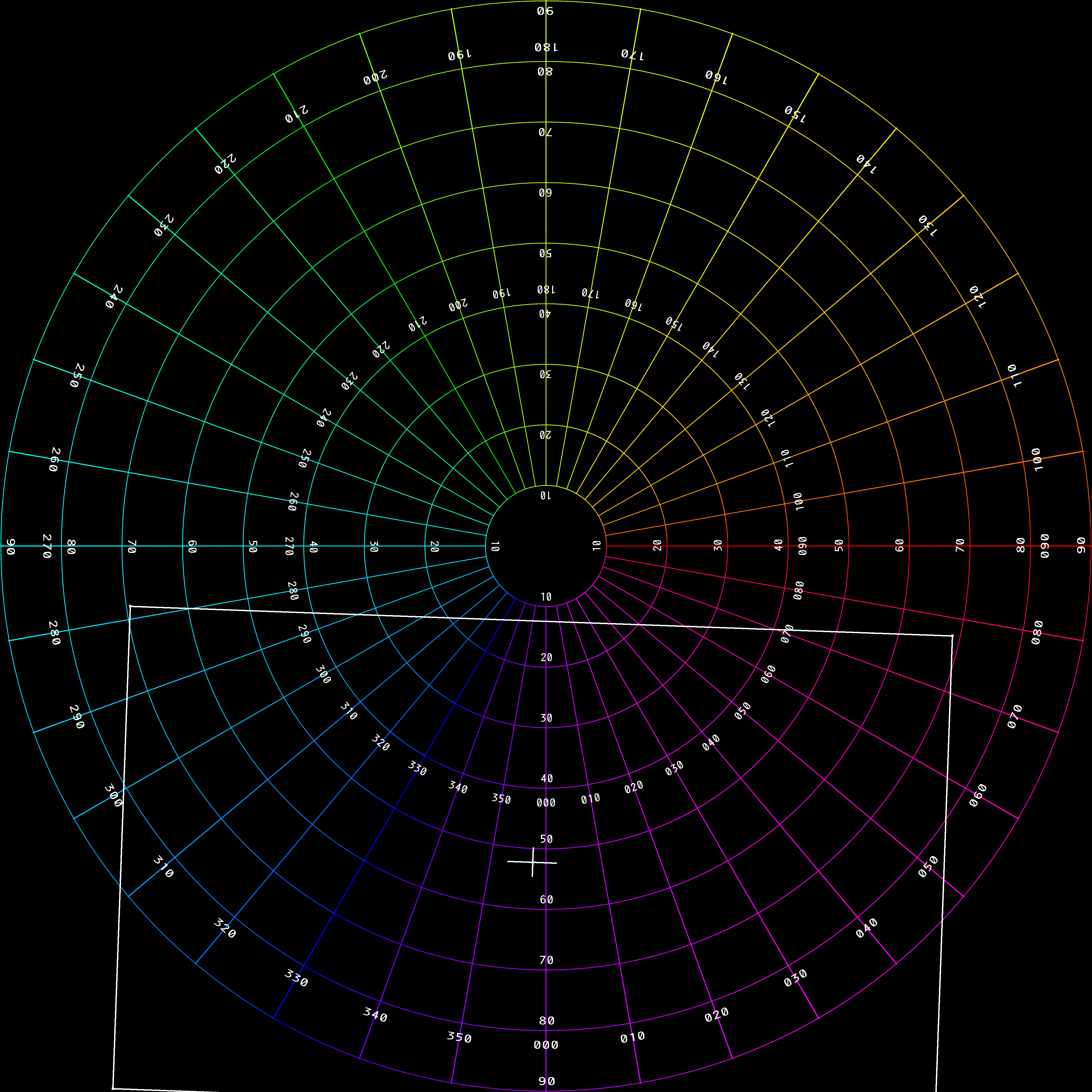
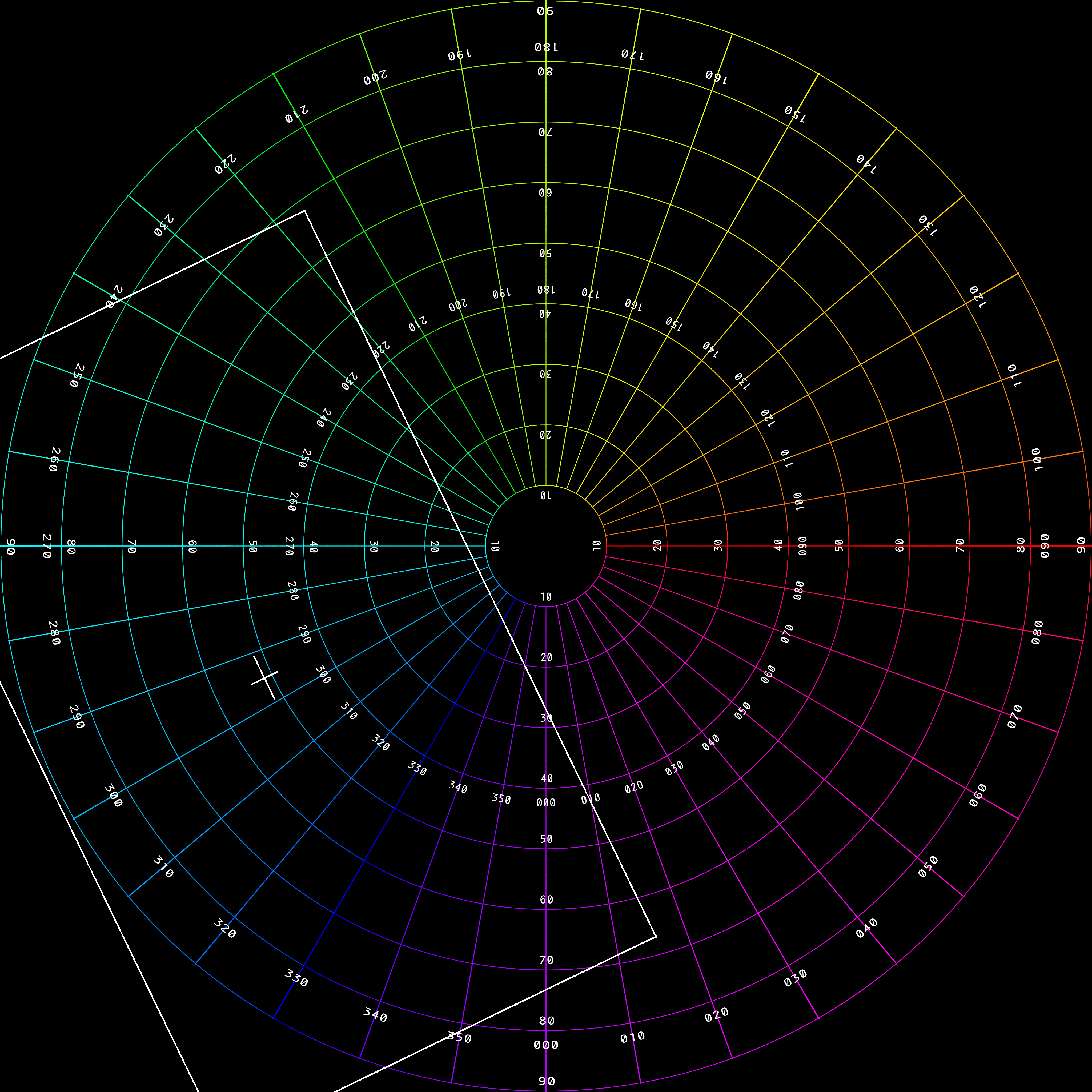
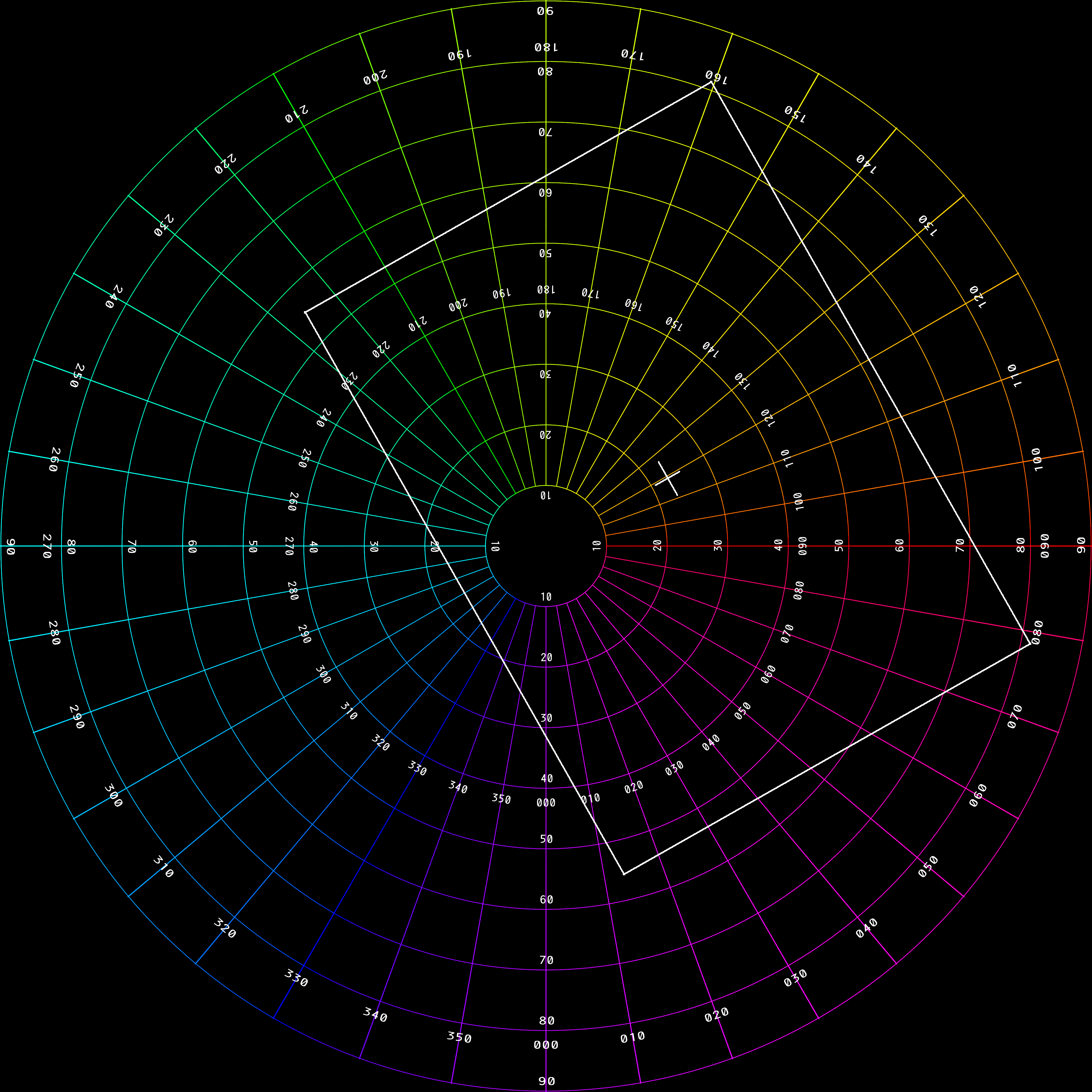
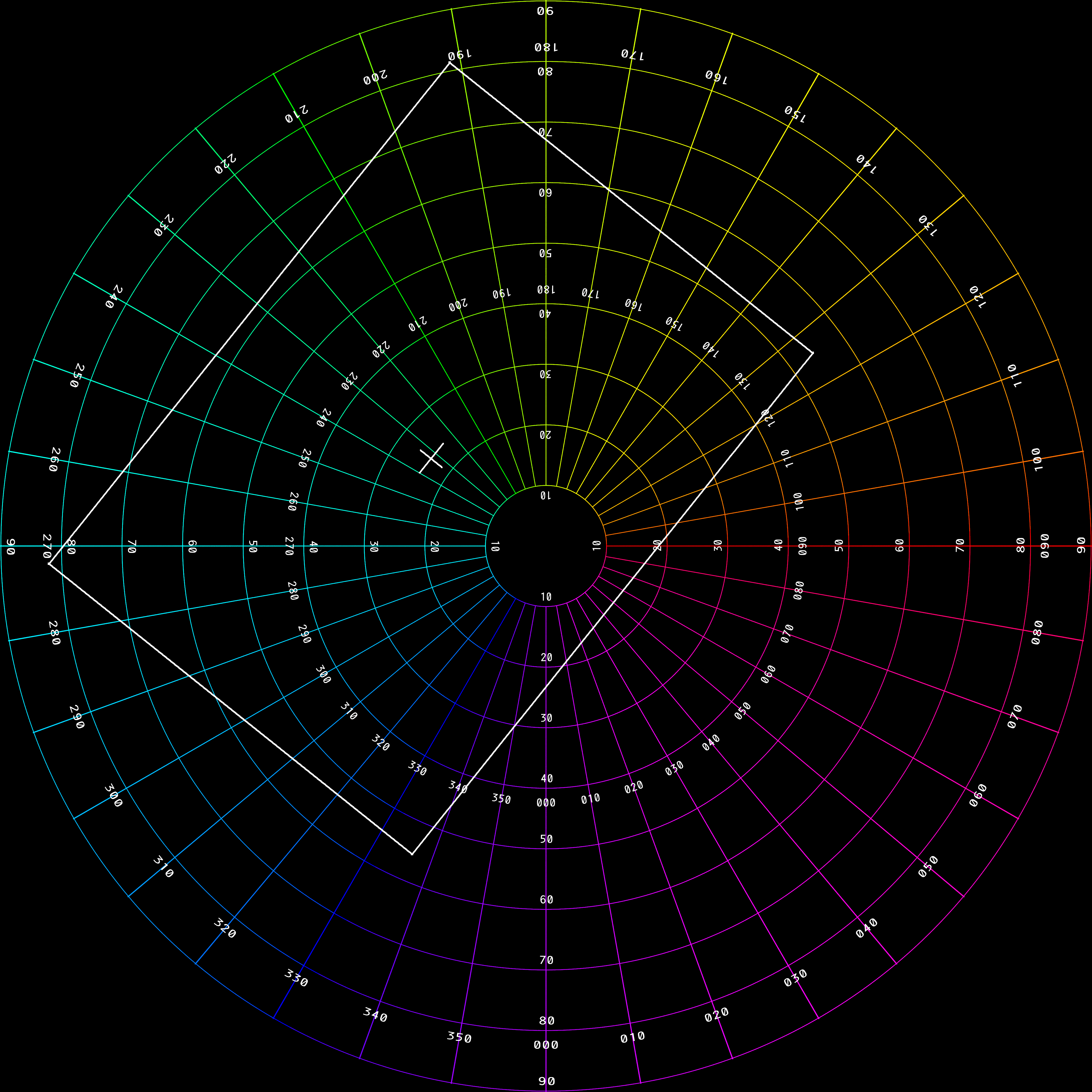
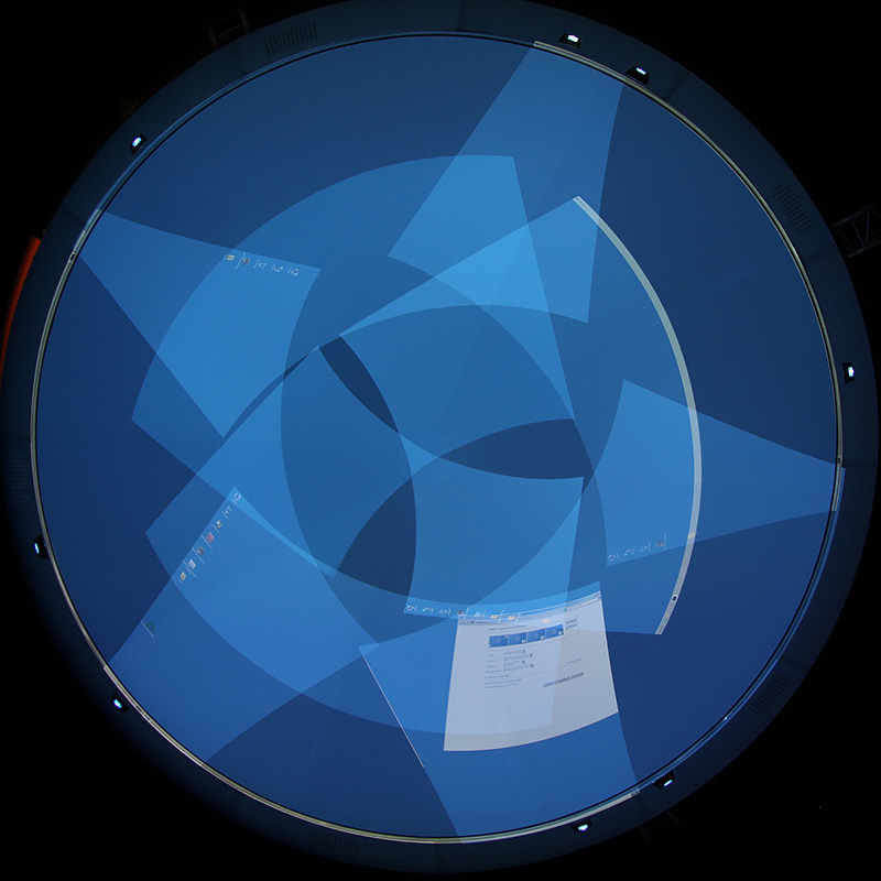
Another method of extracting the appropriate rectangle from the CSV file example shown at the top of this document is to use the first 5 parameters. That is, the X and Y extent defines a rectangle centered at the origin and in units of a (0,1) bounded fisheye. This rectangle is then rotated by the rotation angle indicated, in degrees. And lastly translated to position indicated as (posx,posy), again in unit bounded fisheye coordinates. The complete set of extracted rectangles and their position in the fisheye circle are shown below, the white rectangle is the same irrespective if the geometric transformation or bounding coordinates CSV data is used. The central cross hair shows the value of posx,posy.
Appendix 3: Projector overlap
|
