Spatial errors in stereoscopic displays(In the absence of head tracking)Written by Paul BourkeMarch 2017
In collaboration with Andrew Woods and Joshua Hollick.
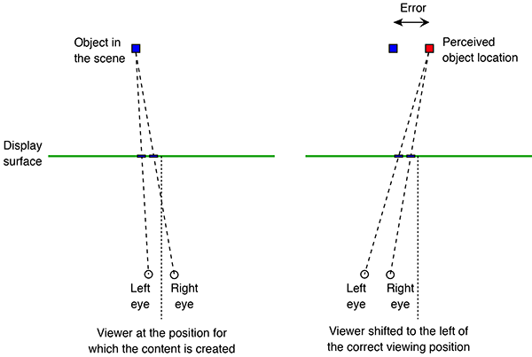
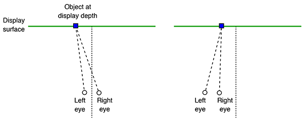
Stereoscopic displays present the viewer with a sense of depth, that is, objects presented on the display are perceived to appear in front of (negative parallax) or behind the display surface (positive parallax). However, in order for the depth perception to be correct, there needs to be a match between the optics of the viewer and the optics of either the stereoscopic recording system (camera and lens) or the computer rendering configuration (virtual camera and lens). So, for example, the left and right eye cameras need to match the viewer's eye separation. The relationship of the viewer's position to the display surface needs to match the position and field of view of the camera lens, this includes a match between the view frustum from the viewer position to the corners/edges of the display. This rigour is rarely satisfied. Not all audience members watching a stereoscopic movie can be collocated in the same position. Even if some care is taken to record the stereoscopic content correctly for one viewer, the viewing conditions change for different size displays (theatre vs home television for example). Satisfying different screen sizes alone would require a multiplicity of different recordings and associated post production exercises. The reality is that every stereoscopic experience, even if recorded correctly (which is rarely the case), presents a distorted sense of space except possibly for a single person. The cause of this distortion is most easily appreciated by considering two viewer positions (figure 1), the projection of an object onto the display for each of these positions should be different and yet for precomputed or recorded content it clearly cannot be since it was only captured or rendered from a single position.
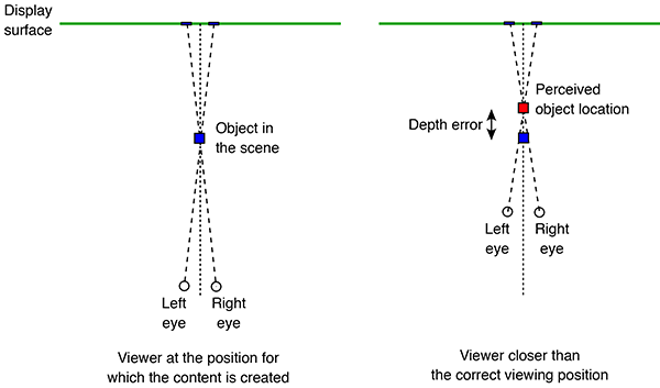
The effects of the distortion due to a non-stationary viewer are clear to anyone who has moved about when watching pre-rendered stereoscopic content, moving towards or away from the display results in a compression or stretching of depth respectively (figure 1 and 2). Moving to the left or right results in a sheering of depth across the display. The same effect occurs vertically, for example, for viewer's of different heights. Another way to think about this is to realise that if an object is, for example, located half way between the viewer and the display surface, it is always located half way despite the viewer moving towards or away from the display. Fortunately, if a viewer stays stationary (eg: seated) then we seem to be relatively insensitive to these spatial distortions, or at least rapidly adapt.
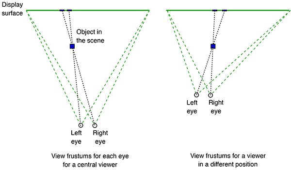
In virtual reality (VR) applications where the viewer does wish to move around, for example, to look at objects from different viewpoints, the solution is well established. Since the content is being generated in real time it is possible to track the viewer and configure the virtual camera to create the correct view frustums for each eye (figure 3). Indeed this tracking might be considered key to calling something a VR experience since it is attempting to reproduce what is occurring naturally in reality.
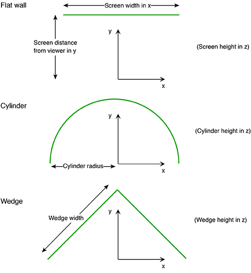
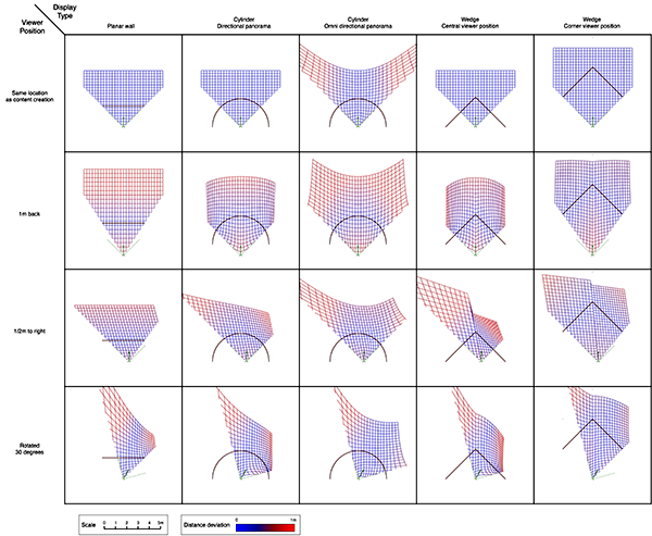
For precomputed content there will in general always be spatial distortion, this will arise for a single viewer not located in the position for which the stereoscopic content is created, or if there are multiple viewer's since all but one can be in the correct location. It can be noted here that the degree of spatial distortion increases with the increased distance the viewer is from the so-called "sweet spot", the position from which the content was recorded or rendered. This is relative to the scale of the display, so a large display can support more viewer's within some tolerated maximum spatial error. In what follows a method will be described for estimating the spatial error for a number of stereoscopic display geometries. Three types will be presented, a single flat display, a wedge (two flat displays at right angles to each other) and an 180 degree cylindrical display (figure 4). For all displays four situations will be considered, the viewer at the sweet spot, the viewer 1m further back, 1/2m to the right, and finally at the sweet spot but looking 30 degrees to the right. For the wedge two sweet spot locations in common usage will be examined, one with the sweet spot in the center and the other at the opposite corner of the box for which the wedge defines 2 sides.
In the cylindrical case, there are two types of content, directional and omnidirectional stereoscopic panoramas. Directional stereoscopic panoramas are only designed for the viewer to be looking forward, the display real-estate towards the edges of the cylinder is there only to support peripheral vision. Omnidirectional stereoscopic panoramas intentionally provide an increasingly incorrect stereoscopic view towards one peripheral vision, but has the advantage of the viewer being able to look around with a correct stereoscopic stimuli in the center of their field of view. Planar wallDimensions: width 3.75m, height 2m, distance from viewer 1.875m.
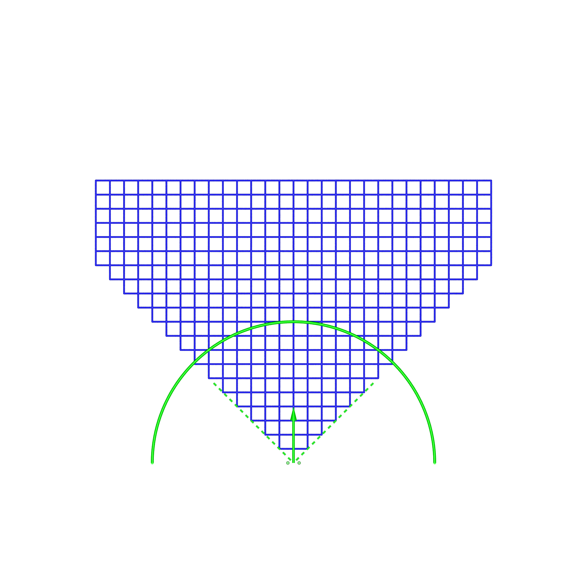
In the analysis presented here the viewer's field of view is limited to 90 degrees (green wedge). This eliminates numerical issues for some cases, provides a consistent scaling between the display cases, allows the range of distortions to have a constant scale. The justification is that since the viewer is wearing some sort of eye-wear (glasses) they typically have a limited field of view for the stereoscopic effect. While thin rimmed glasses allows the viewer a view outside the rim of the glasses, one does not perceive depth perception in that area due to it being outside the rim of the glasses or due to one eye being blocked by the viewer's nose. The simulation software that creates the following diagrams has a parametrised description of each display. The dimensions of each are set as similar as possible in order to facilitate comparison. The algorithm functions as follows:
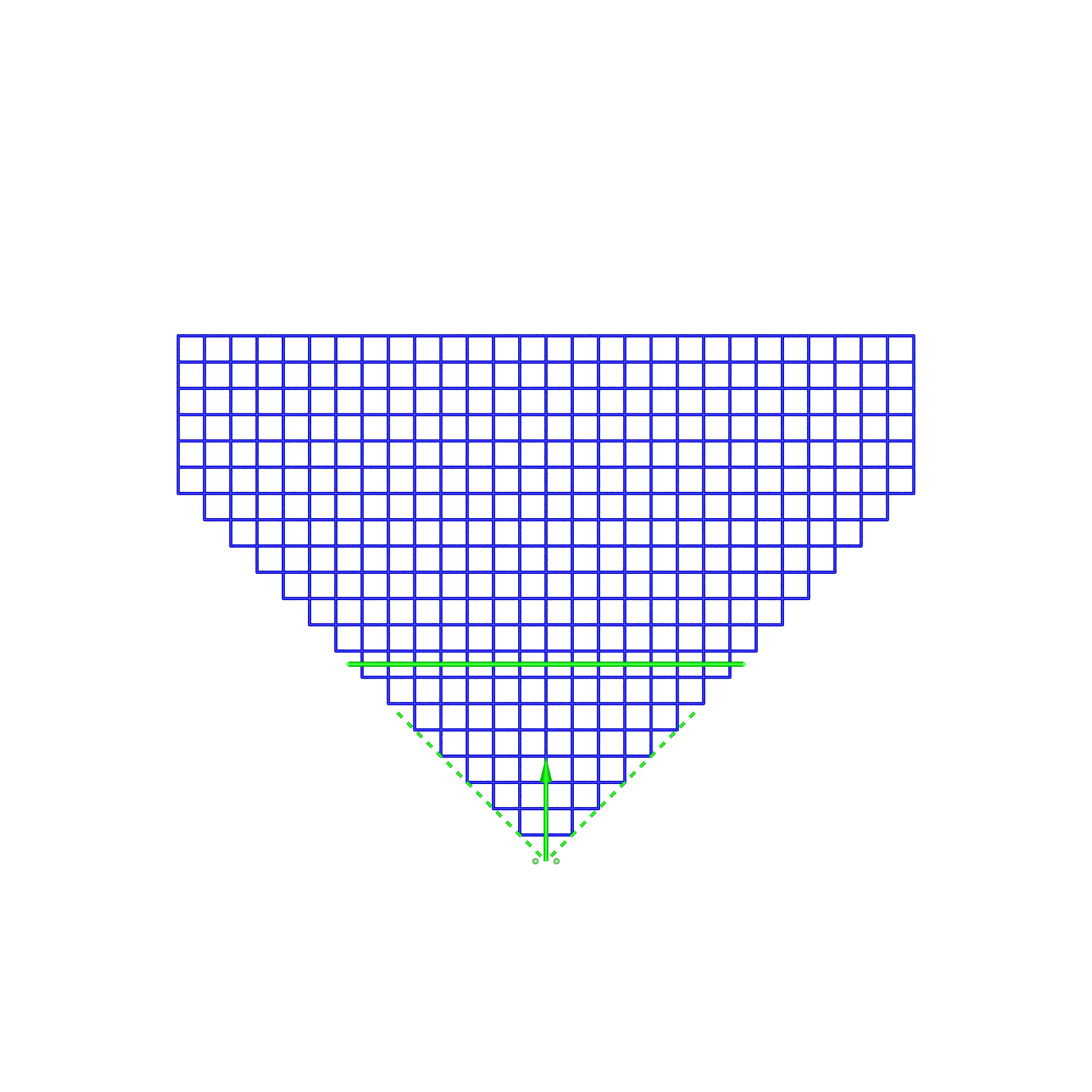
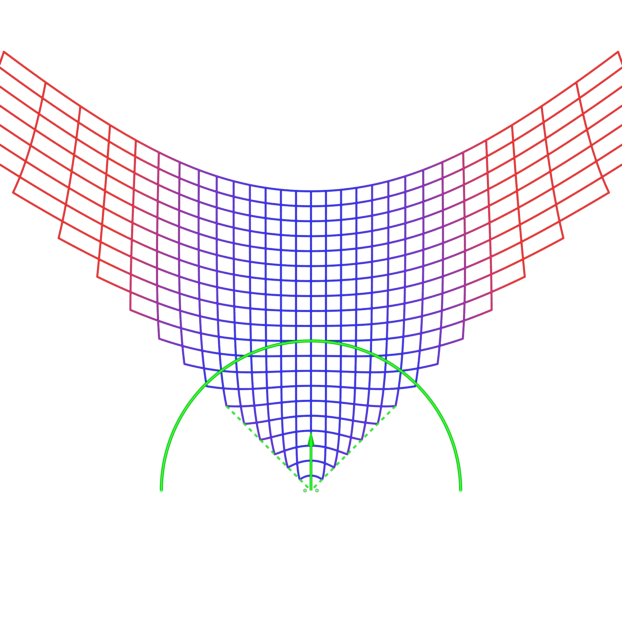
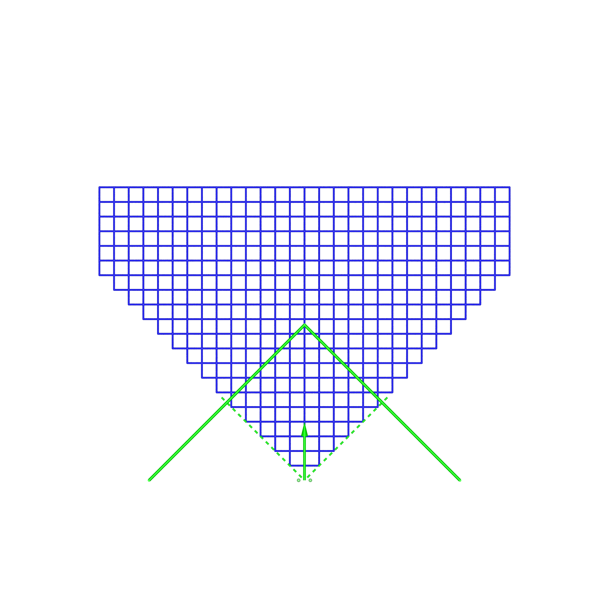
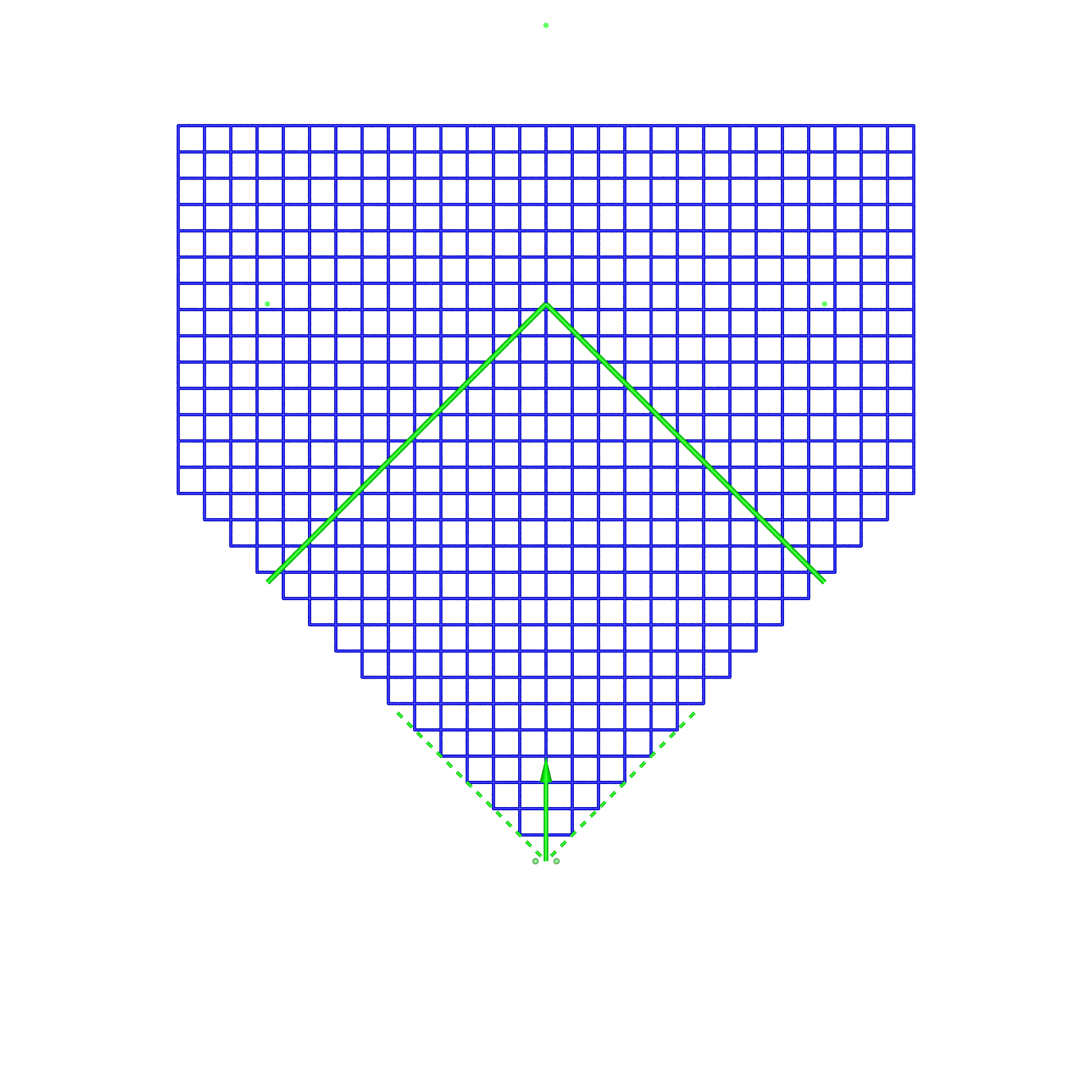
In the simulation and following diagrams the screen, position of each eye and horizontal field of view are shown in green. All views are in plan, the regular grid is on the x-y plane, z-axis is up. The viewer is at the origin and centered on the display vertically. A similar analysis could be performed vertically, or even volumetrically, but the salient features can be understood with the 2D grid considered here.
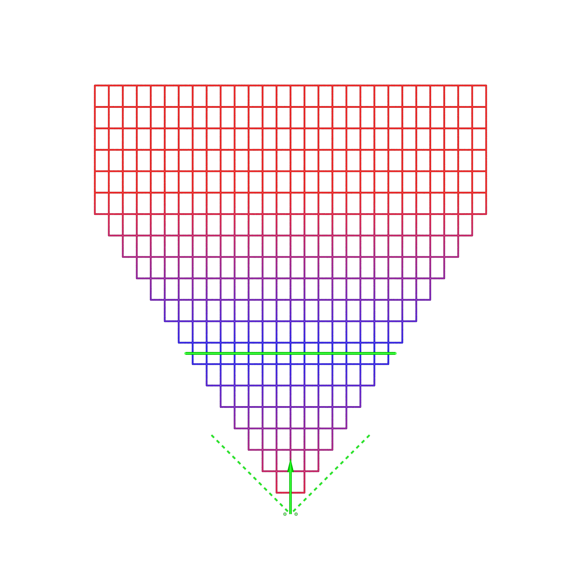
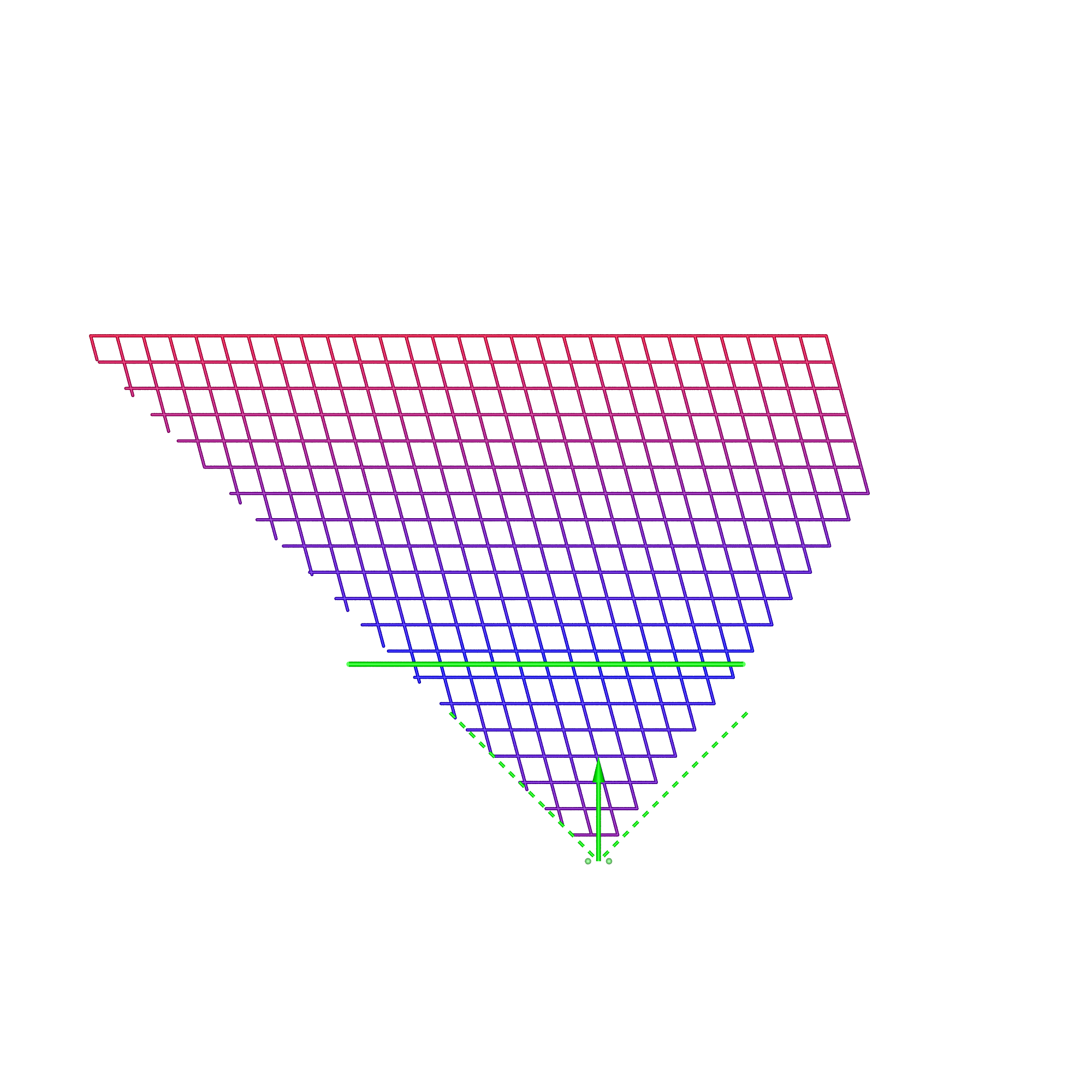
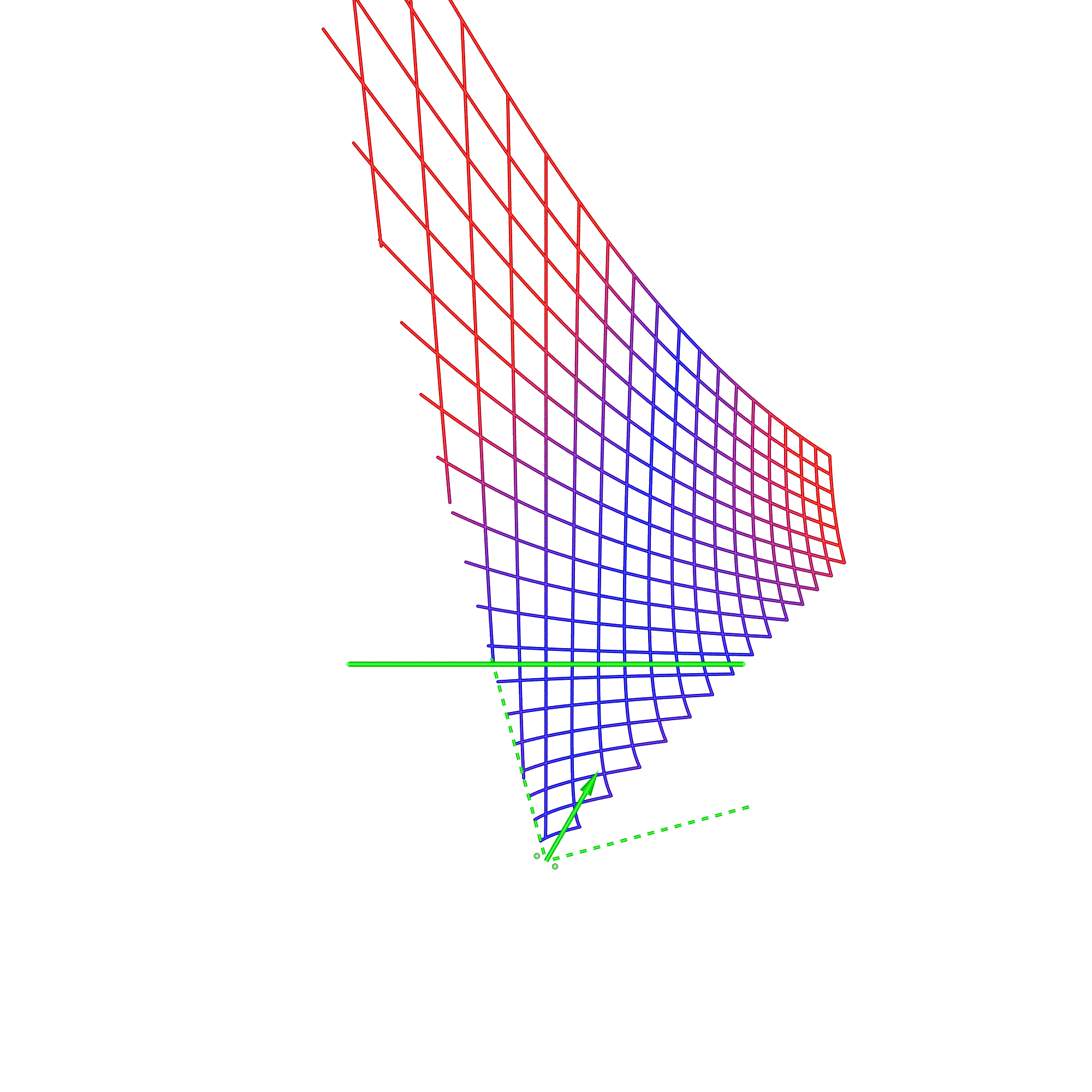
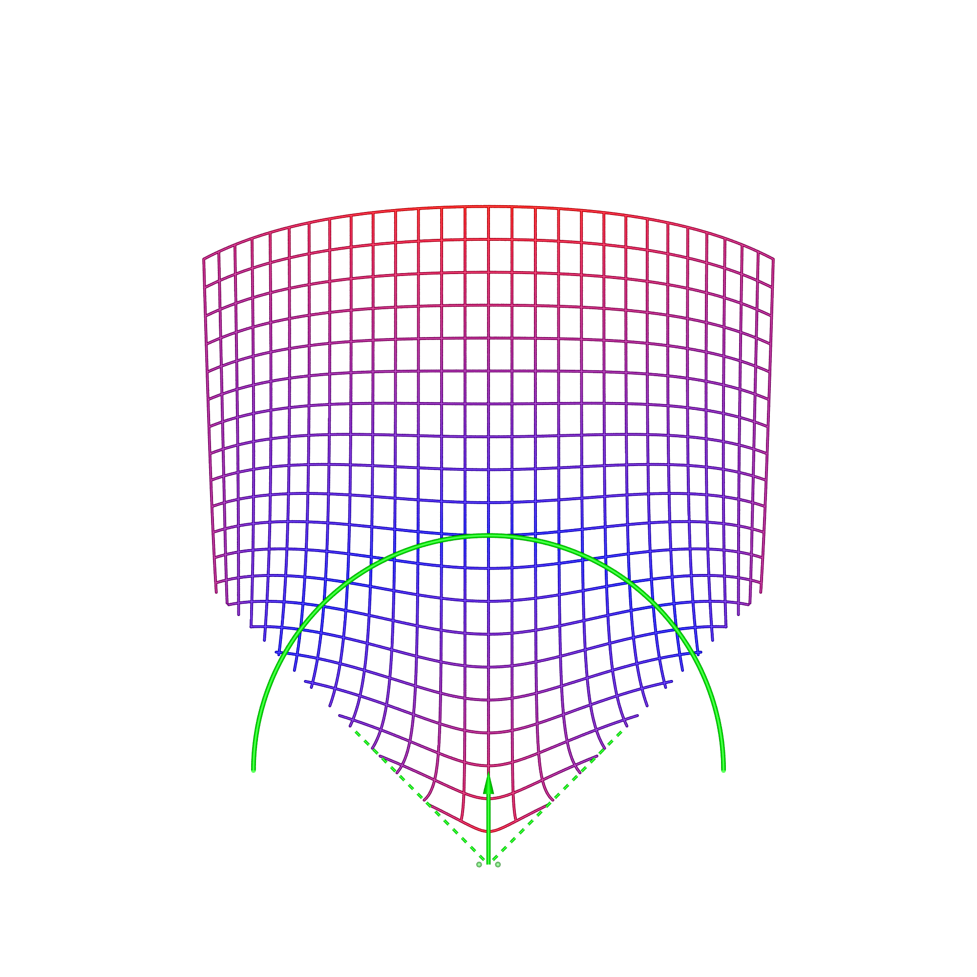
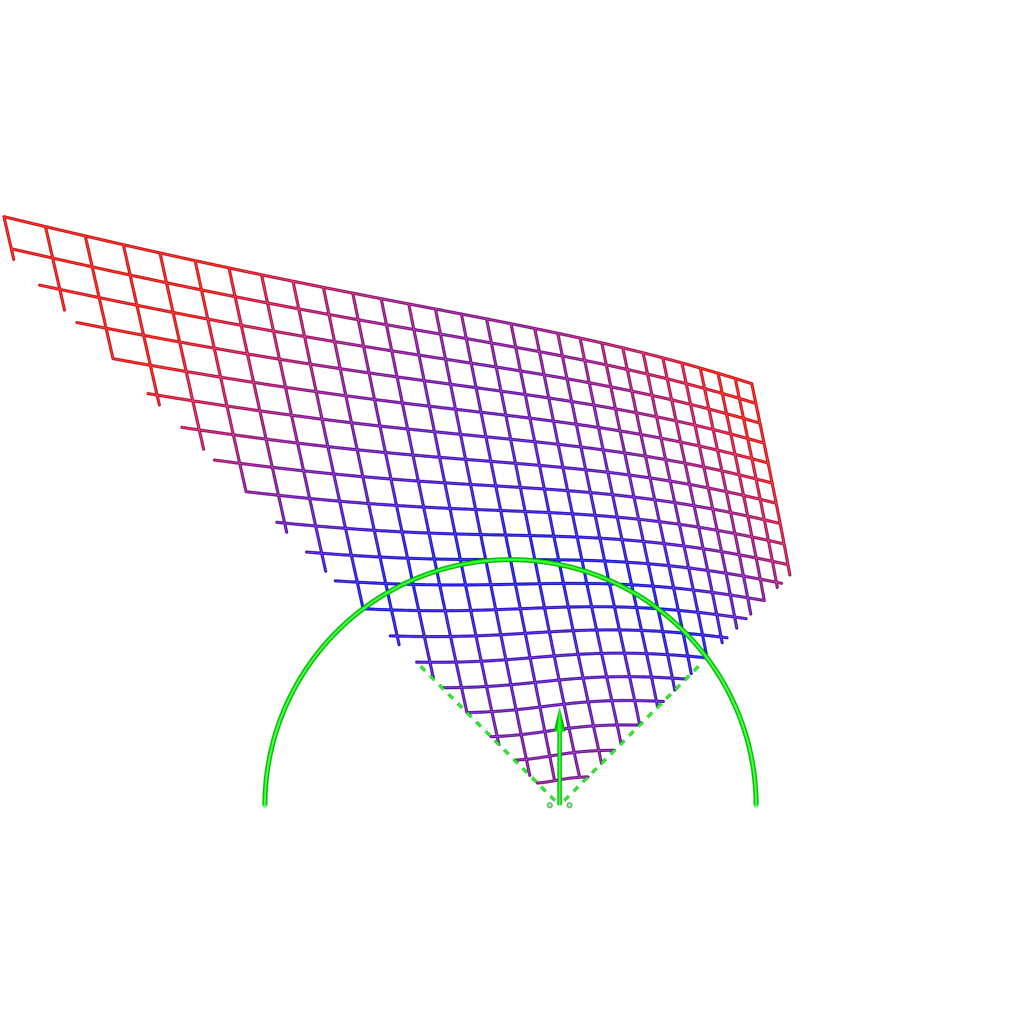
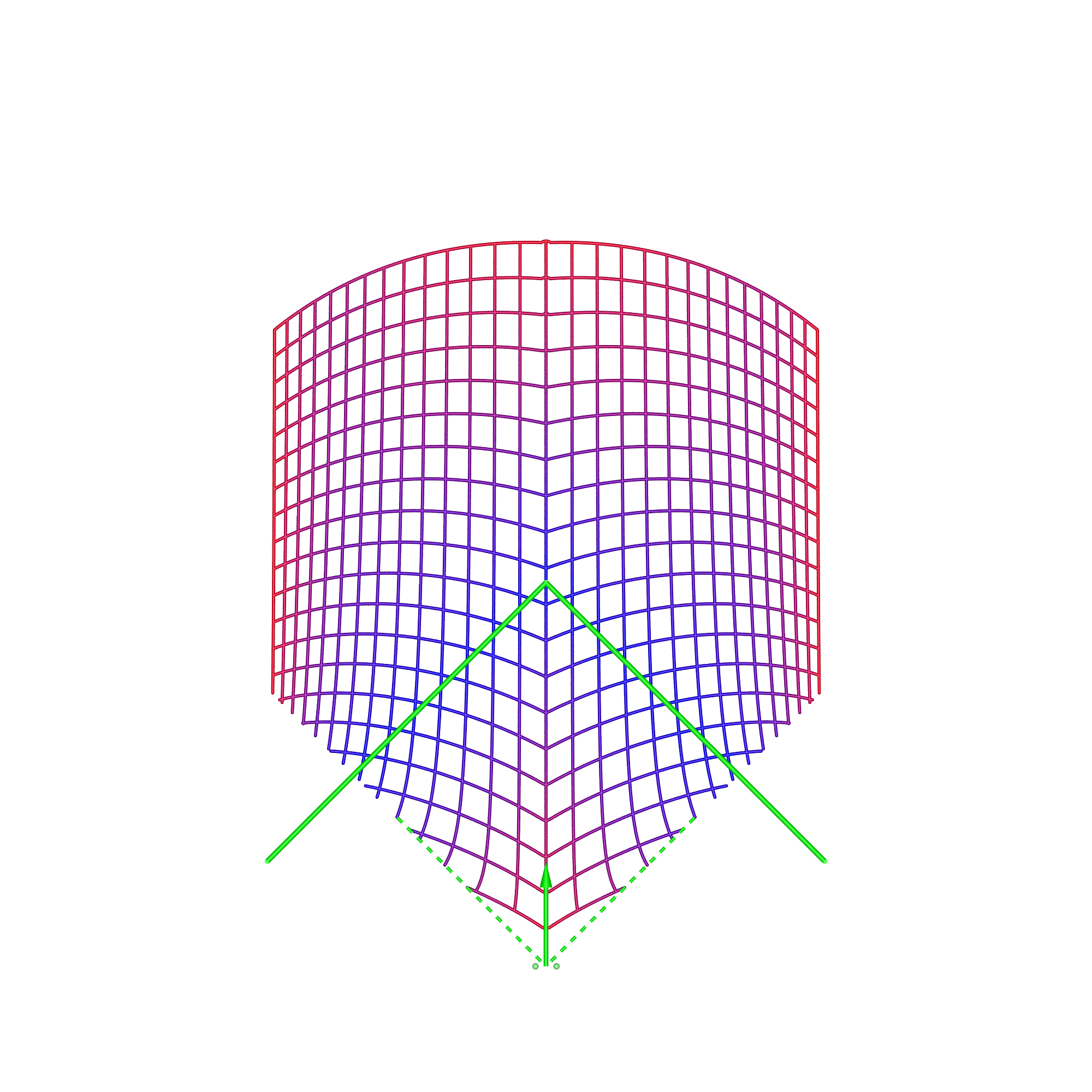
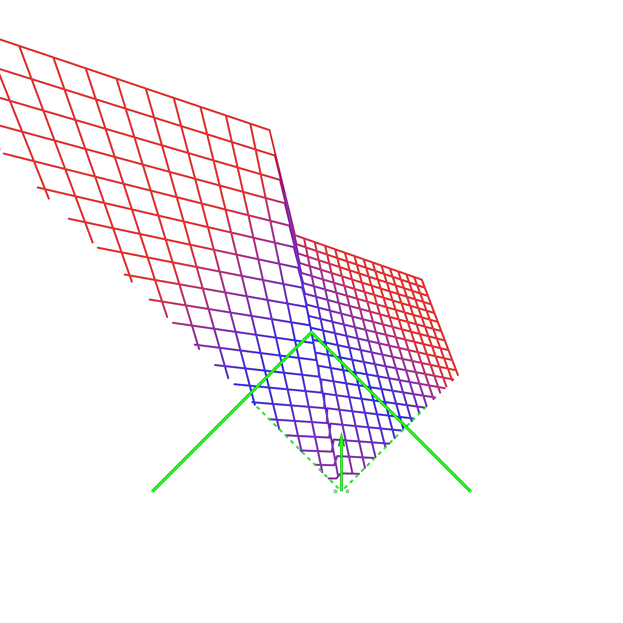
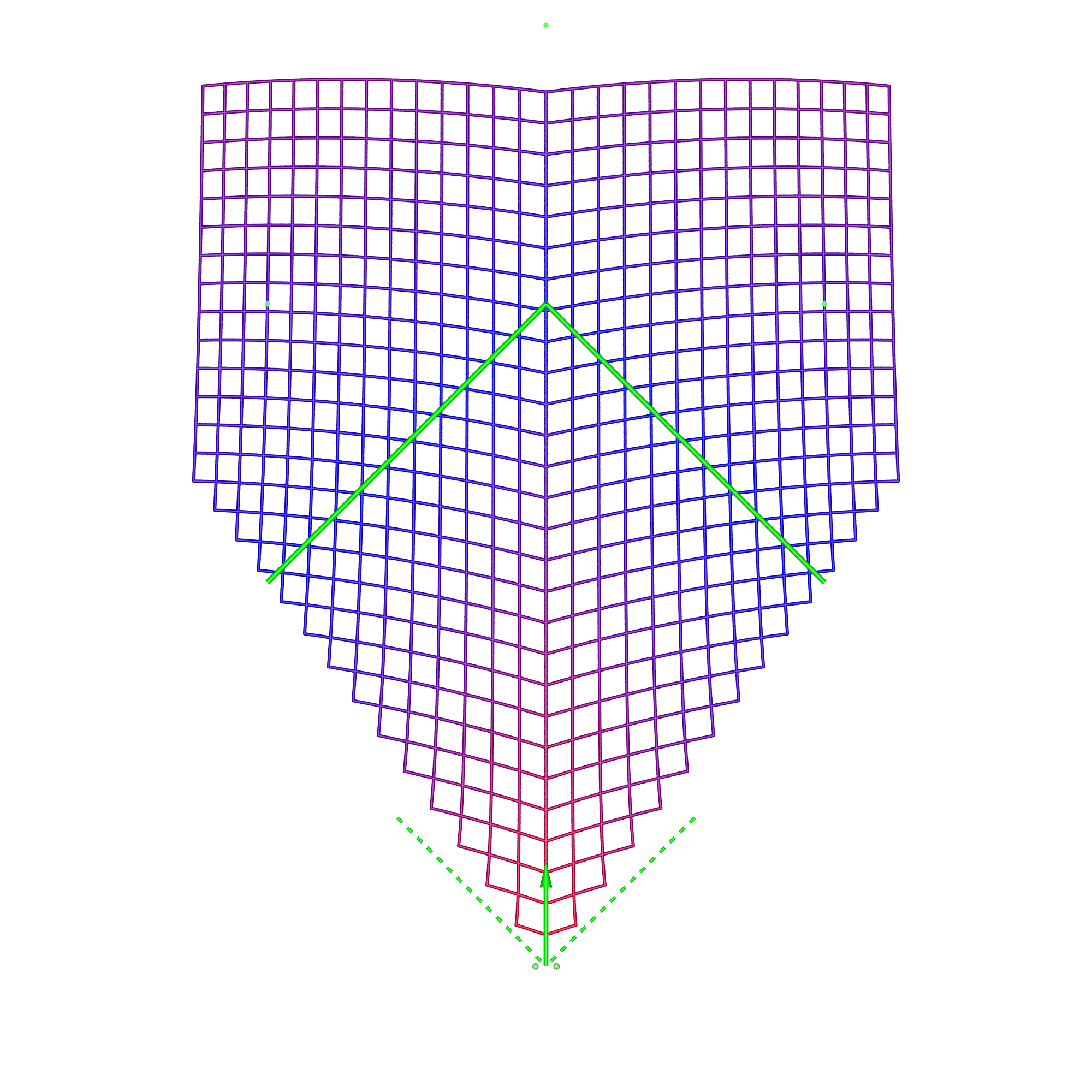
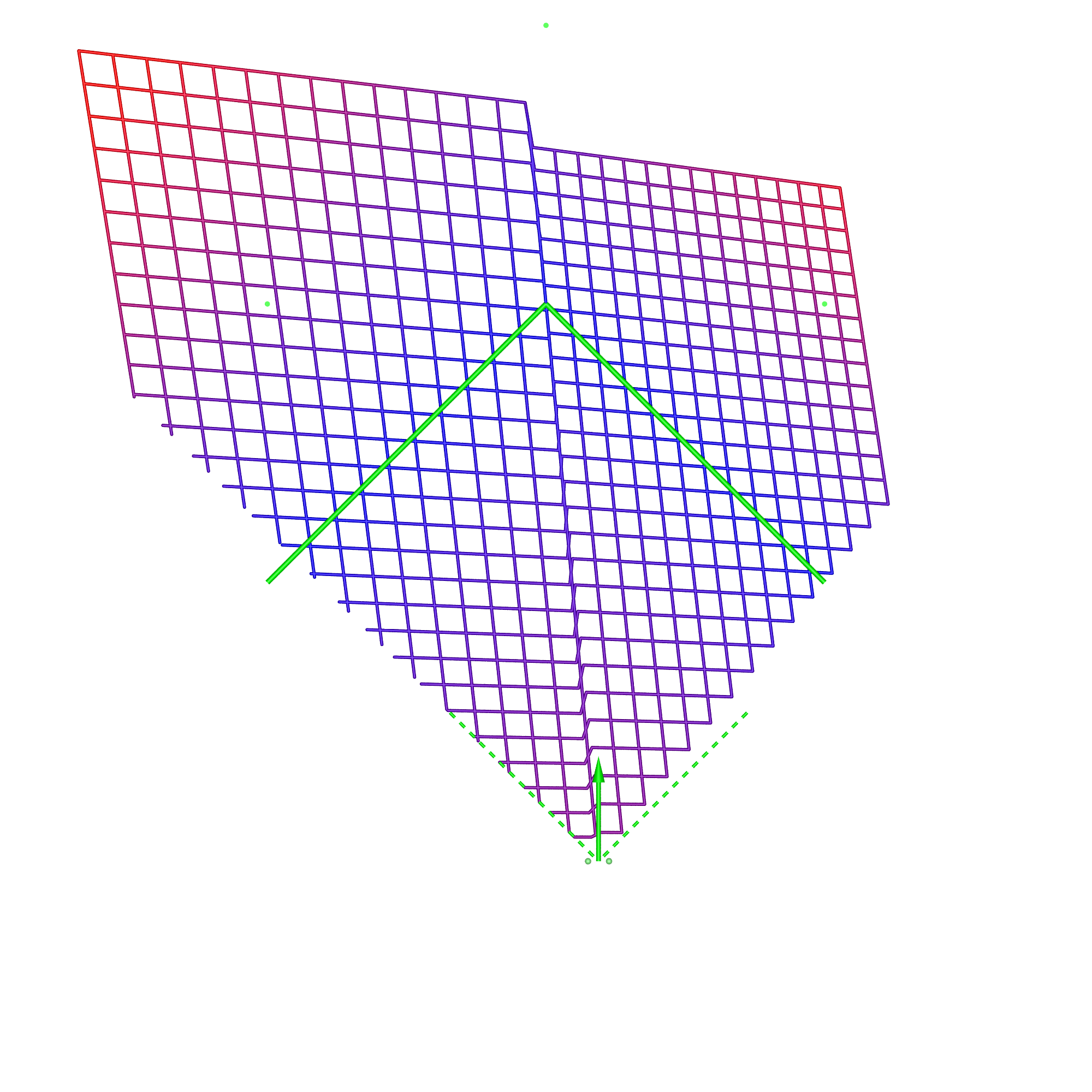
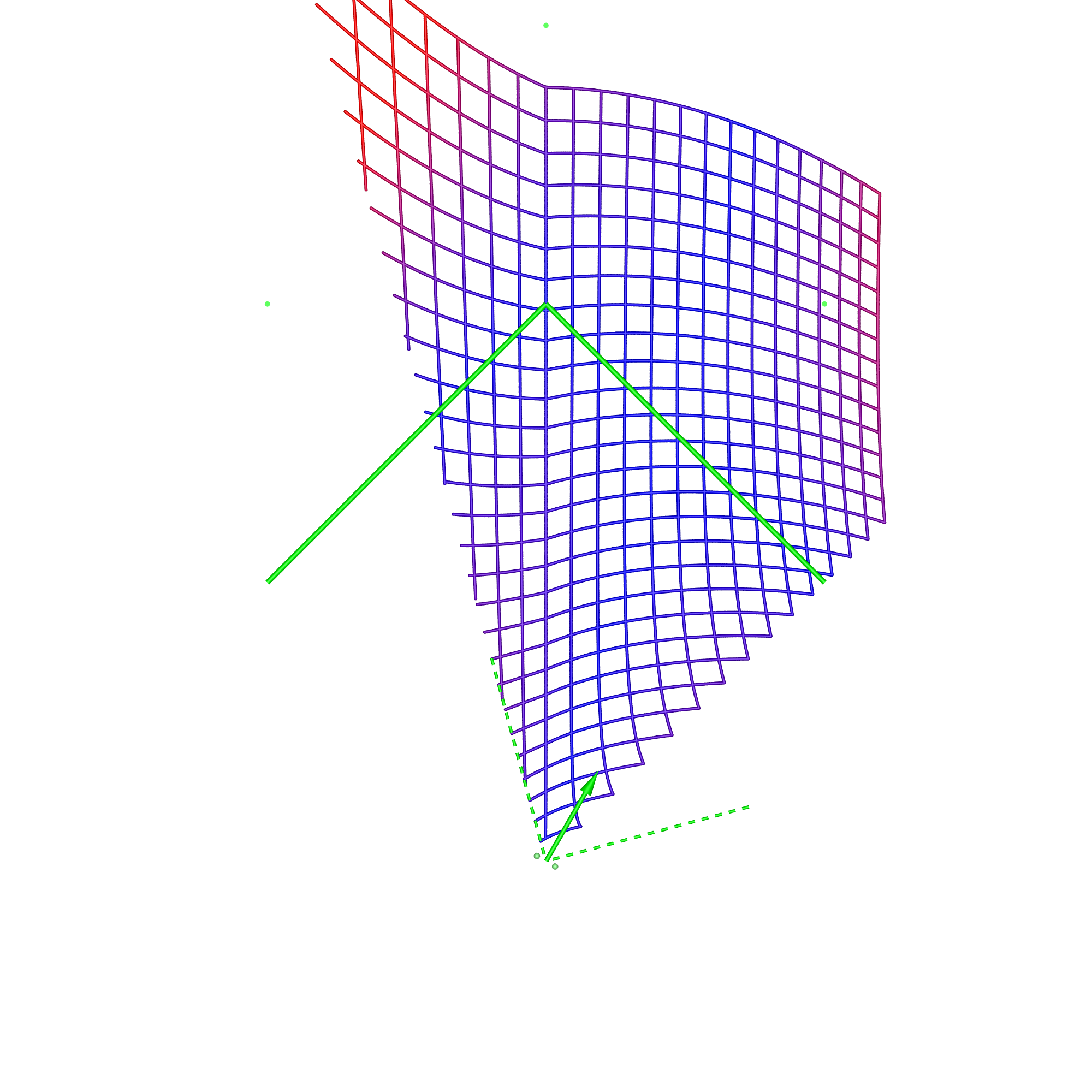
In each of these diagrams blue represents no spatial distortion, that is, an object in the scene appears in the correct position from the viewer's perspective. Not surprisingly in most of the cases here (omnidirectional stereoscopic panorama being the exception) there is no spatial distortion when the viewer is located in the sweet spot, the spot for which the stereoscopic images are created. Red grid points correspond to the perceived object position being 1m or more away from its correct position. As such the situation (top right) where the viewer is standing back from the screen illustrates the expected stretching of space. The case where the viewer is standing to the side (bottom left) illustrates the expected sheering of space. The case where the viewer has turned to the right is accounted for by the fact that a correct projection would see the effective eye separation getting narrower on the left of the field of view and wider on the right of the field of view. The consequence of not performing that correction sees objects on the left of the display being stretched out in depth and the object on the right of the display being compressed. Cylinder, directional panoramaDimensions: radius 2.5m, height 3m.
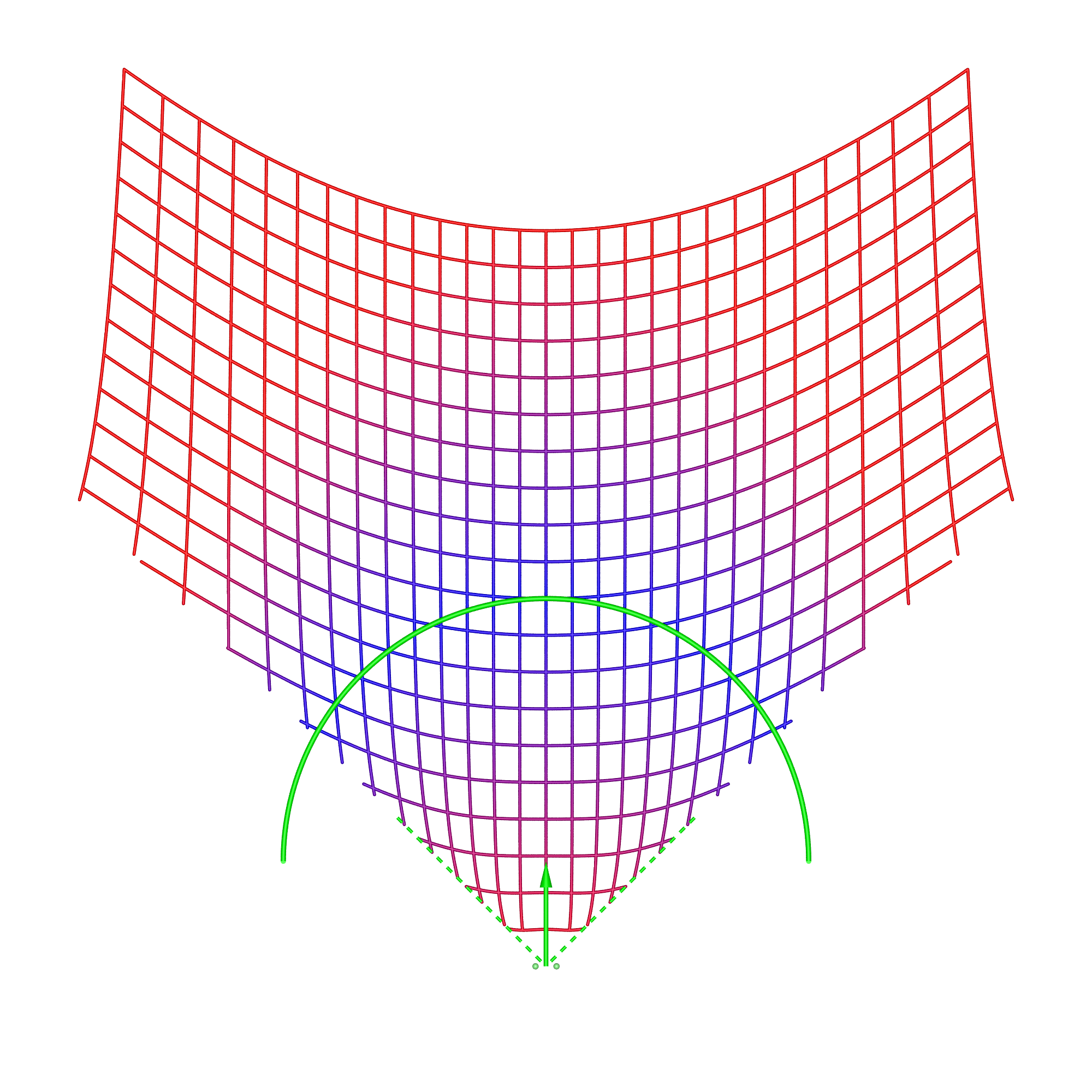
The reader should now be equipped with the thought processes necessary to analyse these simulation results. In the 1m back case for the directional stereoscopic panorama, one sees the familiar stretching of space but also some curvature being added. The large distortions near the viewer are rarely experienced because content is normally not brought so close to the camera, this also applies to the other cases presented here. Note that, as expected, in all these simulations the spatial error tends to zero as points tend to the depth of the screen surface. This is expected because objects at the display depth exhibit zero parallax irrespective of the viewer's position.
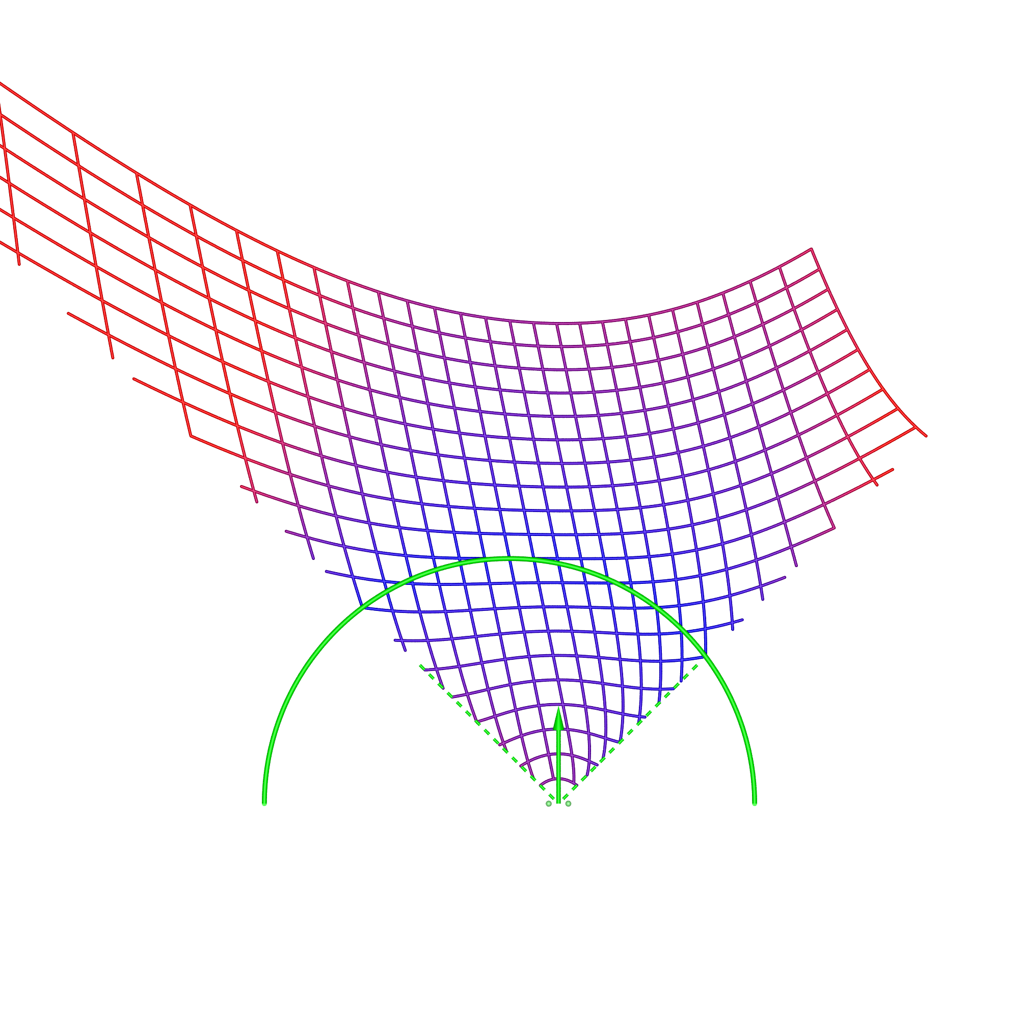
Dimensions: radius 2.5m, height 3m.
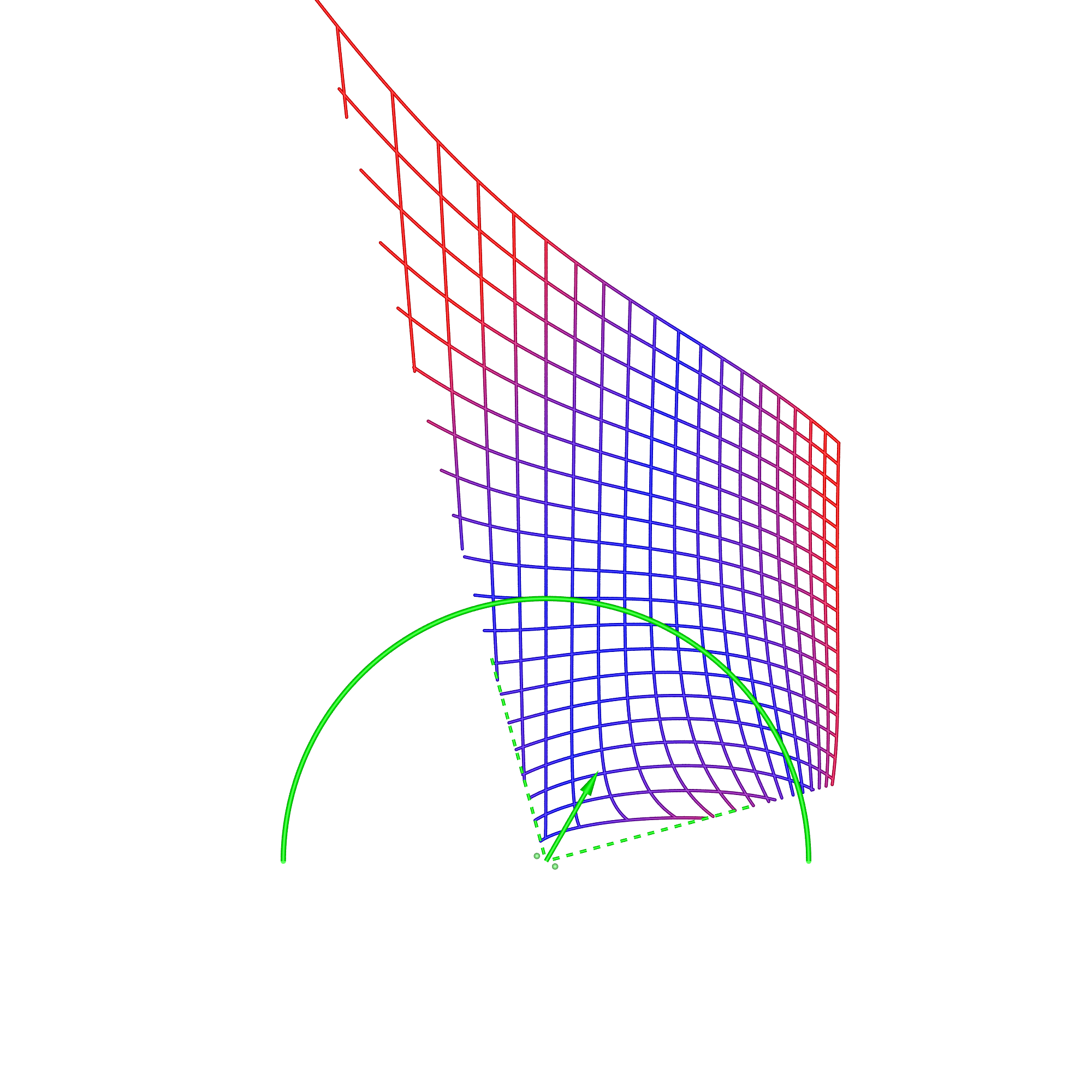
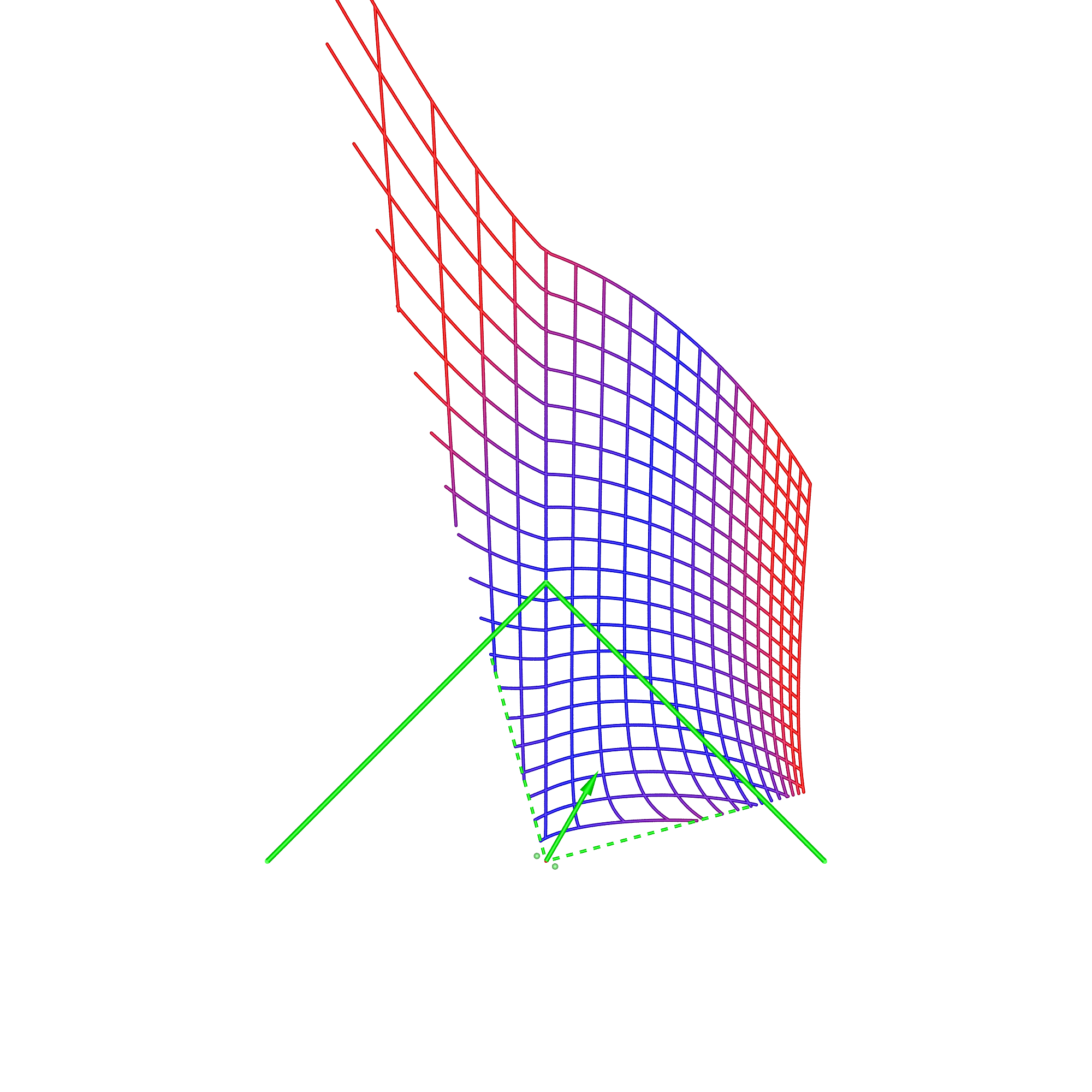
This is the only case where even though the viewer is located at the sweet spot (top left), there is spatial distortion. Given the method by which omnidirectional stereoscopic panoramas are created, this is no surprise, indeed it is intentional. The benefit of the omnidirectional stereoscopic panorama reveals itself in the case where the viewer is looking in a different direction (bottom right), here in contrast to the directional panorama case, there is no distortion along the line of sight of the viewer. It is this key feature that makes this projection the preferred choice for large cylindrical displays intended for multiple participants all of which could potentially be looking in different directions. Wedge, central locationDimensions: width of each wall 3.75m, height 2m.
The most noticeable feature in the case of the wedge is the discontinuity that occurs when the viewer moves off the central axis. It is understood by considering the sheering that occurs with a planar display wall except now the sheering is different for each wall. It goes part way to understanding why head tracking is key to displays made up of discrete planar surfaces, such as the original CAVE. Wedge, corner locationDimensions: width of each wall 3.75m, height 2m.
Compared to the previous case, if the viewer is standing on the corner of the box defined by the 2 walls of the wedge then the distortion effects are less. This is a reflection that at such a position less of the viewer's peripheral vision is engaged and the "wedge" nature is diminished. It approaches the case of the single display wall without any advantages but with the disadvantage of a seam in the middle for off-axis viewing. Summary Chart
|