Autostereoscopic lenticular imagesWritten by Paul BourkeDecember 1999. Update 2014
See also Calculating stereo pairs Introduction
Stereoscopic systems present the viewer with an image of a 3D object such that it appears to have "real" depth. The wide variety of techniques all involve presenting different views of the 3D object independently to each eye hence simulating stereopsis. Traditional stereoscopic systems employ an apparatus that keeps the left and right eye images directed solely at the appropriate eye, examples are head mounted displays (HMDs) or shutter glasses. In the world of stereoscopic displays the holy grail are autostereoscopic methods, that is, they don't require and special glasses or lighting conditions. Autostereoscopic displays are attractive because they offer the closest approximation to how we view the "real" world around us, unencumbered with external viewing apparatus. One of the easiest autostereoscopic images to generate are those called "selector screen methods" which include parallax barriers and lenticular sheets, both closely related techniques. The following will discuss the details of lenticular generation, by the end you should
Parallax barrier methods were known about in the early 1900's, they include the parallax stereogram and the related parallax panoramagram. These will be discussed first as they are easier to initially understand. The parallax stereogram consists of a fine vertical grating placed in front of a specially designed image. The grating is normally made of an opaque material with fine transparent vertical splits at a regular spacing. Each transparent slit acts as a window to a vertical slice of the image placed behind it, the exact slice depends on the position of the eye. 
The parallax stereogram image is made by interleaving the columns from two images. In the discussion here we will be concentrating on the cases where the two images are from a left and right eye perspective image of a 3D scene. This image and the vertical grating are arranged/aligned so that the left eye can only see the strips from the left eye image and the right eye can only see the strips from the right eye image. 
Parallax panoramagrams use not just a pair of images but a larger number of number images. These can be arbitrary images or images in a time ordered sequence in which case tilting the panoramagram will give the impression of motion. In this discussion we will consider the case where the images are from a number of appropriately ordered viewpoints about a focal point, the result will be a depth perception. The image behind the barrier is formed by laying strips from each sub-image next to each other. 
The viewer can move their head from side to side and see different aspects of the 3D scene, except at some position where a "flipping" occurs where the eyes see the wrong pairs. This occurs at the transition from the left most to right most view (green to blue transition below). This effect is minimised by using a large number of sub-images with a small angle between them. Unfortunately the number of images is constrained by the achievable resolution of the image and barrier screen. The flipping can also be reduced by maintaining a shallow depth of view. 
One of the constraints with barrier methods is that so much of the image is occluded that they typically need to be printed onto a transparent sheet and back lit. They are usually mounted in special light boxes/frames. An advantage is that the image and barrier sheet can be created through the same printing process resulting is a matched image and barrier thus reducing many of the distortion effects that plague lenticular sheets. "Lenticule" is a synonym for "lens" but has come to mean a sheet of long thin lenses. Lenticular sheets contain a series of cylindrical lenses moulded into a plastic substrate. The lens focuses on an image on the back side of the lenticular sheet. The lenticular image is designed so that each eye's line of sight is focused onto different strips. The image placed behind the lenticular sheet is formed in essentially the same way as for a parallax panoramagram. 
The key to successful creation of autostereoscopic images based upon lenticular sheets is the quality and uniformity of the lens. The sheet is usually made so that the back side of the sheet is exactly one focal length behind the lens so that the image data emerges collimated from each individual lens. Unlike the barrier methods, the whole surface of the lenticular sheet radiates light, there are no opaque slits. Creating the composite image from the sub-images
The way the individual images are interleaved to form a composite lenticular image has already been outlined. The general case is illustrated below for N sub-images that are interleaved to form a composite that is N times wider than the individual images. Note: it is assumed that the N sub-images are all the same size and correctly registered. The final image is stretched vertically so as to form a lenticular image than is of the same proportions as the sub-images but N time larger (vertically a well as horizontally).
It should be noted that the final stretching could be performed just before printing, that is, the vertically stretched version need not be saved. This is a worthwhile consideration given that composite images tend to be very large and that run length encoding normally runs horizontally and thus the vertical redundancy won't be compressed. Of course one could use run length encoding on a rotated version of the lenticular composite. Note also that the image would ideally not be compressed with a lossy compression scheme. Creating the sub-image from a 3D model
For all these techniques any set of sub-images can be used. They might be images arranged as an animation sequence or indeed they could be totally unrelated images. These give rise to the lenticular special effect cards often used for advertising. The discussion here will be on creating autostereoscopic lenticular images from virtual 3D geometry, the earlier discussion is enough to form lenticular sheets of animated or arbitrary sub-images. The creation of lenticular sheets from real photography will not be discussed although the technique is the same but it requires sophisticated camera mounting hardware. Creating the N sub-images from a computer based 3D model and rendering package only requires precise positioning of the camera and frustum. In the same way as there are two ways to create stereo-pairs, toe-in and off-axis, the same applies to creating the series of images for lenticular displays. The toe in method illustrated below rotates the camera around a single point and symmetric camera frustums are used. This is not the correct method although it does work but with distortion, namely vertical parallax. 
The correct approach is to offset the camera along a linear path, ideally this involves using a off-axis frustum although a symmetric frustum can be used but the image needs to be trimmed appropriately in order to line up correctly.  Notes Printing
There are some considerations when printing images for lenticular sheets. The output device needs to have sufficient resolution to print the composite image without dithering across each pixel. For example if you use a 40 line per inch lens, and ten sub-images then the printer must be capable of 400 dpi. In practice you can use a printer that has a resolution of an integer multiple of 400 dpi. It is important to realise that the printer must be able to print whatever colours you use at that resolution. For example, a colour printer that uses 3 dyes say might be rated at 400 dpi but only if you use those exact 3 colours, any other colour needs to use a dithered combination of the 3 dyes resulting is a much lower real resolution. The best printers for making composite images are high definition continuous tone printers. Alignment
It goes without saying that alignment of the composite image onto the back of the lenticular sheet is critical for good results. Looking through the sheet at sharp edges on the image or it's border is an ideal way to getting the image aligned vertically. If the image "jumps" when looked at directly simply shift the lenticular sheet horizontally so the "jumping" occurs when the image is viewed from slight angles. File sizes
Composite images can get very large, it's a good idea to make some rough calculations before jumping in. Considering an RGB image with 3 bytes per pixel (24 bit image), if the sub-images are each 400 by 300 say, and there are 10 such images. The final composite image will be 4000 x 3000 pixels. This is 4000 x 3000 x 3 / 1024 / 1024 MB = 34 MB. Unfortunately the file size increases by the square of the linear size, so for 800 x 600 sub-images the file size rises to 137 MB. Software
The following bare-bone C code lenticular.c takes a series of images in a simple PPM format and forms a height stretched lenticular composite image. Please note that this is not a end user package but rather a starting point for those who are familiar with C/C++, it could be readily modified to handle different file formats. References
Update 2014: Calculating barrier strip parameters
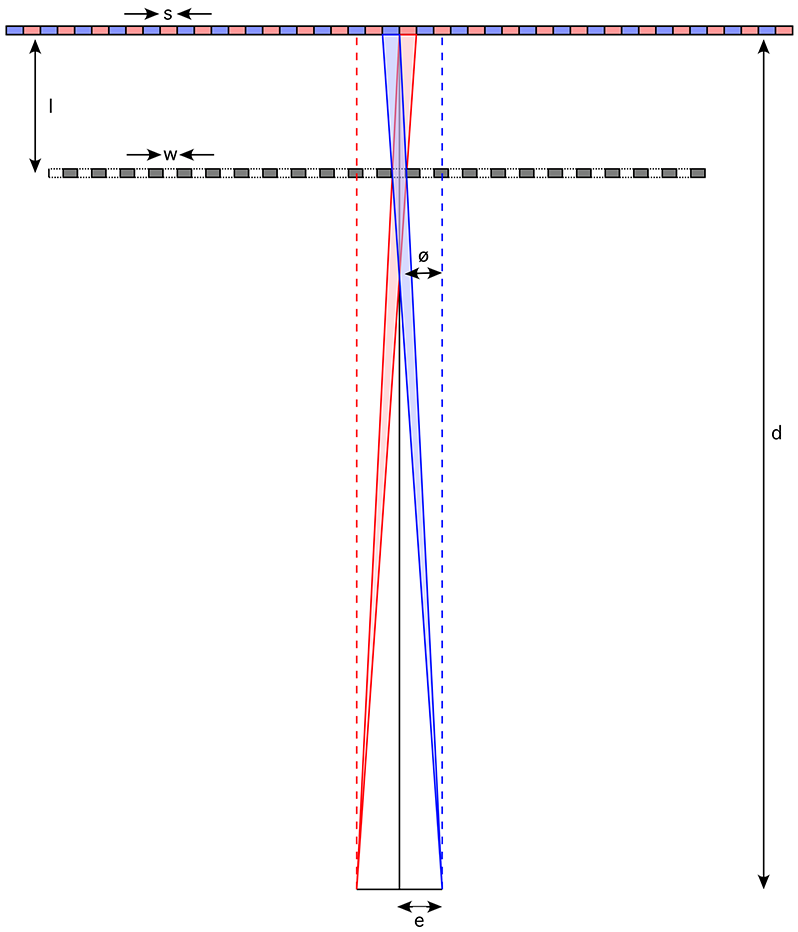
In order to create a lenticular print one needs to be able to determine two key dimensions, the width of the barriers in the barrier strip and the distance of the barrier plane from the image plane. The following diagram illustrates, in an exaggerated way, the principle of where the barrier needs to be and the barrier widths. It should be noted that the optics as shown falls down as one moves away from the center of the image, for this reason the viewer is normally expected to be very much further away than the barrier (and multiplexed image) slits. 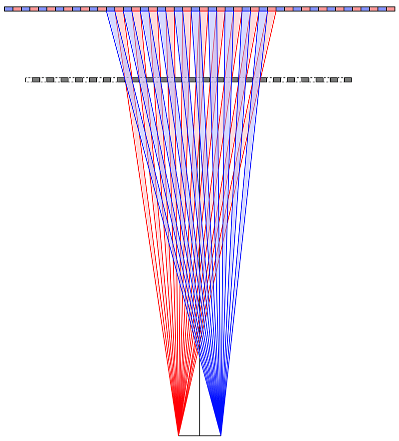
The following gives the key dimensions of a barrier strip print. Given an image multiplex slit width "s", a distance "d" to the viewer, and a half interocular separation of "e", then the angle "ø" is given by
The distance "l" of the barrier to the image plane is
The barrier strip widths are given by
Presentation: Lenticular Prints, August 2014. Paper: Novel physical representations for the visualisation of science data and mathematics. April 2015 Poster: Autostereoscopic lenticular prints for data visualisation. December 2014 References
|