Glasses free stereoscopic presentation: A selective reviewWritten by Paul BourkeDOI: 10.13140/RG.2.1.5064.5601 June 2015 See also: OzViz 2015 presentation slides Introduction Stereoscopic 3D viewing has well established applications in science visualisation, virtual reality, gaming and entertainment. Irrespective of the technology employed is the fundamental principle that two images need to be independently presented to each eye. This has traditionally been achieved by employing a device to physically block one of the image channels from the eye it is not destined for. The earliest example is the Wheatstone stereoscope in circa 1838 which employed a pair of mirrors to present an image only to each eye. This was followed the more popular Holmes stereoscope in 1861 that provided a mount for two photographs and a lens system to present each image to the relevant eye. The modern equivalent to these physical separation devices are head mounted displays (HMD), currently popularized by devices such as the Oculus. Fundamentally, from a stereoscopic perspective, they are little more than a digital version of the Wheatstone stereoscope, LCD displays rather than photographic prints. In more recent digital times there have been three main approaches to glasses based stereoscopic displays, these are based upon either: shutter glasses, polaroid or infitec filters. Not discussed are anaglyph based stereoscopic methods that employ coloured filters, typically red-cyan/blue. While these have the advantage of being able to be represented in print, the colour fidelity is so poor that they are not practical for the applications to visualisation focused on here. Shutter glasses work on the principle that the left and right eye images generated by a computer are multiplexed in time, typically at 120Hz. Active LCD panels in the glasses alternatively become opaque or transparent thus revealing each of the image pairs to the matching left or right eye. The last remaining detail is the synchronization between the computer generation of the left/right image and the glasses, this is typically achieved with infra-red or radio frequency signals, sometimes with a physical cable. This technique which originated from the virtual reality development of the late 80's is well entrenched in so far as quad-buffer graphics cards designed for stereoscopy provide the synchronization signal. Polaroid based stereoscopic viewing generally involves two image sources (projectors) each with a polaroid filter to polarise the light either linearly or circularly. Linear polarisation is the simplest but precludes head tilt so is suited more to seated rather than virtual reality applications. The glasses have matching polaroid filters as those on the projectors, the result being that each eye only sees the image it is supposed to see. There are a number of variations on this, the most common being a combination of an active stereo computer system with an active circular polarizer. Infitec based stereoscopic 3D systems encode each image in wavelength, narrow band filtering the wavelengths shifted in one direction for the left eye image and the other direction for the right eye image. Matching filters in the glasses serve to isolate these two images for each eye. As with polaroid system the most common configuration is a twin projector arrangement. Each of these approaches has their relative merits. Polaroid based systems have an advantage for public displays due to the low cost of the glasses compared to shutter glasses. Polarised systems also place fewer constraints on suitable graphics cards, essentially any graphics card can be used. Infitec have high degrees of channel separation at the expense of colour representation and require careful and regular calibration, the key advantage of Infitec is the low ghosting levels. They all have the disadvantage of requiring the viewer to wear some sort of eye-wear. Besides the "unnatural" aspects there are also some more practical issues such as shutter glasses interfering with some lights and affecting the use of LCD (polarised) panels, Infitec glasses are affected by glancing light from other sources, and interaction with existing prescription glasses. There are a number of options by which stereoscopic 3D material can be presented to a viewer without the need for glasses or other mediation device, this is known as autostereoscopic viewing. As with most technologies the principles are not new, but rather re-invented for a digital age. Not discussed here are so called "free viewing" techniques involving tricks the viewer employs with various levels of visual acrobatics, while some people can train themselves most find it problematic. In what follows four technologies will be introduced, in each case they are representative of the current state of the art, at least at the time of writing. Two of the technologies are print only formats and the other two have digital versions, the consequences of the later is they are amenable to time varying and interactive content. Without glasses to mediate which image is seen (and which is not) by the eyes, the following technologies need to rely on creating spatial zones. That is, from a position P1 one image is visible only, and from an offset position P2 another image is visible only. High resolution tablet and barrier strip
As with most technologies we may think are new, barrier strip images have a rich and old tradition. In 1692 the French painter G. A. Bois-Clair created multiplexed paintings with a grid of vertical slats in front. Similarly almost everything we do with digital imagery today was explored in the early days of photography. The possibility of barrier strip photography and viewing was discussed by Auguste Berthier in 1886 and the first evidence of construction was by Frederic Ives in 1901. One of the first digital devices was released in 2002 when Sharp started manufacturing switchable 2D/3D barrier strip displays. In order to create a barrier strip image one needs to be able to precisely model a number of parameters. These include the spacing of the multiplexed image, the width of the barriers in the barrier strip and the distance of the barrier plane from the image plane. The following diagram illustrates, in an exaggerated way, the principle of where the barrier needs to be and the barrier widths. The right eye (blue) only sees the even image strips, the left eye (red) can only see the odd image strips. If the even and odd image strips are derived from a stereoscopic image pair then stereopsis is achieved. It should be noted that the optics as shown falls down as one moves away from the center of the image, for this reason the viewer is normally expected to be very much further away than the barrier (and multiplexed image) slits. 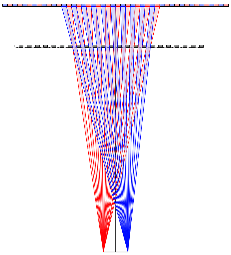
The key characteristics of these displays is the sensitivity to viewing position. Slight movement from the correct viewing zones results in the eyes seeing the opposite image to what they should see. Due to motion parallax and the humans visual systems desire to see 3D, the flipping isn't always obvious but does result in high eye strain. An advantage with barrier strips is that existing stereoscopic content can usually be used although the depth budget is much less than most glasses based stereoscopic systems can support. As with most technologies presented here the resolution of the final product is lower than the capabilities of the underlying media. In this case it is simply a factor of 2 horizontally. The Taiwanese "no-name" tablet explored here has a high resolution display with an additional front layer of LCD. This front layer can be transparent during normal tablet operation and becomes the barrier strip when in 3D mode. This has the additional feature of supporting stereo in both landscape and portrait modes. 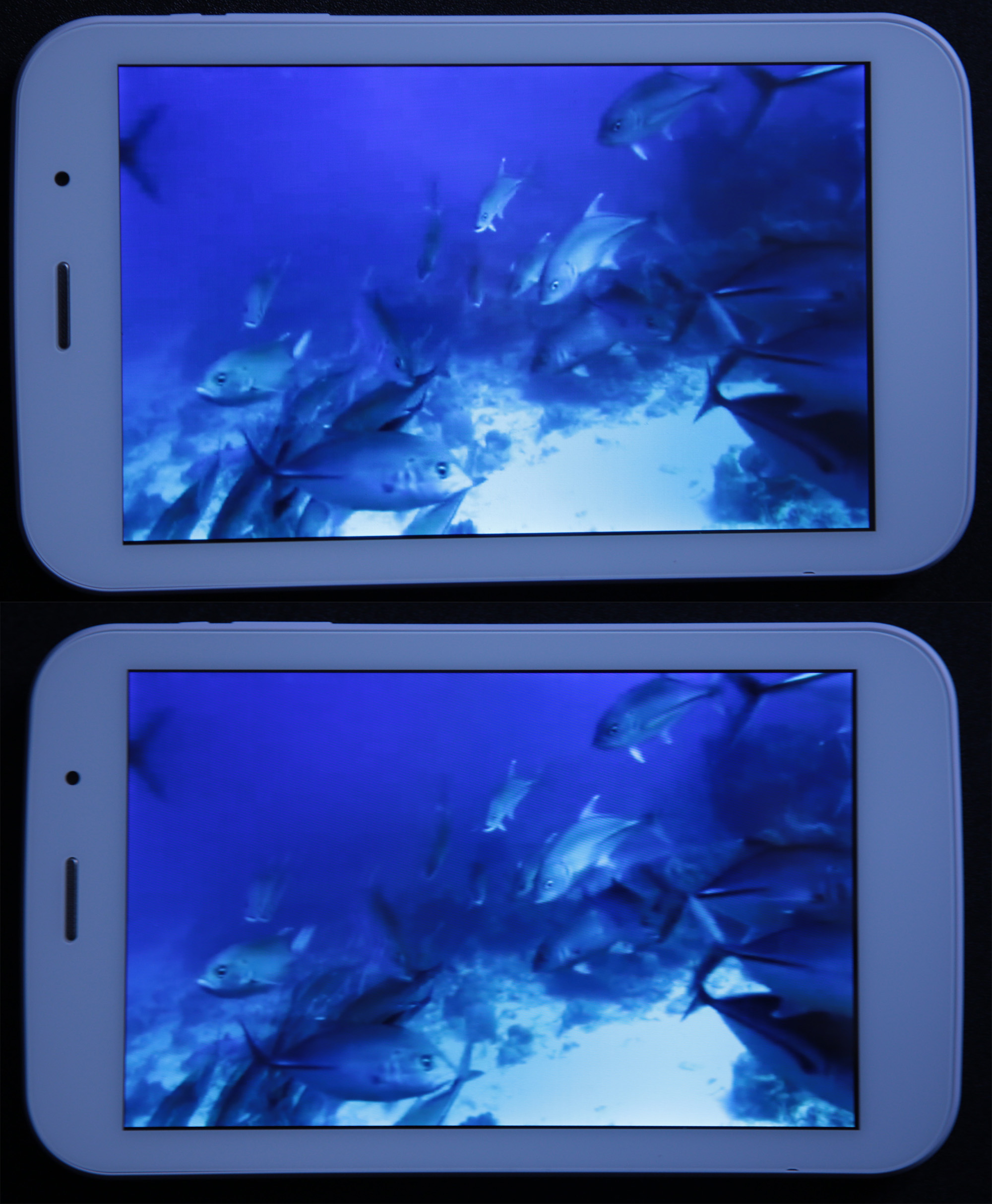
Lenticular 4K panel
As per the comments above regarding barrier strip displays, the possibility of using lenticular arrays is also not new. One-dimensional arrays of cylindrical lenses were patented by Walter Hess in 1912. They have been popular from the 1940 to create "flip animations" in the advertising industry where instead of being used to convey stereopsis and parallax, were simply used to present a series of images. It is equally possible to encode both different scenes and have each scene with stereos3D depth. The technique was popularised again in the 1960, for example, cover of the Rolling Stones "Their Satanic Majesties Request". The peak for lenticular autostereoscopic displays was around 2008 and Philips created the WOWvx screens in 2009. In general, unlike lenticular based prints, these early attempts suffered from insufficient panel resolution and only a few producers have survived. With the recent release of 4K and 5K LCD panels there is potentially an increased interest in lenticular displays for other than the novelty for digital signage. The display tested here is from Alioscopy and based upon an underlying UHD (3820x2160) panel. This is one of a new range of lenticular based displays that will increasingly benefit from higher resolution panels. The main observation was the limited depth budget. This display uses up to 8 images and as such existing stereoscopic cannot be used directly. Various tricks are available to convert stereo pairs but, like similar methods to create stereo content from non-stereo content, the results are less than optimal. As expected, the best results are achieved with custom content, that is, content created optimally in terms of what the technology can support as well as with a knowledge of the limitations. In the example below a 3D model in UnityPro of a rock art site in Western Australia. In the authors opinion while these displays can support interaction and mealtime content, the limitations on depth budget limit them to carefully crafted and choreographed animations, they are not suited to navigation within general 3D scenes. 
One might be tempted to imagine that for a 8 image panel the horizontal resolution is divided by 8, in this case to a very modest 512 pixels horizontally. In reality it isn't as bad as that due to clever consideration of the individual LCD colour arrangement. With viewing ranges of around 1.5m and quite precise viewing positions due to the available (only) 8 views still limits the applicability of these displays for serious visualisation applications. Noting that closer viewing would probably required a more complicated lenticular filter arrangement. Another disadvantage compared to the LCD barrier strips is the lenticular lens sheet is fixed precisely in place, this makes the panel largely useless for anything other than the intended autostereoscopic use. Another slight consideration of lenticular lens sheets is their delicacy, this is true for this panel and the lenticular prints discussed next. Lenticular prints
Lenticular prints, unlike those based upon digital panels, are capable of higher resolution (300DPI to 600DPI full colour) and are thus able to encode a much higher number of images. As such the viewing zones are also generally wider, the prints created here are readily capable of ±15 degrees by using around 30 images. The example below created by Fuzed and at A3 size shows the wide range of parallax that can be achieved, of course all views between the two shown are have 3D depth. 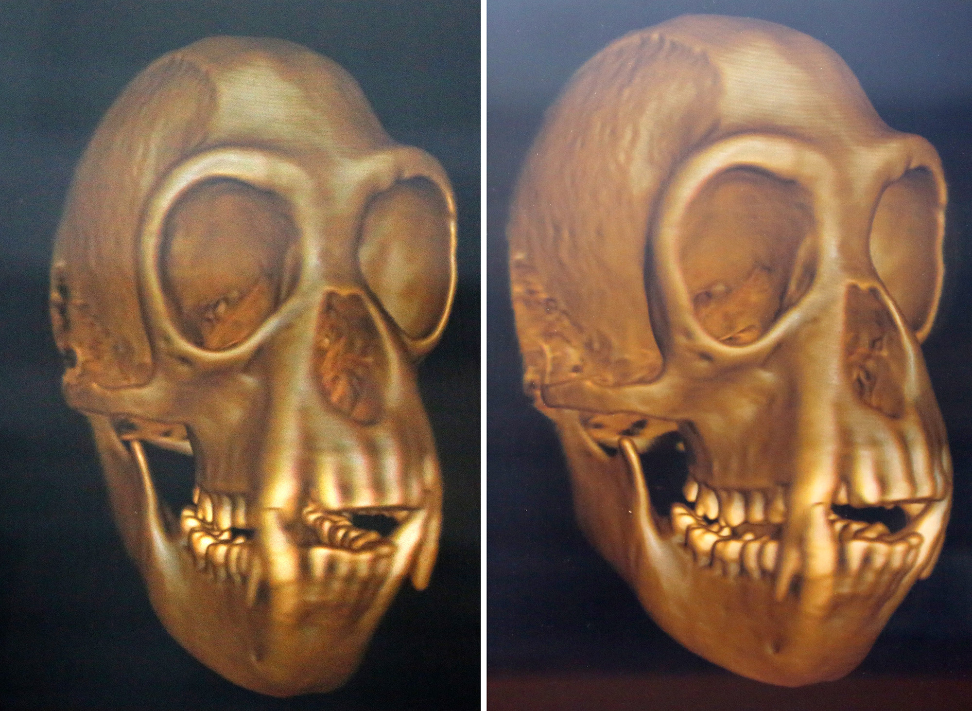
Image creation for all the technologies presented here involve rendering of the computer model from a number of positions. Each virtual camera is pointing in directions parallel to it's neighbours, in other words extending the parallel offset camera technique. See diagram in next section. While the discussion here is around computer generated/rendered content, there are photographic and even video capture opportunities. These become more challenging as the number of required views increases. Digital still cameras on a linear dolly can readily capture the 2, 8 or 30+ photographs required. Granted a single camera capture is for a stationary subject, although multiple camera rigs are readily possible for 2 or 8 views. Synthetic holograms
Traditionally holograms require a real object and the interference pattern between two laser beams is recorded onto film. The ability to encode an approximation to the light field are variably called iLumograms (Geola) or more simply synthetic holograms. When use to encode animation they are often referred to as holographic panoramagrams. Their main advantage over the techniques discussed above is their much wider viewing angles, ±45 degrees is readily achieved. In addition they do not suffer from the eye swapping as one passes between the viewing zones. The synthetic holograms presented here should not be confused with computer generated holograms that attempt to compute the actual light field. Such true holograms are still computationally prohibitive, at least for "interesting" scenes and objects. All holograms require some degree of lighting, when unlit these synthetic hologram just appear to be a black sheet of film/mylar. The light here is a 50W white halogen lamp, as an approximation to a coherent source. The example created here is a reflection hologram and a little smaller than A3 size, it is equally possible to create transmission holograms these have the light behind the hologram plane. Unlike real holograms these prints do not suffer from the same rainbow colour effects. 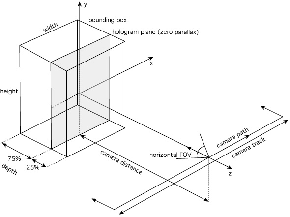
The number of images rendered is typically orders of magnitude higher than for the techniques already discussed. The example below has over 1000 images for only horizontal parallax. Synthetic holograms with vertical parallax are also possible at a cost of lower resolution but then have the ability to be viewed from surrounding positions. 
A consequence of the requirement for the resolution of film and the larger number of images required mean the real-time generation is unlikely in the near future. Another consequence is the relatively high cost especially for larger scale prints. For example the cost of the synthetic hologram above is an order of magnitude more than the equivalent lenticular print. Comparative summary
The following summarizes some of the key parameters of the technologies tested. It should be noted that there is variation between many of these parameters, for example many of the devices are available in other dimensions and configured to different viewing distances.
References
1. Ultra-Realistic Imaging: Advanced Techniques in Analogue and Digital Colour Holography. Hans Bjelkhagen, David Brotherton-Ratcliffe. Taylor & Francis. 978-1-43-982799-4 2. Progress in projection of parallax-panoramagrams onto wide-angle lenticular screens. True 3D Imaging Techniques and Display Technologies. D.F.McAllister, W.E.Robbins. SPIE 761, pp35-43, 1987. 3. Computer Generated Lenticular Stereograms. Non-Holographic True Three -Dimensional Display Technologies. W.E.Robbins, Proc SPIE 1083, 1989 4. Computer Generated Barrier Strip Autostereography. Sandin, Daniel J., et al. Proc SPIE, Non-Holographic True 3D Display Technologies, 1083 Jan 1989, pp65 5. Theory of Parallax Barriers. Kaplan, S.H. J.SMPTE 59, No 7, pp 11-21, July 1952 6. A Camera for making Parallax Panoramagrams. Ives, H.E. J. Opt. Soc. Amer. 17, pp 435-439, Dec 1928 7. Autostereoscopic 3D Displays. Dodgson, N.A. (August 2005). IEEE Computer 38 (8): 31–36. doi:10.1109/MC.2005.252. ISSN 0018-9162. 8. Multi-View Autostereoscopic 3D Display. Dodgson, N.A.; Moore, J. R.; Lang, S. R. (1999). IEEE Computer 38 (8): 31-36. doi:10.1109/MC.2005.252. ISSN 0018-9162. 9. Images stereoscopiques de grand format. Berthier, Auguste. (May 16 and 23, 1896). Cosmos 34 (590, 591) 10. New Autostereoscopic Display System, Ezra et al, SPIE Vol 2409, February 1995. 11. Flat Panel Autostereoscopic Displays - Characterisation and Enhancement, Woodgate et al, SPIE Vol 3957, January 2000. 12. A Camera For Making Parallax Panoramograms, H. Ives, J. Opt. Sci. Amer. 17, pp. 435-439 (Dec. 1928). 13. Current Technology in 3D Electronic Displays, R. Guzik, Electronic Imaging 88 Anaheim, Calif. (Mar. 30, 1988). 14. Three-Dimensional Imaging Techniques. Oshkosh, Takanori, Atara Press (2011), ISBN 978-0-9822251-4-1 |