Adventures with the LookingGlass PortraitWritten by Paul BourkeNovember 2021
The following documents various content creation options for the LookingGlass displays. The examples presented are for the Portrait model but the principles apply to the other products in the range, and indeed to other lenticular type displays. As with any documentation of a technical nature there are some aspects that may become dated as the supplied software improves or otherwise changes, but the principles will endure. This document may at times refer to the word "holo" or "hologram", this is accidental and will only be due to that branding by the companies marketing department. The LookingGlass products are of course not holograms, in the same way as Augmented Reality technologies are not "holographic". The underlying technology being employed here is known as lenticular which has a rich history, including being used for presenting stereoscopic photography as early as the late 1800's. This is not meant to belittle the LookingGlass products, indeed they have been a breakthrough range in terms of price and quality, it's just a shame they feel the need to use the word "holographic". There are four options supported by the supplied software for creating content for the LookingGlass, three will be presented here because those are of most interest to the types of imagery the author would like to present. Specifically rgb image and depth map (RGBD) pairs, so called quilts and light field image sequences. All of these approaches can be applied to single images as well as movie sequences. This document does not discuss the image interleaving that needs to occur for any lenticular display. This is highly technical and well outside the scope of this discussion. For the LookingGlass products one is supplied with an application called "HoloPlayStudio" which encodes the imagery supplied, sometimes called "lenticularising". One should note that one reason for the price point and success of these displays is that the lenticular image is assembled uniquely for each device, compensating for the variations that arise when mounting a fine lenticule. As such, while one can copy the interleaved lenticular movies from the device, they should not be shared with other displays. Rather the RGBD or quilts should be shared and reprocessed for each display it will be presented on. In the following the RGBD and quilts used for demonstration will be provided. RGB image and depth map
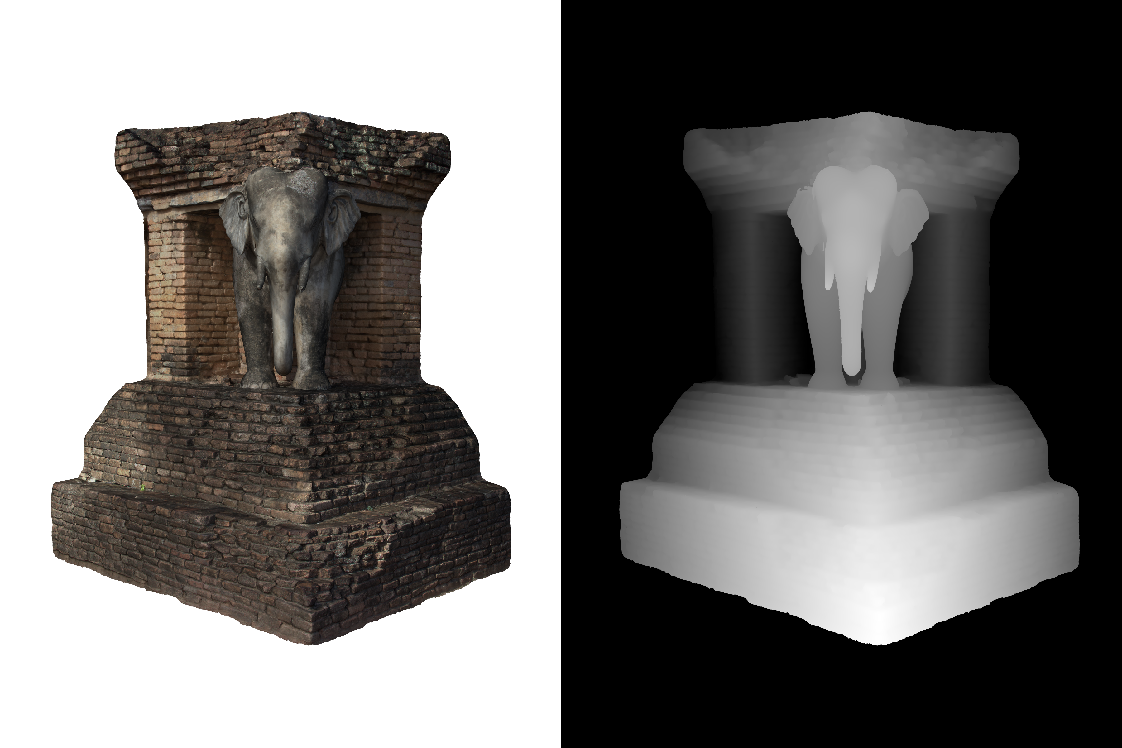
This is the simplest way to present an image with a sense of depth. In the LookingGlass terminology it is called a RGBD image (RGB image + Depth). The same technique is used in a range of other products including "3d images" on the FaceBook platform. The HoloPlayStudio allows each half of the RGBD image to be arranged in various ways, left-right, top-bottom. A left-right arrangement is shown below.  RGBD image
Fairly obviously, white corresponds to the closest objects in the scene and black to the furthest objects. Controls in HoloPlayStudio allow one to adjust the degree of depth (mapping grey values to the desired depth range) and the focus depth. Two more examples are provided below, both based on 3D models reconstructed using photogrammetric techniques.
These are a weak form of 3D presentation since a depth map cannot represent occluded objects, this is very evident in the beggar statue above, one cannot look behind foreground objects. RGBD images are more correctly referred to as 2.5D (a 2D plane + a height map). There are many ways of creating the depth maps from 3D models, the approach used above is described here. There are many other ways of creating RGBD images, another source are depthmaps computed during focus stacking. Although far from perfect, an example is given below of a cockroach.  RGBD image The reasoning is not clear but all content ends up being a movie on the LookingGlass storage. So still images whether they are RGBD or quilts of a single image are encoded into 10 second movies. Quilts
Loading full 3D images (or movies) is achieved using so called "quilts". These are simply a NxM grid of images, each image being a different view of the 3D model. The bottom left image is the left most view and the top right image is the right most view, the progression runs left to right, and then bottom to top. Like pretty much all stereoscopic image generation, the best way to get the rendering correct is to model the image plane of the display and the volume corresponding to the frame and supported depth in real world device coordinates. One places the virtual camera where the observer will be. The 3D model is then scaled to this coordinate system and translated to reside within the volume. The field of view of the camera corresponds to the angle the display subtends at the viewers eye. The expression for the horizontal field of view (FOVh) and vertical field of view (FOVv) of the camera is given as follows Where W is the screen width, H is the screen height and R is the distance of the viewer to the display center. The Portrait display is approximately 115mm width and 155mm high. If one is to view it from 500mm (the suggested optimum) then the horizontal field of view is 13.1 degrees and the vertical field of view is 17.6 degrees. The following illustrates the camera model for the above specification, to scale. This is the top view and one can create a similar diagram for the vertical field of view and frustum for the side view. 
If the scene/object is rendered as shown then the red parts that are in front of the display plane will appear in front of the screen, known as negative parallax. The blue parts of the model that are behind the display plane will appear behind the screen, referred to as positive parallax. Importantly, if everything is done correctly one should be able to predict exactly what depth parts of the model should appear when viewed on the the display, see later. There are three camera models one might imagine using to generate the views required for the LookingGlass displays. Each of these is intended to model the way the human viewer head moves when translating left and right. The approaches are illustrated below, they are respectively called "arc" mode, "slide" mode and "offaxis" mode (the authors terminology). In arc mode the camera is rotated in an arc centered on the the display plane. The camera is always pointed towards this center. When generating photographic content an object on a turntable would use this model 
In slide mode the camera is translated in a straight line. Like arc mode the camera is always pointing towards the center of the display plane. In traditional stereoscopic terminology these are referred to as "toe-in" camera models, in screen based stereoscopy they have undesirable characteristics. 
In offaxis mode the camera is translated along the same path as for slide mode but the cameras are always pointing perpendicular to this path. The frustum however is no longer symmetric about the camera pointing vector, hence the name "offaxis". This is the approach most commonly used for realtime computer generated material because these offaxis frustums are readily supported in realtime APIs, eg: OpenGL. Offaxis frustums are critical in almost all virtual reality environments. They are not always supported by offline raytracing software although they can be readily derived using symmetric frustums and clipping off the correct number of pixel columns from the appropriate side of the resulting images. Offaxis frustums is the strictly correct method although given the geometry of the system there is very little difference in the visual appearance on the display for objects contained within a modest view volume. 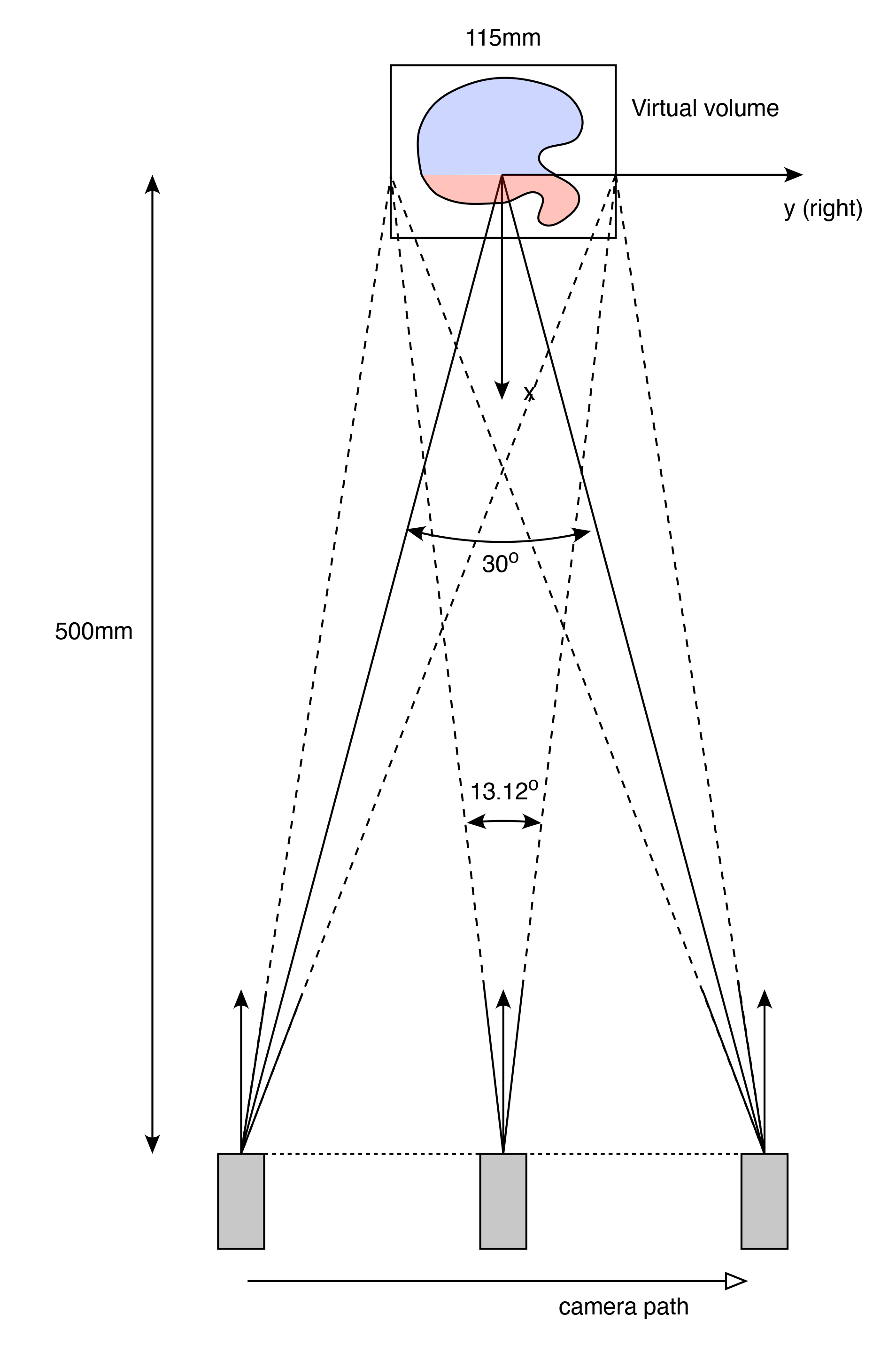
A parameter not yet discussed is the range of viewing angles that the viewer may move their head left and right. For the Portrait display 30 degrees (-15 degrees to 15 degrees) from the center axis is considered comfortable. This angle determines the left and right extent of the cameras in each of the modes above. One can create quilts over a range of grid sizes, in the following example it is a 8x6 grid of quilt patches. One also needs to decide on a quilt resolution, here a quilt of 3360x3360 pixels will be used. Please note that these are not particularly magic values, the HoloPlayStudio will successfully create the interleaved lenticular image for a wide range of grid densities and quilt resolutions. For the quilt grid and resolution chosen, each rendered image will be 420x560 pixels. While it makes sense for the patches of the quilt to be the same aspect as the display it isn't actually necessary. Note the Portrait device has a resolution of 1536 x 2048, or an aspect of 0.75, which is also the aspect of the 420x560 used for the quilt patches here. The 48 rendered frames will look something like the following. 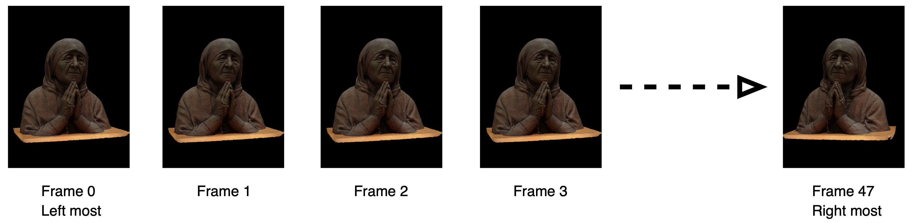
In preparation for HoloPlayStudio these need to be arranged into a quilt. There are lots of ways this could done, in the interests of automating the process the author uses "convert" that is part of the imagemagick package. convert 00.png 01.png 02.png 03.png 04.png 05.png 06.png 07.png +append row5.png convert 08.png 09.png 10.png 11.png 12.png 13.png 14.png 15.png +append row4.png convert 16.png 17.png 18.png 19.png 20.png 21.png 22.png 23.png +append row3.png convert 24.png 25.png 26.png 27.png 28.png 29.png 30.png 31.png +append row2.png convert 32.png 33.png 34.png 35.png 36.png 37.png 38.png 39.png +append row1.png convert 40.png 41.png 42.png 43.png 44.png 45.png 46.png 47.png +append row0.png convert row0.png row1.png row2.png row3.png row4.png row5.png -append grid$1.png rm -rf row?.png The resulting quilt is shown below, also available for download. Frame 0 is lower left, frame 7 is lower right, frame 47 is upper right ... and so on. 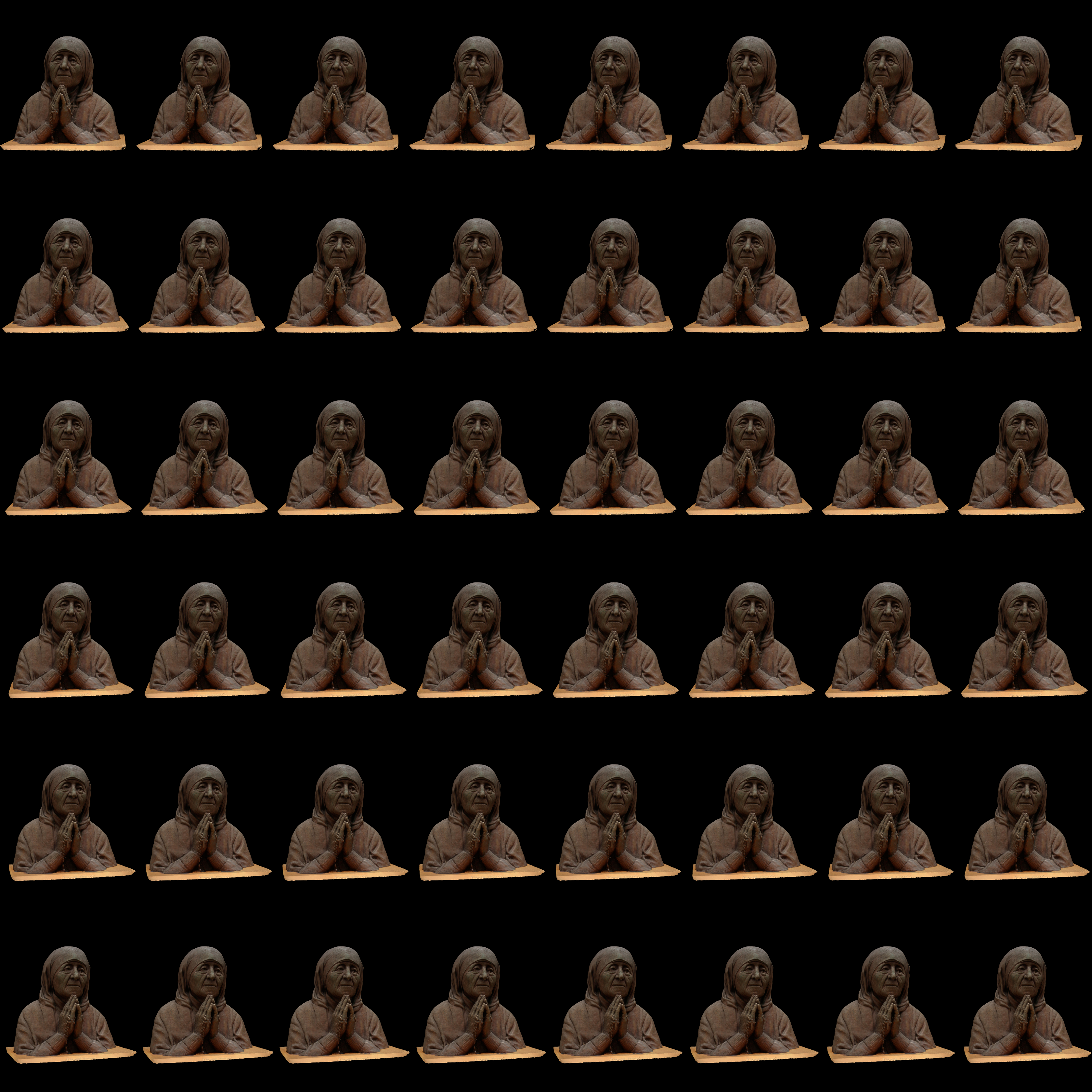 Quilt image
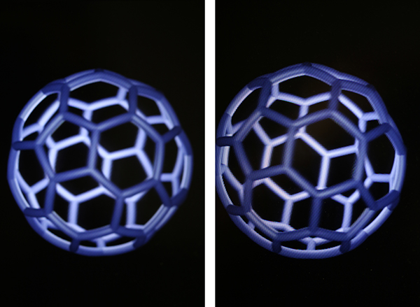
A couple of additional sample quilts of still objects.
It is obviously impossible to convey through other media what the quilts presented here look like, that can only be achieved with the LookingGlass display. The best one can hope to do is show photographs from two (or more) positions to illustrate that the display is presenting different views of the object from those positions. 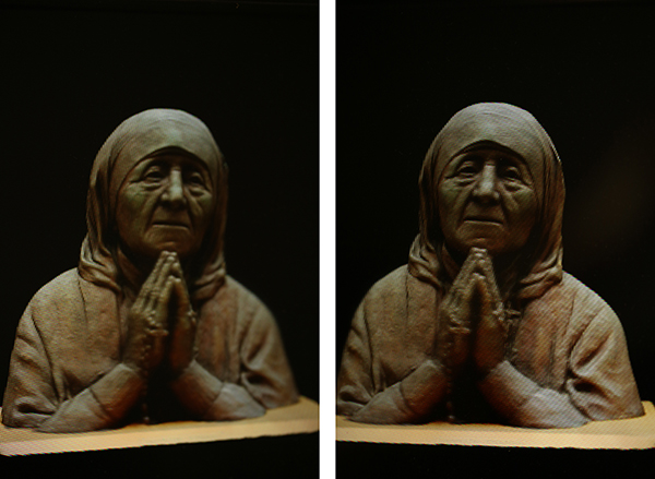
Quilt Movies
Quilt movies are a simple extension of the above, that is, each frame of the movie is a quilt at that time step. As an example here is a quilt movie of the above model simply spinning through 120 degrees about the vertical axis. Note that at the time of writing the default yuv444p colour encoding by ffmpeg is not supported, one needs to force yuv420p encoding. For example ffmpeg -r 30 -i grid%04d.png -c:v libx264 -crf 20 -pix_fmt yuv420p teresa.mp4 Light field input
The third method of supplying content to the LookingGlass is a so called light field. The camera model is a linear path, similar to the offaxis scheme above but with symmetric frustums. 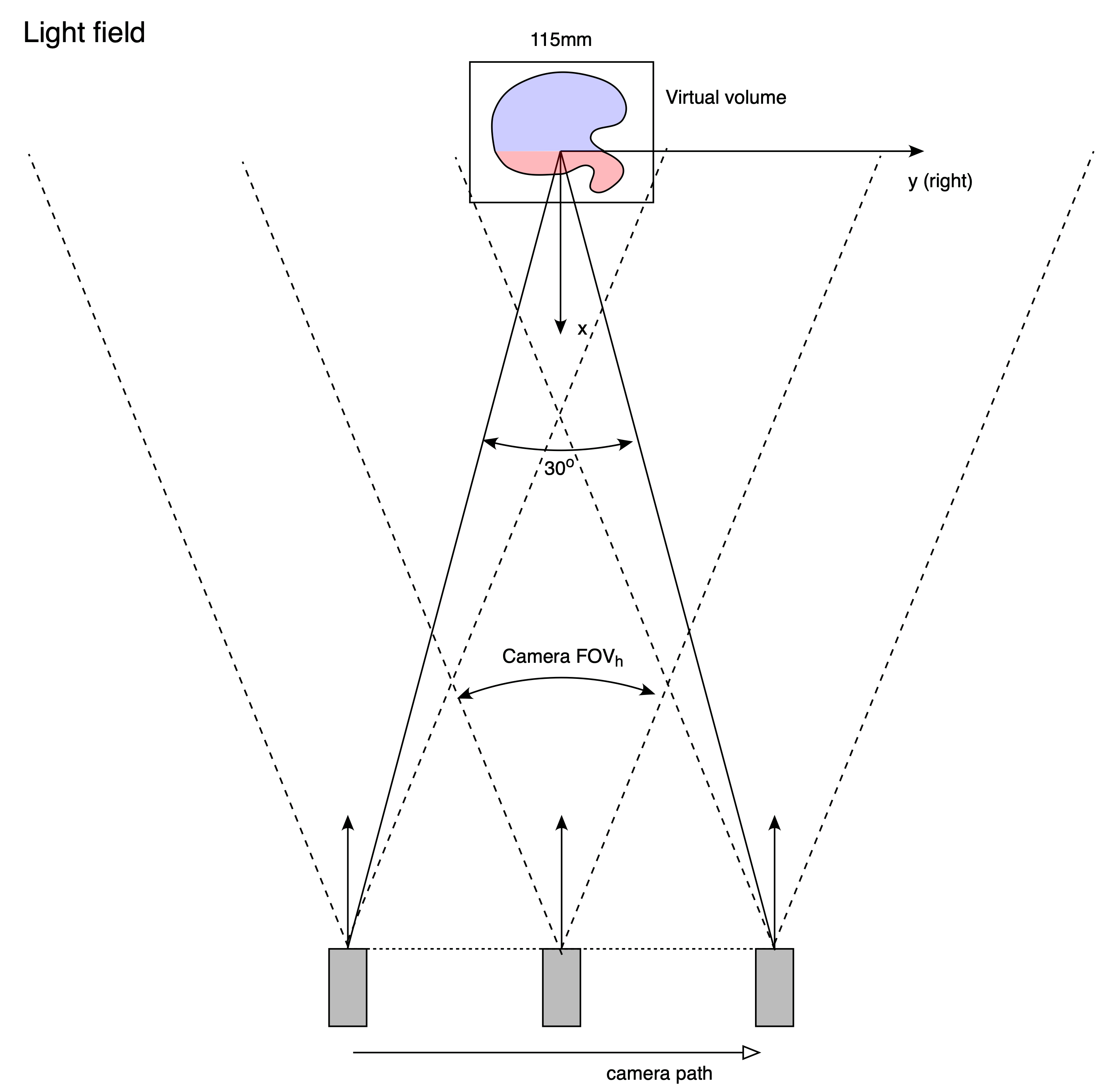
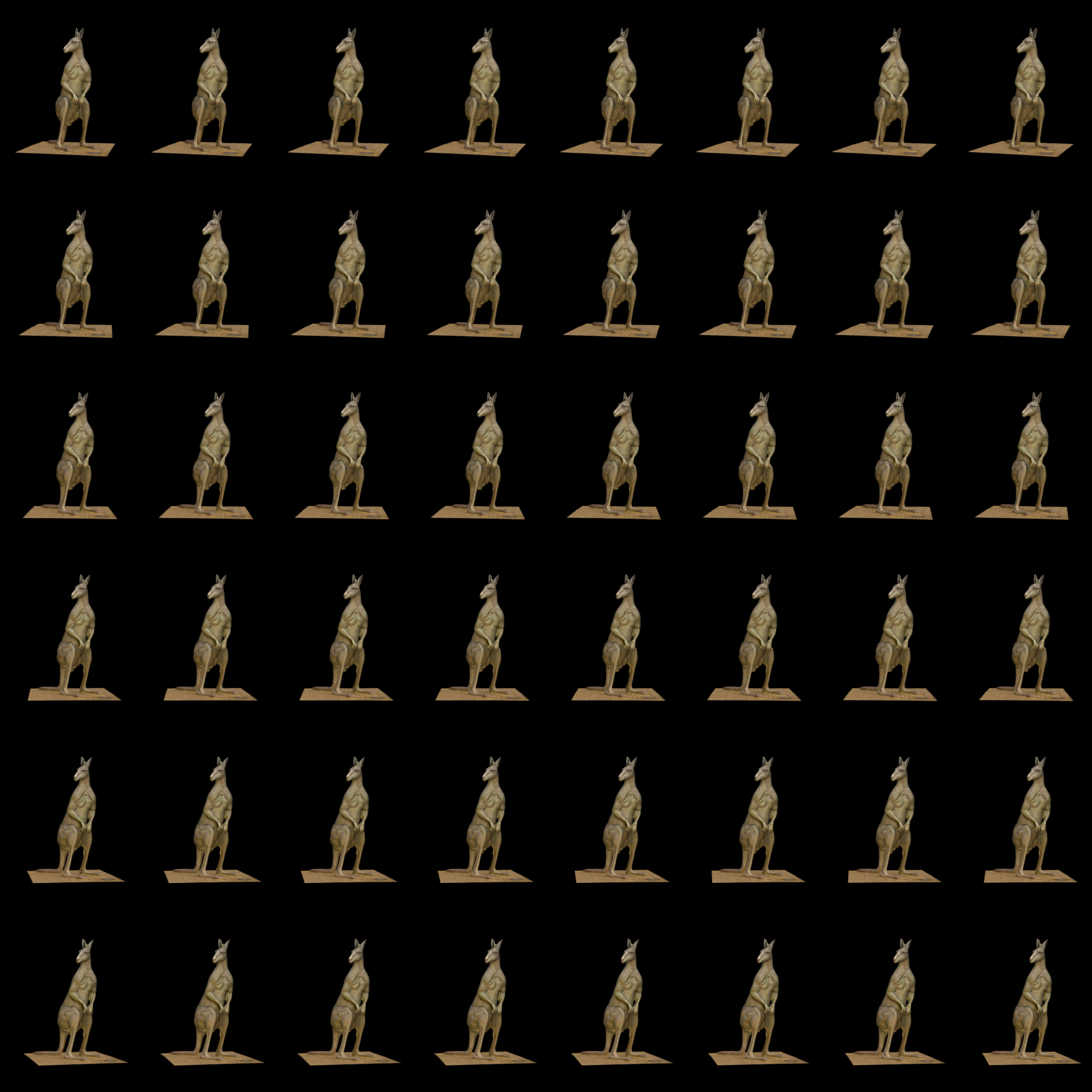
An example is presented below. Note that while this is illustrated as a quilt, the image sequence is presented as a folder of sequentially numbered frames to HoloPlayStudio. Slightly confusingly, the default order is the opposite to quilts, the frames for quilts are ordered left to right but for light fields they are ordered right to left. There is a swap order option in HoloPlayStudio. 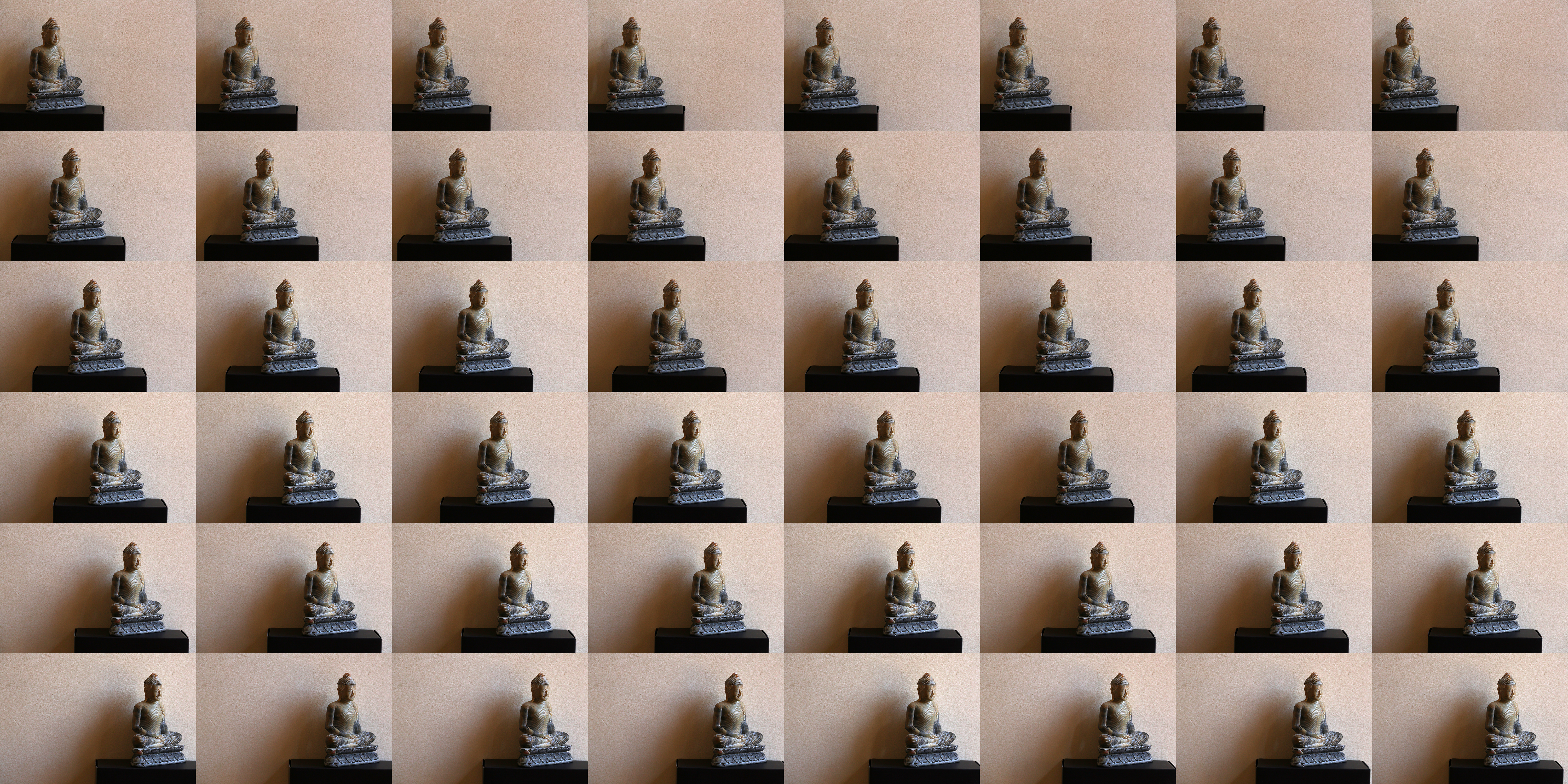
The object of main interest needs to be contained within all the frustums, as such one can work out the distance d the camera should travel given the range R of the camera from the subject and the horizontal field of view of the camera lens (FOVh).
Given the above photo set one could of course process the images to conform to the offaxis method described earlier, and present to the HoloPlayStudio as a quilt. So a redundancy in these two approaches. An example is shown below. 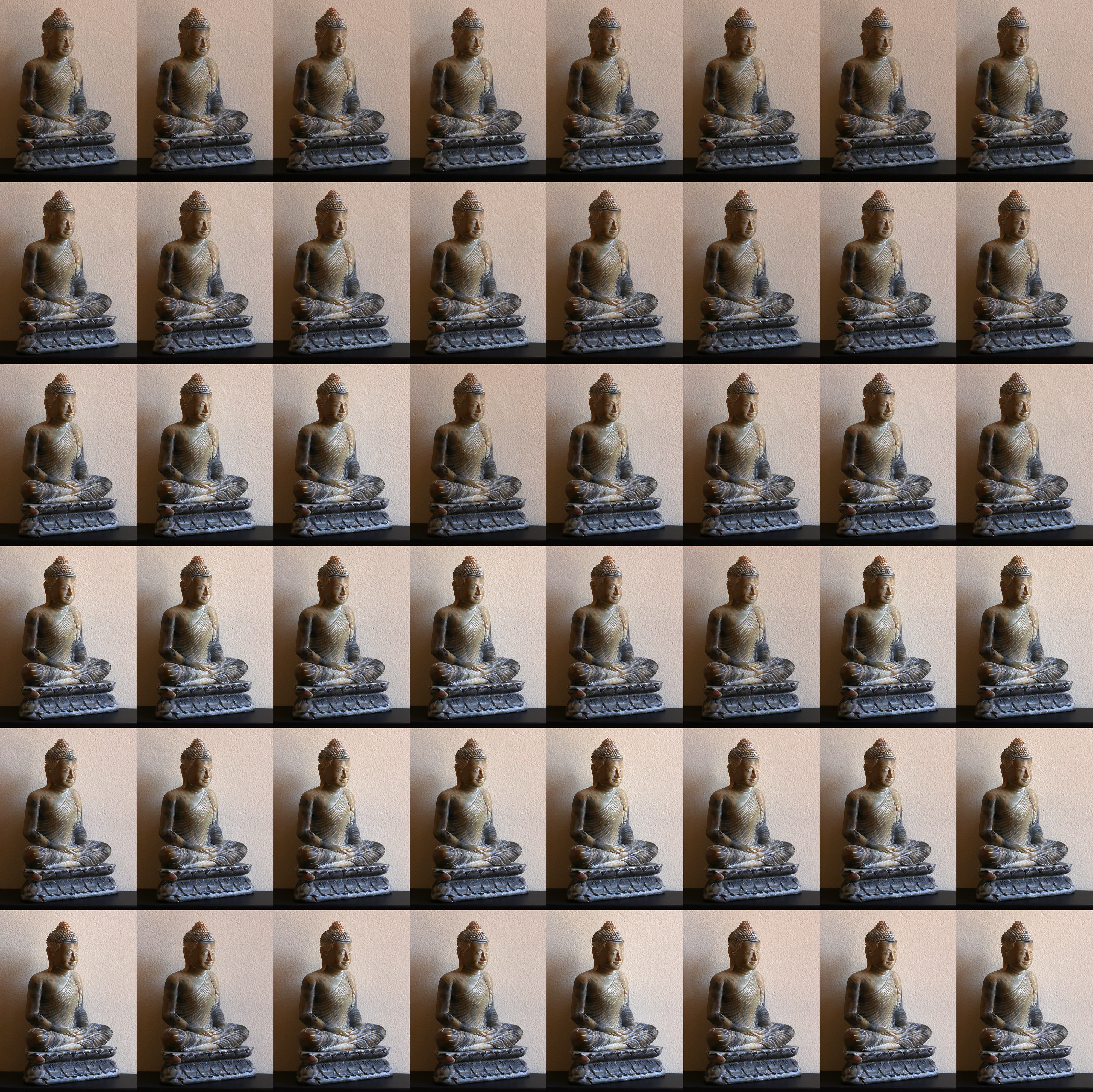 RGBD quilt Maximum negative parallax
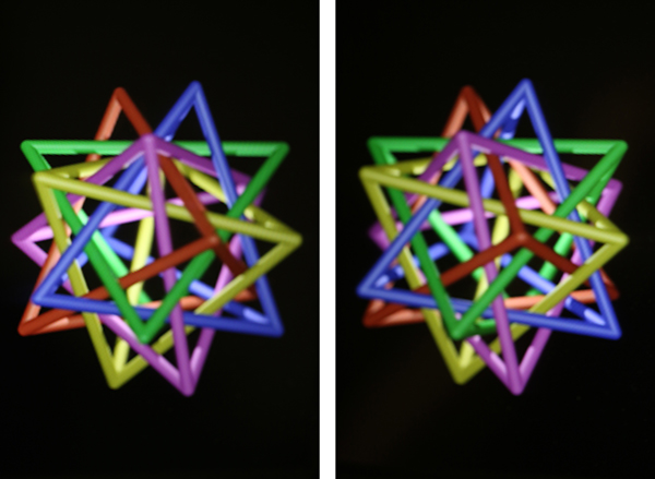
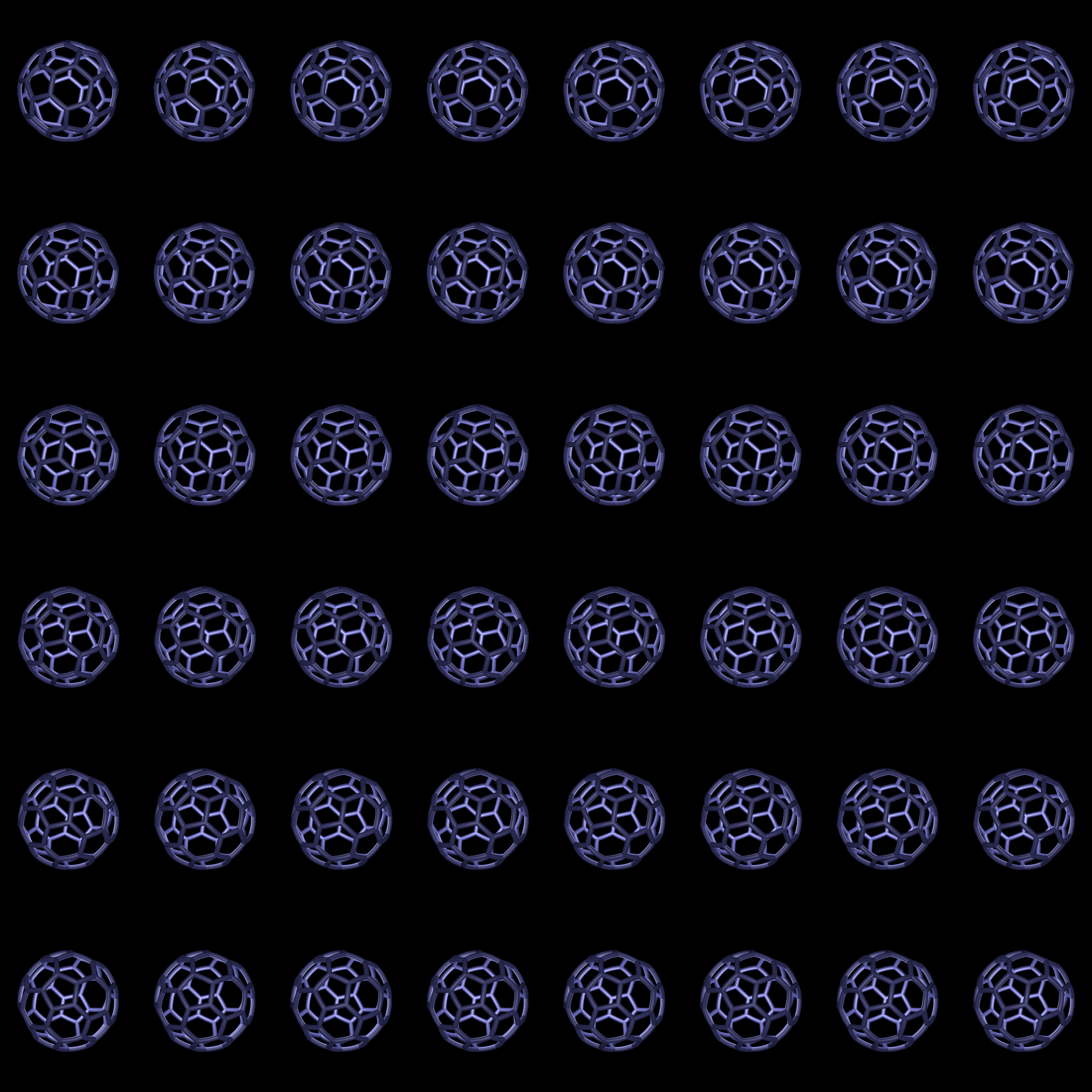
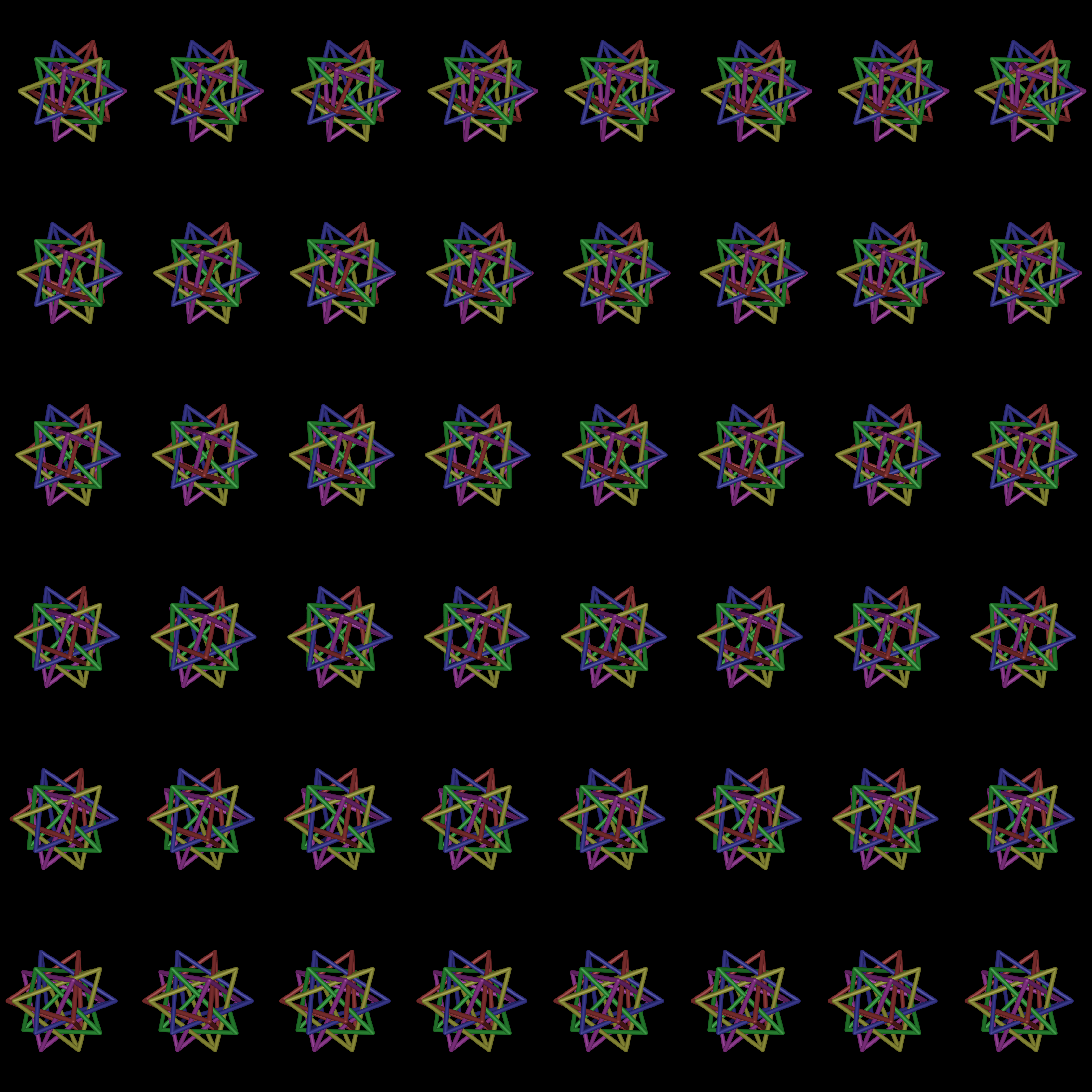
Any lenticular (and even general stereoscopic) display has a limitation on how far they can make objects appear in front of the display plane. It is common to construct the model volume in such a way that illustrates the constraints on object placement. It is particularly important for objects in front of the display plane (negative parallax) not to cut the frame of the display. Doing so produces a conflict between the virtual 3D position of the object and the physical 3D position of the framing, generally resulting in loss of depth perception. Since one is ideally modelling in Portrait display units, one can precisely predict the degree of positive and negative parallax. The following is a model positioned such that the closest star point is 40mm in front of the display screen. While a little subjective, if one is positioned at the modelled distance (500mm) then it is believably 40mm in front of the back plane, or 20mm in front of the Portrait framing. 
Four quilts are provided where the closest object is at the display plane, the rest of the obj is entirely behind the plane (timestar_0.png), 20mm in front of the display plane (timestar_20.png), 40mm in front of the display plane (timestar_40.png) and finally 60mm in front of the display plane (timestar_60.png). The 60mm case is generally considered too far, the closest parts of the model are becoming "soft". The following movie is an example that brings an object from the display depth to 40mm in front: timestarmovie.mp4. |
