Creating unwrapped icosahedral mapsWritten by Paul BourkeSeptember 2020
The source code implementing the projections below is only available on request for a small fee. It includes a demo application and an invitation to convert an image of your choice to verify the code does what you seek. For more information please contact the author.
The concept of a projection plane in a perspective projection can be extended to a projection sphere when capturing a 360x180 degree image. The position on the sphere that an object in the world is projected to is determine by the intersection of a straight line with the sphere from the camera position to the world object. The problem of representing such an image on a flat plane without apparent distortion is well known and is historically the subject of cartography. The most common method is the equirectangular projection which is just a mapping with longitude and latitude being the two 2D axes. This projection has only one cut (left and right edge) but the appearance of the scene is stretched towards the top and bottom edge of the projection. The ultimate stretching occurs at the north and south pole were a single vector into the scene is stretched across the entire top and bottom edge. 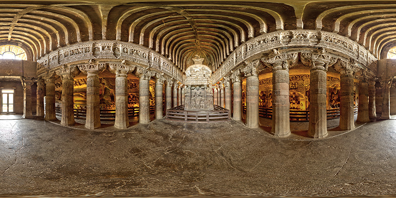
Another popular representation is the so called cubemap. In this case the projection sphere is mapped onto the 6 faces of a cube (the projection planes), each face being a 90 degree by 90 degree perspective projection. The extreme stretching of the equirectangular is now reduced to modest stretching towards the edges of the perspective projection, the price to be paid is that there are multiple cuts, 7 in total. The perspective stretching can be further reduced by employing the equiangular cubemap. 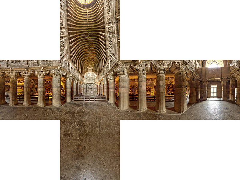
While each face of an unfolded cubic projection is a familiar perspective projection, and the front-top-bottom faces of the unfolded cube make sense, the relationship between the left-right-back faces and the top and bottom faces is by no means clear. There is nothing special about projecting the projection sphere onto a cube, the main attraction being that the sides are square and can therefore each be efficiently represented by six square images. But there is nothing stopping one from projecting onto any closed (preferably convex so a single valued function of longitude and latitude) polyhedron and then unwrapping that so it lies on a plane. In the following an icosahedron is used, it has 20 triangular faces and 12 vertices, compared to a cube which has 6 rectangular faces and 8 vertices. 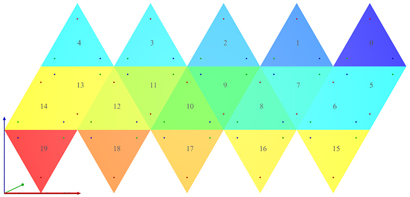
To get a sense of what this looks like consider the following equirectangular projection showing lines of longitude and latitude. 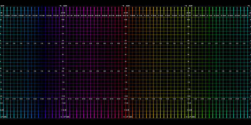
The corresponding unfolded icosahedron projection is shown below. 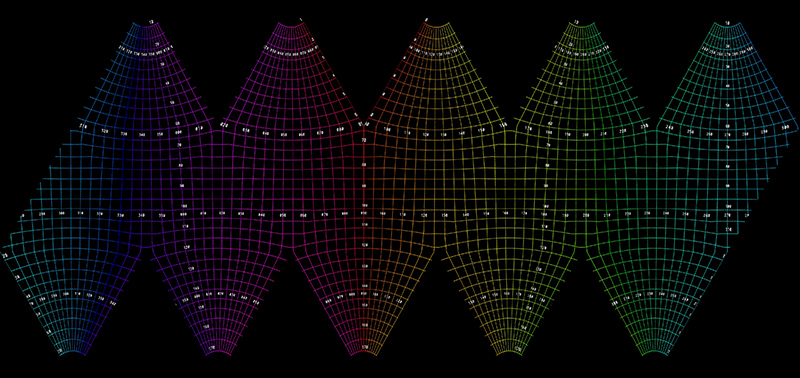
Another example using the same equirectangular that was used for the unfolded cube above is shown below. 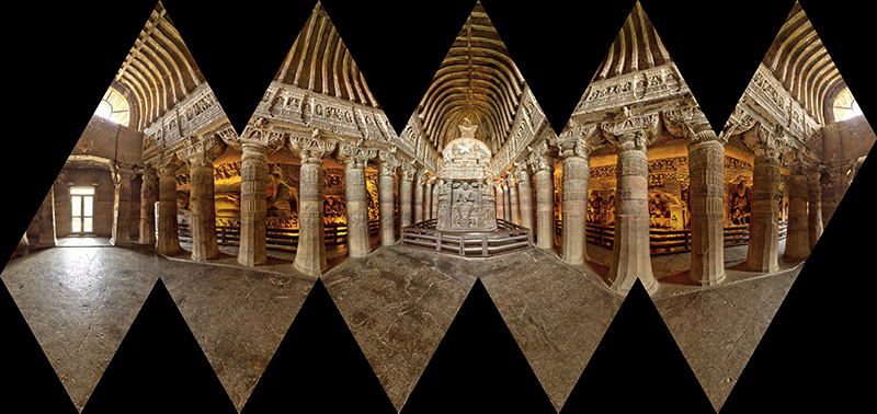
Each triangle of the icosahedron is of base width 1 and height sqrt(3)/2. There are 5.5 triangles horizontally and 3 triangles vertically so the aspect ratio of the image is 5.5/(1.5*sqrt(3)) = 2.11695. 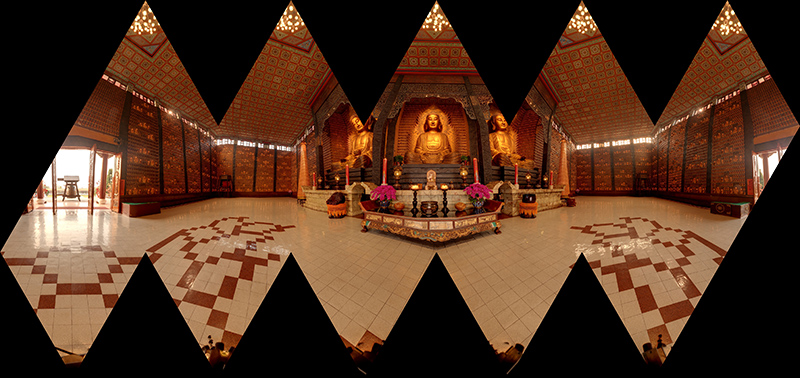
While the above have the triangular faces of the icosahedron intact, it does lead to an asymmetric layout. An alternative is to split two of the faces for the layout shown below. Aspect ratio is now 5/(1.5*sqrt(3)) = 1.9245 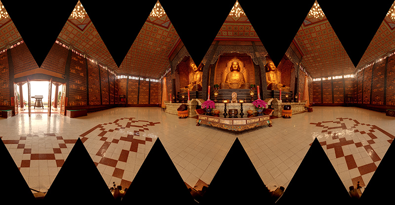
There are some advantages of using this unfolded icosahedral mapping.
Software has been developed that transforms an equirectangular into the two unwrapped icosahedral formats shown above. It is a simple command line utility, usage string is given below. It allows the output image size to be adjusted (-w) and rotation of the equirectangular with respect to the icosahedron (-x,-y,-z). It performs simple supersampling antialiasing (-a) and optionally creates remap filters (-f) for ffmpeg to facilitate the conversion of movies, removing the need to extract frame first, process and then rebuild the movie. Usage: sphere2icosa [options] sphericalimagename Options -d Enable debug mode, default: off -a n Level of antialising, default: 2 -w n Output image width, default: 4096 -f Create ffmpeg remap filter pgm files, default: off -s Create a symmetric unfolding, default: off -x n Tilt angle (degrees), default: 0 -y n Roll angle (degrees), default: 0 -z n Pan angle (degrees), default: 0 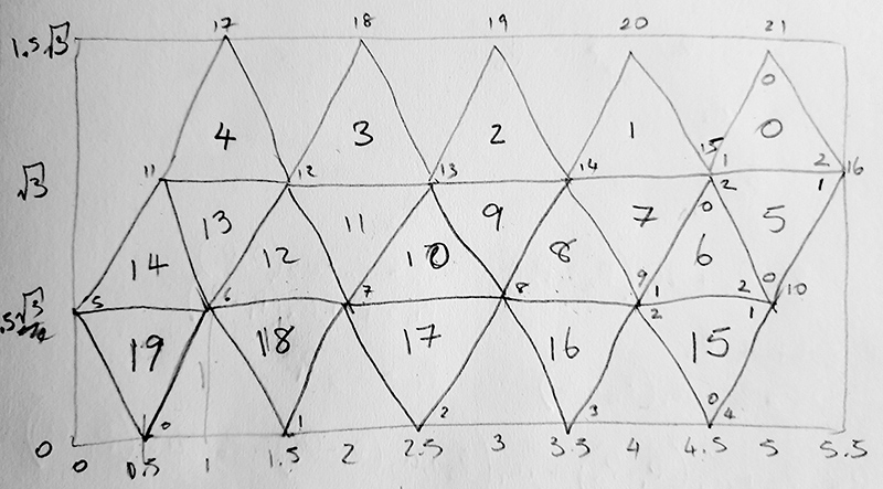
The mapping involves finding the best pixel in the equirectangular for each pixel in the output image. The triangular face containing each pixel is determined followed by the two triangular coordinates u1 and u2, this is simple matrix solution as shown below. These two coordinates are then used to index the matching 3D icosahedron triangle defining a vector in 3D. From this, one determines the longitude and latitude and therefore the pixel value in the input image. Of course all this is done as continuous points rather than pixels in order to implement the supersampling antialising. 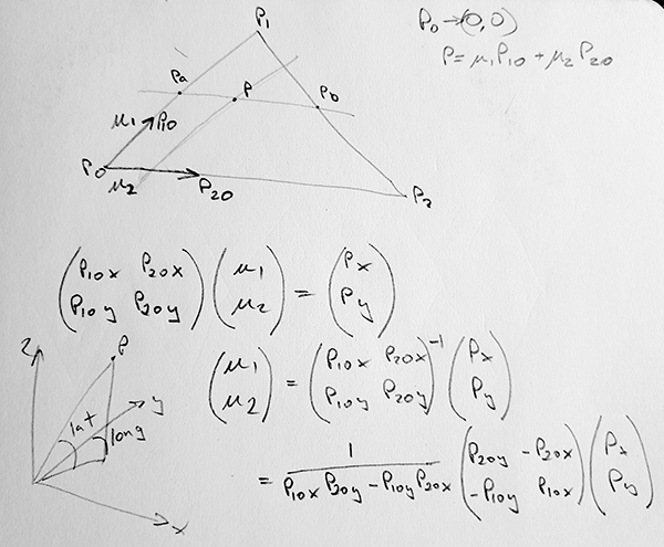
The three projections discussed here are illustrated below in 3D. Please note that if the camera were at the center of each one, and only ambient light were used then the internal views would all be identical. 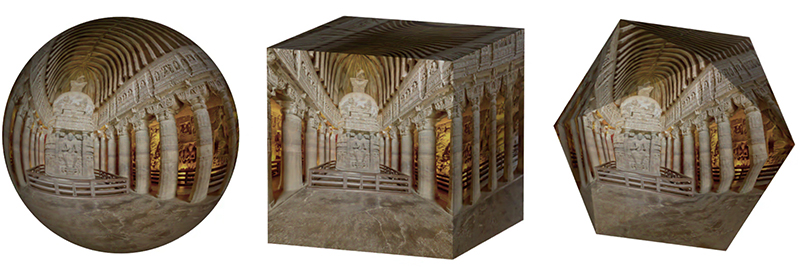
Each face in the versions above is a single triangular projection plane. As such, adjacent faces are different plane and can give a dog-leg style effect for straight lines that cross the boundary between two faces. This effect can be reduced by tessellating each triangular face. This is most conveniently done by repeatedly splitting each face into 4 triangles by bisecting each edge. 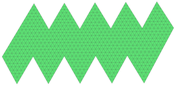
Some of the visual artefacts in the earlier versions have been removed. 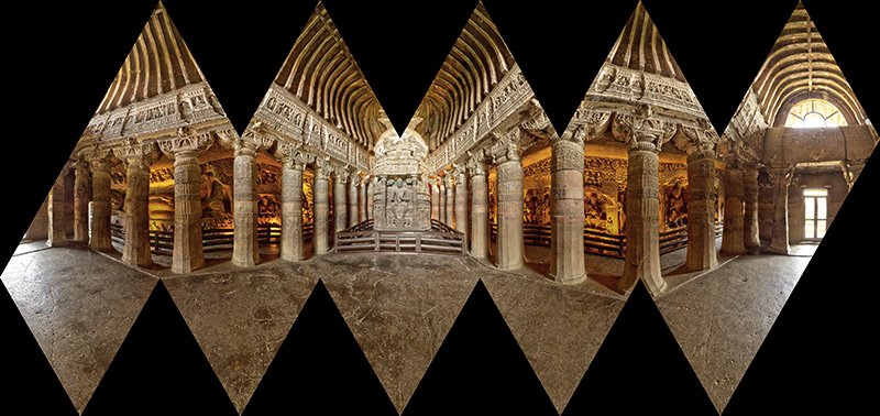
For a little history, the unfolding of the icosahedron and polyhedra in general is attributed to Albrecht Dürer (1471-1528), the following from one of his publications. 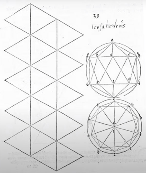
Creating dodecahedral mapsWritten by Paul BourkeSeptember 2020
The following is similar although there are some important differences. Here, instead of creating a single texture map, a separate texture map is created for each pentagonal face of the dodecahedron. When creating the OBJ file each face is created separately as 5 triangular faces with the correct texture coordinates. 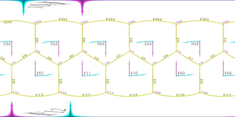
The other difference is that unlike the icosahedral map which forms a relatively efficient coverage on a rectangular image, the dodecahedron does not "unwrap" without large gaps and discontinuities. 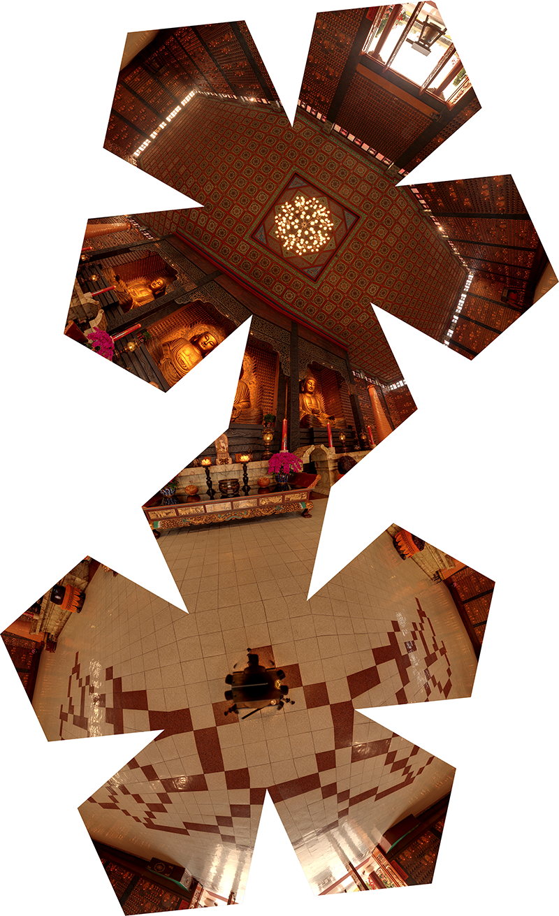
Usage: sphere2dodec [options] spherefilename
Options
   -w n   Image width (and height), default: 2048
   -a n   Degree of antialiasing, default: 2
   -c     Crop to pentagon, default: disabled
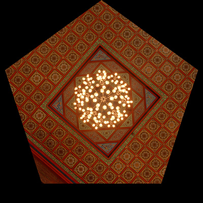
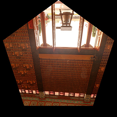
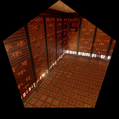
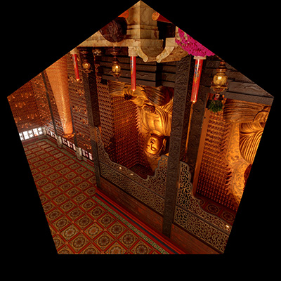
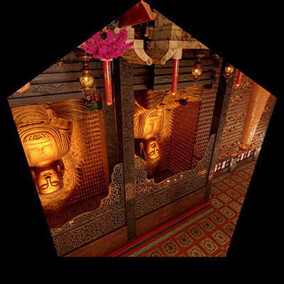
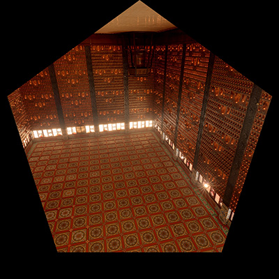
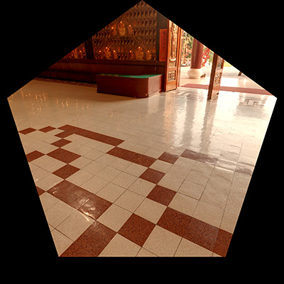
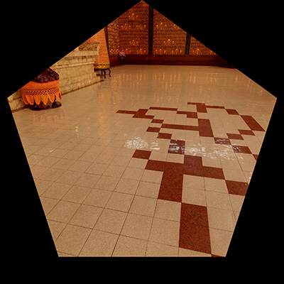
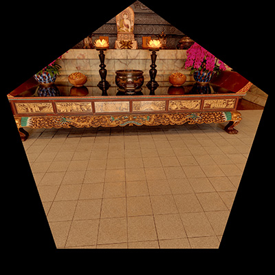
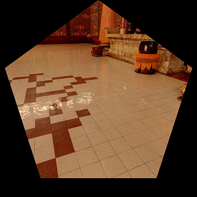
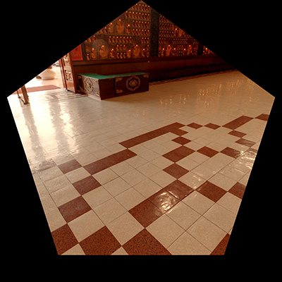
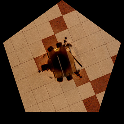
The 12 pentagonal texture maps are shown below.
|
