GoPro MAX 360 Action Cam movie layout/formatWritten by Paul BourkeSupported by Trek View September 2021 See the similar but simpler YouTube format
The following documents the 360 image layout the GoPro MAX camera uses to deliver most of its movie content. Instead of providing the standard equirectangular format, it computes the 6 cube maps and lays them out in two strips, each strip contains 3 cube map faces. These faces are arranged in a similar way to the YouTube layout, further details here. However, 4 of the faces (left, down, right, top) have not had the two contributing fisheyes stitched. Rather there is an overlap zone that needs to be blended together before one can do anything useful with the images. The cube maps are encoded as EAC (Equi-Angle Cubemap), see further details here. Personal statement: It is the view of the author that this approach is extremely unhelpful. While in theory the idea of using cubemaps is a reasonable one, and EAC is a better mapping, any improvement in storage pixel efficiency is totally negated by the lossy compression used. It would be vastly better to just provide the standard equirectangular images which would then fit nicely into almost all workflows. Doubly objectionable is the EAC maps are not even complete, that is, 4 of the faces have not even been stitched. Quite a shameful approach by GoPro that can only be explained by them having some desire to obfuscate matters and make life more difficult than it needs to be for users of the camera. There are two layout templates depending on the frame size being recorded which is turn are related to the frame rate of the recording. Note that these two layouts do not have the same aspect ratio so need to be treated individually. Layout and pixel dimensions for the 5.6K modes, 24fps and 30fps, and timelapse is illustrated below. 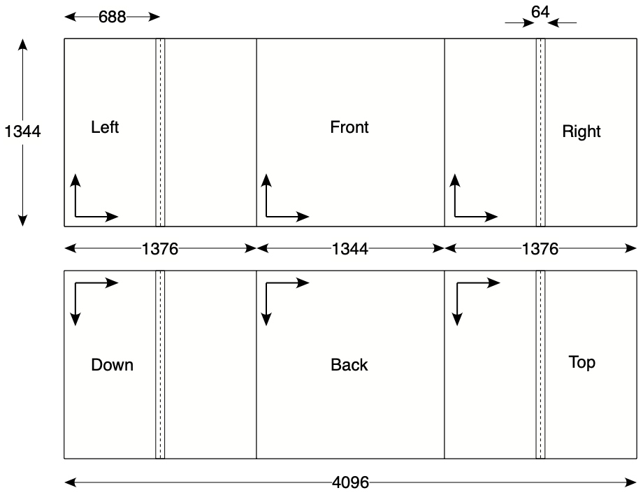
The narrow strips on the left, right, down and top faces of the cube are the overlapping zones from the fisheyes. So, there are 32 pixels on each side of the central lines of those faces that need to be overlaid and blended together. Layout and pixel dimensions for the 3K modes, 60fps. 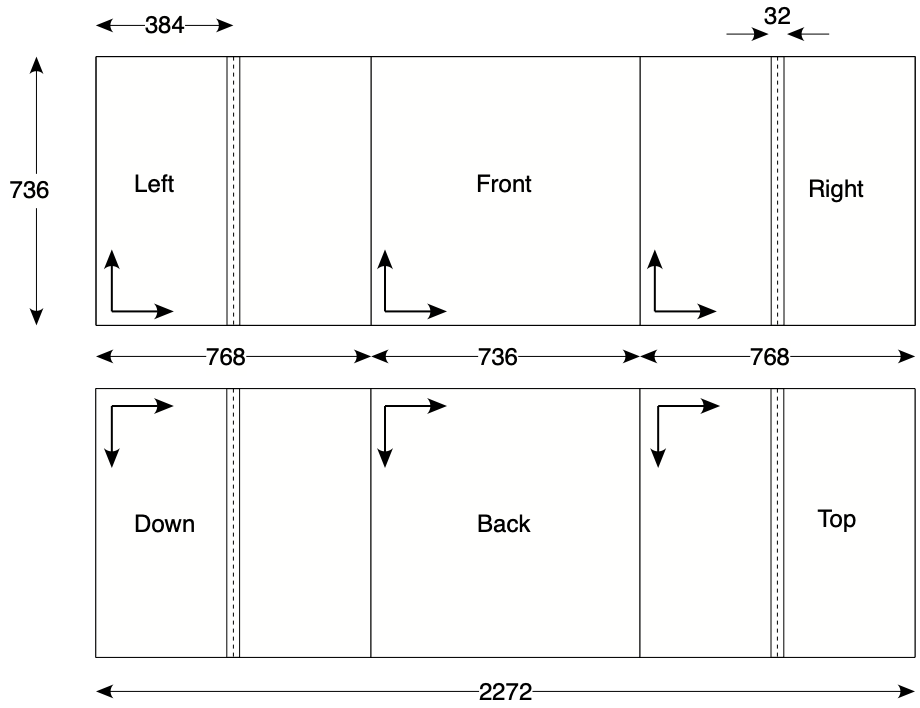
The movies are stored as two different video tracks within the same movie container. The tracks are 0 and 5 for the video modes, tracks 0 and 4 are used for the timelapse modes. The use of multiple video tracks is largely unsupported by video editing software, but can be readily dealt with using ffmpeg. To further ignore common conventions, the movies are not labelled with the usual extension ".mp4" but rather ".360". Extracting the frames from the tracks using ffmpeg might be performed as follows. ffmpeg -i GS000000.360 -map 0:0 -q:v 1 -qmin 1 track0/img%d.jpg ffmpeg -i GS000000.360 -map 0:5 -q:v 1 -qmin 1 track5/img%d.jpg Or if one wants just one frame every second. ffmpeg -i GS000000.360 -map 0:0 -r 1 track0/img%d.jpg -map 0:5 -r 1 track5/img%d.jpg Or extract the two tracks to two separate movies. ffmpeg -i GS000000.360 -map 0:0 -vcodec copy -acodec copy channel0.mp4 ffmpeg -i GS000000.360 -map 0:5 -vcodec copy -acodec copy channel5.mp4
Armed with the above information it isn't difficult to extract the cube map faces, fix up the overlap on the 4 faces that require it, and export the plain cube maps or form an equirectangular. Two implementations have been created, the first uses Vuo to extract the cube faces, it uses a simple shader to do the blending across the overlap region. Optionally a subsequent shader could be used to create the equirectangular, in Vuo this can all be performed in realtime. The Vuo project that extracts and processes the cube map faces is shown below, the reader should be able to conform the dimensions for the various parts matches those shown in the first layout described above. 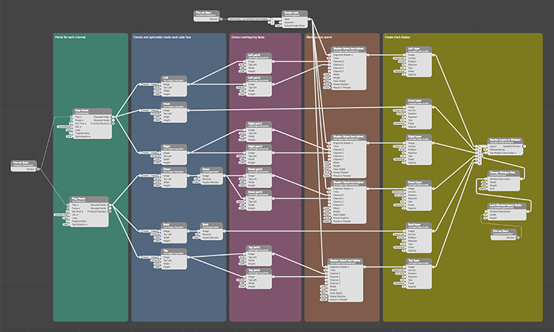
The second implementation is a command line utility that converts a frame pair. This can be scripted to process frames from the movies, it also gives higher resolution results when applied to the timelapse images. The usage string for the command line utility is as follows. Usage: MAX2sphere [options] track0filename track5filename Options -w n sets the output image width, default: 4096 -a n sets antialiasing level, default = 2 -o s specify the output filename, default is based on track0 name -d enable debug mode, default: off Example 1 - test images
The following two frames correspond to the 5.6K image layout and have been designed to check cube map orientation and blending across the overlap zones during the software development process. 

Layout of the cube mape faces with blending applied to the overlap regions. 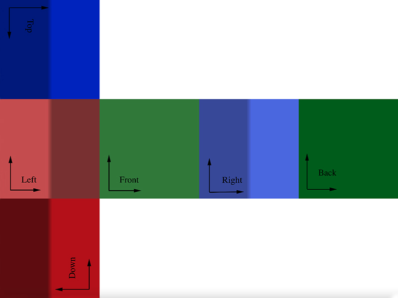
Resulting equirectangular image where the blending across the overlap zones can be observed and the convention for the position and orientation of the top and down frames. The coverage of the two fisheye lenses is evident here. 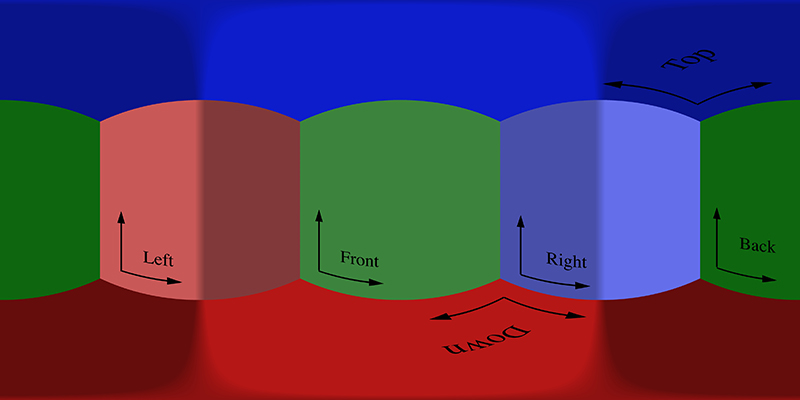
Example 2
Sample frames from track 0 and 5. The overlap zones can be identifies on the left, right, top and down sections of the cube maps. Only the front and back sections are "pure". 

Layout of the cube mape faces, blending across overlap applied but still EAC. The EAC correction is performed when transforming to equirectangular. 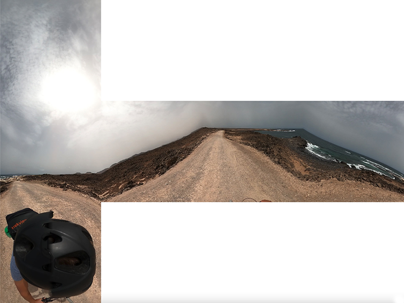
Resulting equirectangular image. 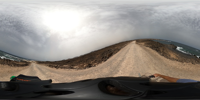
Example 3


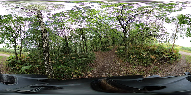
|