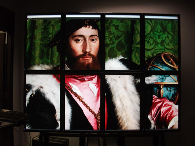
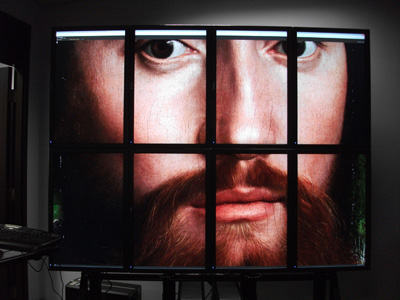
Tiled DisplaysWritten by Paul BourkeSeptember 2009, Update: May 2013
The following discusses the relative merits of tiling conventional displays in order to achieve a high resolution display. The main use of such displays in visualisation is to be able to see detail as well as the big picture. On a lower resolution display one is required to zoom in to see the detail at which point the context is lost. Similarly, when the whole image is visible the detail is smaller than a single pixel and thus lost. An intentional design criteria in the installation discussed here was the use of a single computer in order to maximise the support across commercially available software, at the cost of performance compared to using a cluster. This can be partly justified by the expectation of increased graphics performance in time. 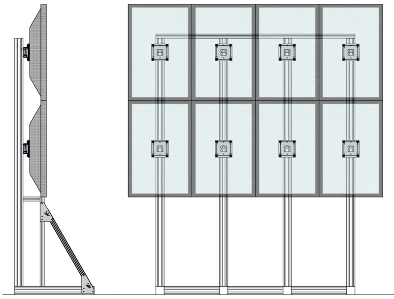
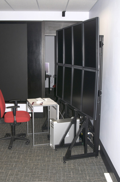
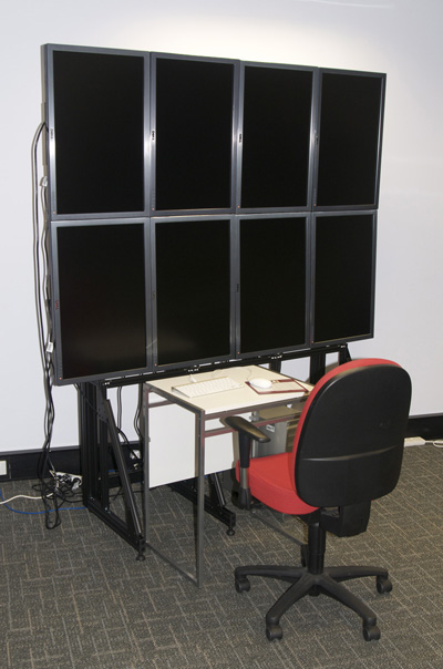
The design is based upon the Apple or DELL 30 inch displays, each one 2560x1600 pixel resolution, the highest on the market at the time. The displays are from the same factory, unfortunately the frame is about the same thickness for both and cannot readily be removed. The DELL displays were chosen simply because of the dark frame vs the lighter frame for the Apple version. The maximum number of dual pipe dual link DVI graphics cards that could be installed in the machine of choice (Apple Mac Pro) was 4, in other words 8 displays. The 2x4 arrangement with the panels on their sides gives the most convenient aspect ratio of 5:4 (6400 x 5120).
While the gaps between each frame is an obvious disadvantage, in order to achieve the raw pixel resolution it is more cost effective than using tiled data projectors. Not only is there the cost benefit but also the software complexity dealing with edge blending between tiled projector displays (assuming a seamless display is the target). It should be noted that these 30 inch monitors at 2560x1600 pixels have almost twice the pixels of a HD projector (2560x1600 compared to 1920x1080). 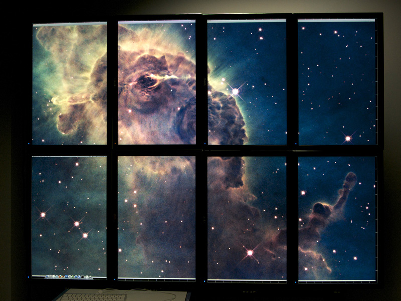
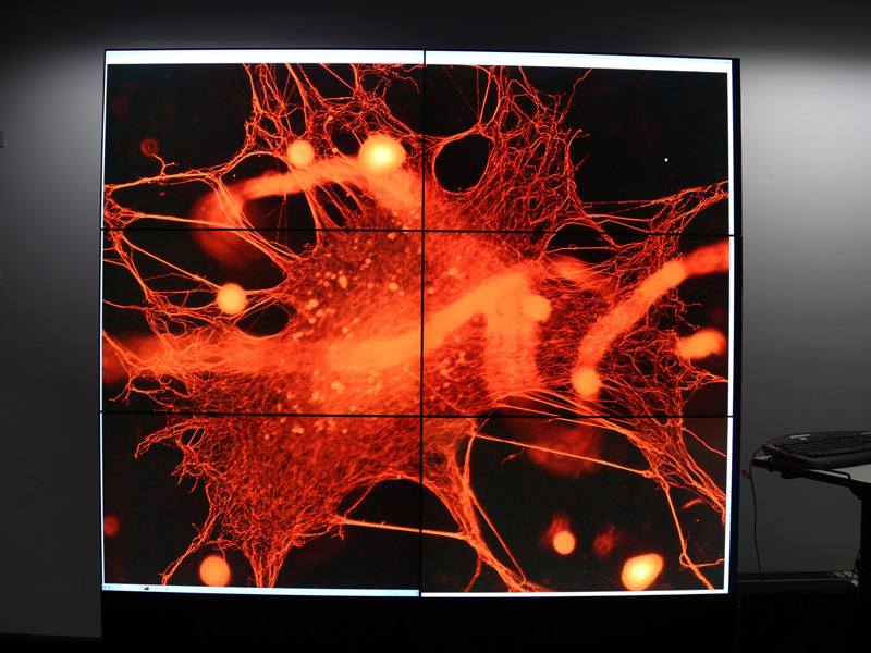
The colour depth of these displays would seem to be better than what one can achieve with data projectors, this includes the black levels. The first two images are fresh from the repaired Hubble Space Telescope, these first offerings at the time of writing were in the range of 3K and 4K square. The total resolution of the display is 4*1600 pixels horizontally by 2*2560 pixels vertically, a total of 6400 by 5120 (32MPixels). 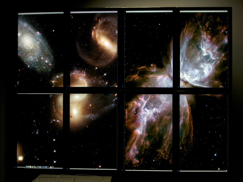
The following image is a high definition photograph of the Boolardy station in West Australia and the site of the ASKAP (Australia Square Kilometer Array Pathfinder), the site of the proposed SKA. The image is 32,000 by 32,000 pixels. 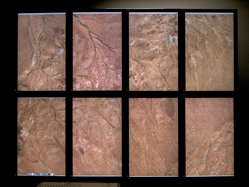
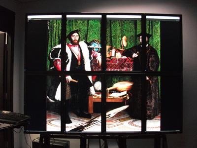
An example of a tiling of high resolution images, courtesy of Florian Fusseis. Notice the second display from the top left is a different colour, this is due to it being a replacement screen where the displays were originally a running sequence of serial numbers. Colour space adjustments on the panels have subsequently been made to create consistent colours across all panels. 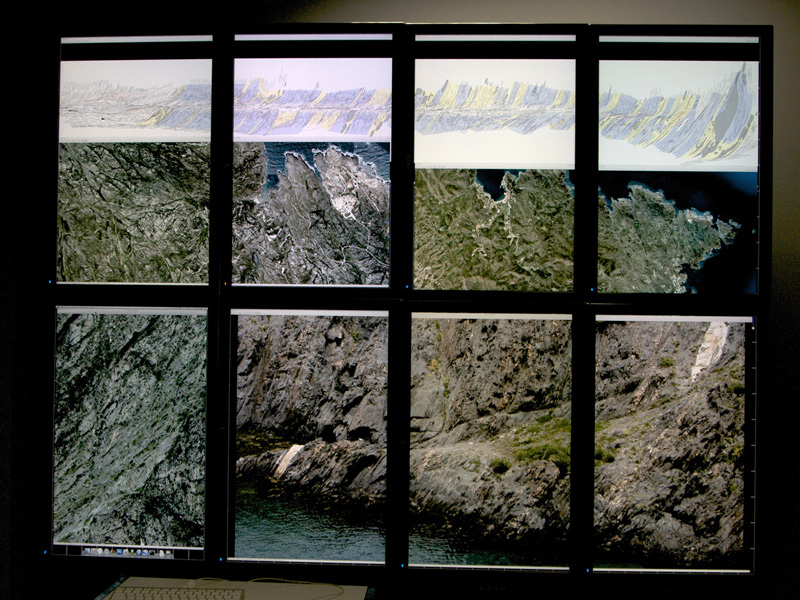
A further example from the recent high resolution images from the Hubble Space Telescope. 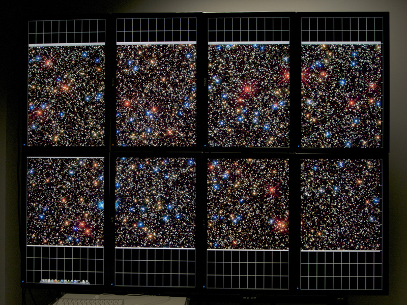
The above were all using standard Mac applications (eg: PhotoShop and Preview), the main issue with this is the inability to take account of the gaps between the displays giving quite an unnatural sensation as one tracks content between displays. A particularly elegant way to deal with this is the Quartz Visualiser. The following example uses a Quartz Composer composition to display the image, allow the user to scale, pan, and rotate. Quartz Visualiser then takes that are handles the image across the tiled display and automatically adjusts for a user specified interdisplay gap. While perhaps not evident here, the way the image disappears behind the frames between the display area results in a much more believable result, not surprising perhaps since we are accustomed to viewing scenery through frames windows. The only slight complication is that Quartz Visualiser ignores mouse and keyboard IO, this simply means a separate QC composition is created that runs on a separate computer and controls the translation, zooming, and rotation through a network patch. The two QC compositions are provided to give an idea of how this is achieved. 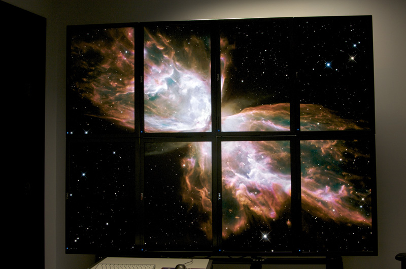
At the time of writing (Snow Leopard 10.6.1) seems to have a number of bugs when it comes to supporting this number of displays. Serious bugs such as the display preferences for arranging the displays runs very slowly and often fails to display the panels at all. 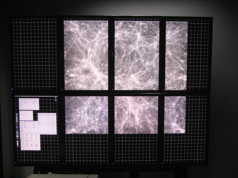
Application to interactive viewing of cosmological simulation data, 15 million points. Update, August 2010
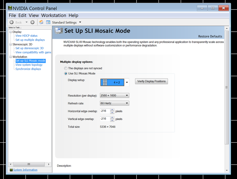
The display has been upgraded from a single Mac with 4 graphics cards to a single MSWindows (and Linux) box with a pair of nVidia Quadraplex units. These, in SLI mode present a single large canvas to any application. The result is a considerable increase in performance while retaining the desired ability to run any software. 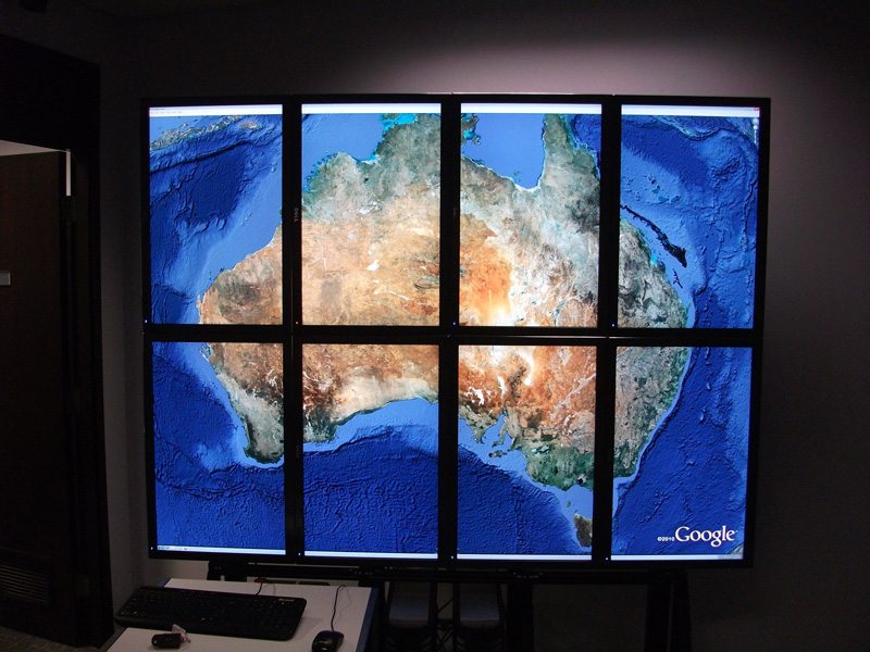
The nVidia drivers take care of the bezel width and in the latest version (at the time of writing) just started supporting portrait mode. 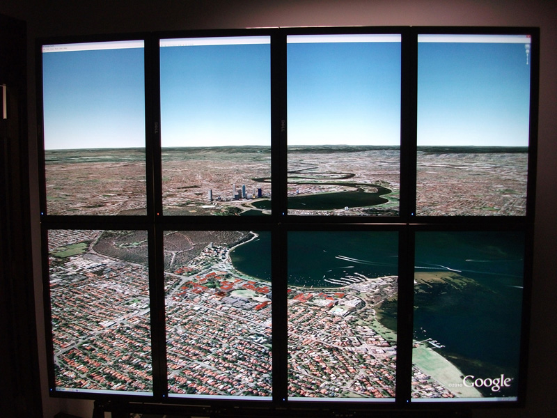
This is different to the Google "Liquid Galaxy" on a few points.
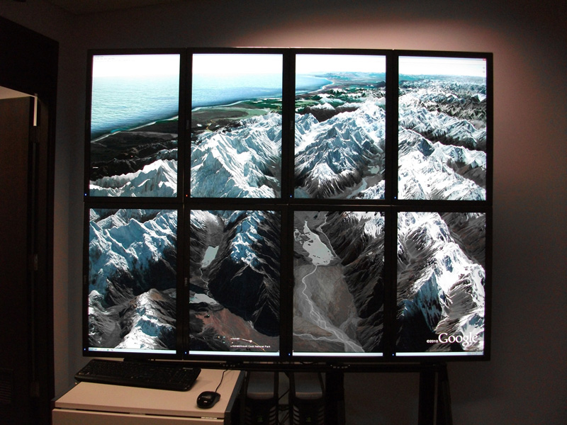 Configuration
At the time of writing (February 2011), the nVidia drivers leave a lot to be desired. They don't "naturally" support portrait mode, the work-around is set SLI as a 4x2 landscape and then switch to portrait in the MS display preferences. 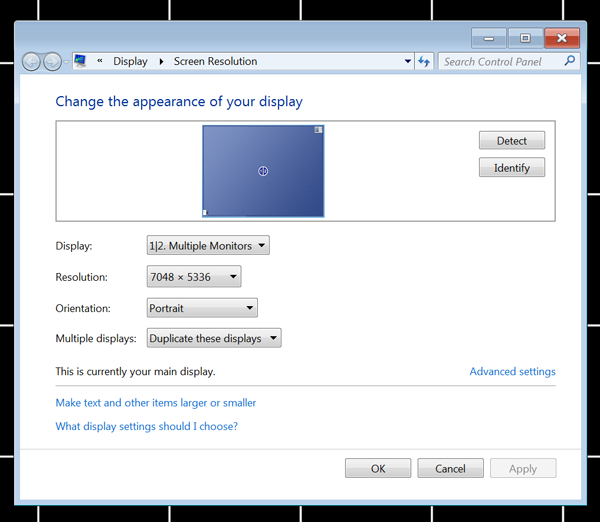
This display is made up from lower resolution (just HD, 1920x1080) panels, the obvious difference is the small size of the bezels. Rated at 5.5mm pixel to pixel, in reality it is more like 7mm. The panels used here are from Samsung, each 46 inches diagonal, that is just over 1m wide. The array comes ready to assemble in almost any desired configuration. 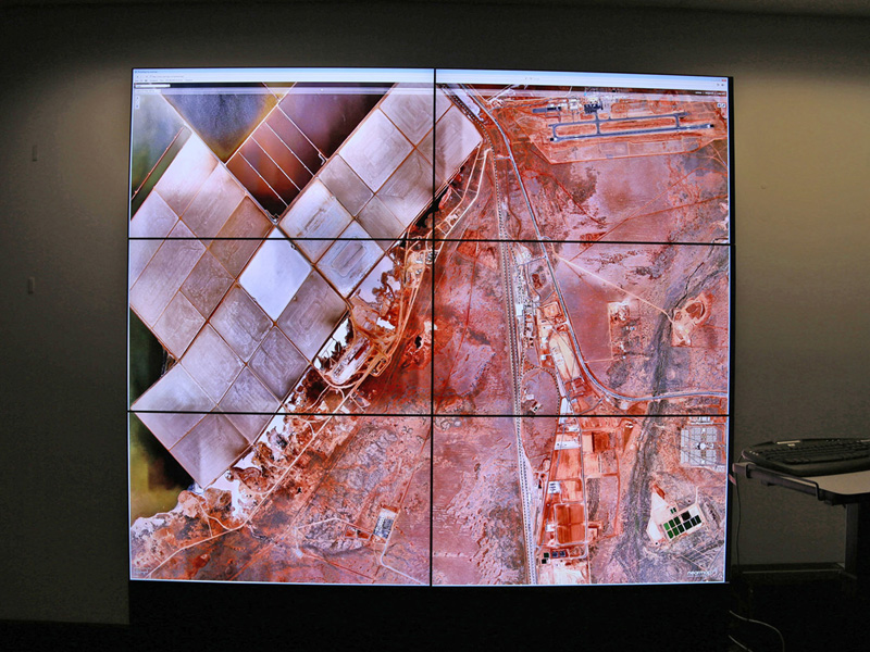
Sales pitch: "Such displays can be beneficial when studying high resolution datasets, typically images or high density 2D and 3D graphics. The large number of available pixels allows one to see more of the data thus reducing the need to pan and zoom. The larger physical scale of the display also facilitates collaborative use by more than one person, compared to a single small display." 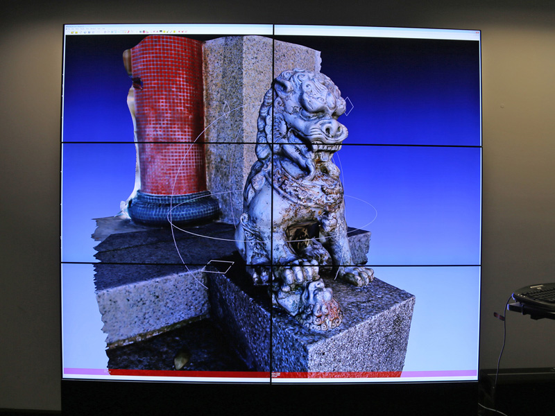
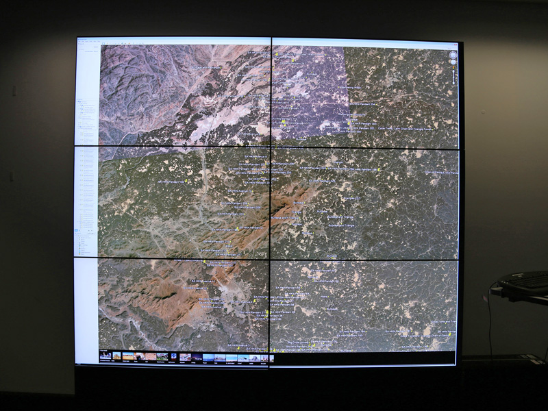
As before, this is driven by a single computer, in this case a FirePro W9000. The unique feature of this card are the 6 DisplayPort outputs allowing one to drive the 6 displays directly. Of course this installation is only about 12 MPixels, much less than the previous version. 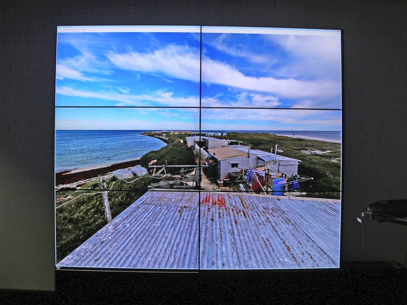
AMD control panel shown below, called the "Catalyst Pro Control Centre". Certainly a significantly more stable and elegant interface than the nVidia driver control panels. 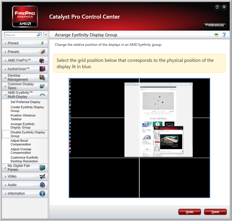
Display resolutionWritten by Paul BourkeMarch 2014
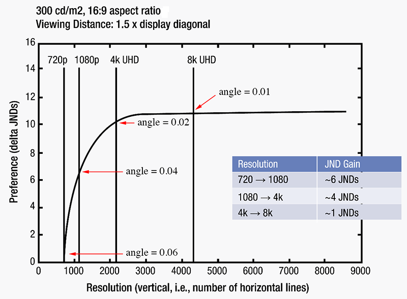
The following will present the relative resolution of different displays. A relatively straight forward exercise but as a frequently asked question it warrants some consideration. The first thing to realise is the perceived resolution is not just about the technical resolution of the display or projector. It also depends on the size of the display and the distance of the viewer. The best measure of the perceived resolution is the angle a pixel subtends at the eye, so for a device with a certain number of pixels the perceived resolution increases as the device becomes smaller or as the viewer get closer. In what follows it will be assumed the pixels are square, the vast majority of the cases these days, this allows us to only consider the horizontal angle a pixel subtends at the eye, the vertical angle will be the same. It should be noted that the discussion here assumes a perfect device displaying content with independent pixels, this is rarely the case (see later for degrading effects). If N is the number of horizontal pixels, W the physical width of the display or projected image, and D the distance the viewer is from the display, then the angle A in radians of a single pixel subtended at the eye is simply
The following table gives some representative subtended angles for commonly encountered display panels or projected images.
What might ask what the resolving power of the human eye is, there is not one definition. 20/20 vision is defined as the ability to resolve two points of light separated by a visual angle of 0.016 degrees. Alternatively the maximum angular resolution of the human eye at a distance of 1 km is typically 30 to 60cm, this gives an angular resolution of between 0.02 to 0.03 degrees. It should be noted that the above considerations relate to the idealised situation, in reality the actual perceived resolution of a digital image presentation can be less. Some factors reducing the effective resolution are listed below.
Planetariums domes
One might extend this to planetariums although in this case the true resolution is influenced by other things. In what follows it will be assumed that the rated dome projection is real where in fact it is not, for example the use of the words "4K" and "8k" to refer to dome resolution have no meaning in reality but are purely marketing terms. This is due to the following factors.
In the following table it is assumed that the observer is in the center of the dome and located at the spring line (the ideal viewing position). For viewers off center the angle a pixel subtends at the eye increases for the most distant side of the dome and decreases for the close side. Note that in the scenario discussed here the radius of the dome is not a factor, on a larger dome the pixels are larger but further away so the perceived resolution remains the same.
Comparative resolution of 360 video capture devices
Paul Bourke | |||||||||||||||||||||||||||||||||||||||||||||||||||||||||||||||||||||||||||||||||||||||||||||||||||||||||||||||||||||||||||||||||||||||||||||||||||||||||||||||||||||||||||||||||||||||||||||||||||||||||||||||||||||||||||||||||||||||||||||||||||||||||||||||||||||||||||||||||||||||||||||||||||||||||||||||
| Estimated resolution | |||||
| Device | N | 2m | 5m | 20m | Comments |
| LadyBug-3 | 5400 | 2 mm | 6 mm | 23 mm | 16 fps at this resolution. Spherical. |
| LadyBug-5 | 8000 | 1.5 mm | 4 mm | 16 mm | 10 fps at this resolution. Spherical. |
| H3Pro7HD (Kolor) | 8000 | 1.5 mm | 4 mm | 16 mm | 7 GoPro cameras mounted in portrait. Cylindrical. |
| H3Pro7 (Kolor) | 6000 | 2 mm | 5 mm | 21 mm | 7 GoPro cameras. Spherical. |
| Lucy (Kogeto) | 2000 | 6 mm | 16 mm | 63 mm | Example of camera based upon 1920 video. Cylindrical. |
| Joey (Kogeto) | 4000 | 3 mm | 8 mm | 31 mm | Not yet available at time of writing. Cylindrical. |
| Bublcam | 2500 | 5 mm | 13mm | 50 | Not yet available at time of writing. 4 x 720p camera at 30fps. Spherical. |
| Bublcam | 3600 | 3.5 mm | 8 mm | 35 mm | Not yet available at time of writing. 4 x 1920p camera at 15fps. Spherical. |
| Centrcam | 6900 | 1.8 mm | 4.5 mm | 18 mm | Not yet available at time of writing. Maximum 30fps. Cylindrical. |
Confounding factors
In the above it has been assumed that if a device can capture N pixels horizontally, then those pixels are "pure", this is never the case. Further degradation can occur and some sources are listed below.
Many of the camera solution do not result in a uniform resolution across the cylindrical or spherical projection. This is particularly true of single camera solutions based upon conical mirrors.
In the case of many commodity devices, while they may contain the same sensor as more expensive versions, there can be a poorer quality lens in front of the sensor. This generally means that pixels are no longer independent (they receive light over a wider region of the world) and generally an increase in chromatic error. This is particularly true of many of the mobile phone based options.
Different sensors have different levels of random noise, especially in low light.
Digital video capture is often limited by the bandwidth to the recording device. To maintain a recording resolution and frame rate the video is generally compressed with corresponding artefacts. The slower the recording device, the more compression and video degradation that occurs. Particularly so with SD storage medium in the GoPro, and others.
While the only scalable means of increasing the resolution is to use multiple cameras, this introduces potential resolution degradation across the overlap and blending zone. While there are multiple camera configurations, that with the use of mirrors, can create a single projection point, the majority have an offset projection point. For very fundamental reasons this means that a perfect stitch/blend across all depths is impossible.
Resolution of display technologies
Written by Paul BourkeJanuary 2007
The resolution of a digital display is a key component of the perceived quality. There are a number of factors that affect the resolution, such as: projector lens quality, interpixel leakage, surface properties, compression codes, geometry distortion, keystone, colour space, and so on. However one can calculate the upper quality possible by the display system by assuming a perfect system where the above have no degrading effect and considering just the pixel resolution. The figure of merit proposed is the angle a pixel subtends at the eye, convenient units for the scale of most current displays is arc seconds. This definition of resolution for some common devices is shown in the chart below, there is a bias/interest in displays the author has been involved in.
Comparison chart
| Display type | Projection resolution | Dimensions | Viewing distance | Resolution (arc seconds) |
| Apple 30" display | 2560x1600 | 30 inch diagonal | 600mm | 86 |
| Standard 17" display | 1280x1024 | 17 inch diagonal | 600mm | 92 |
| iPod video | 320x240 | 2.5 inch diagonal | 300mm | 109 |
| Flat screen projection (VROOM) | XGA (1024x768) projector | 2m wide | 2m | 201 |
| Flat screen projection | SXGA+ (1400x1050) projector | 2m wide | 2m | 149 |
| Flat screen projection | HD (1920x1080) projector | 2m wide | 2m | 109 |
| Dome | Full fisheye, XGA (1024x768) projector | * | Located at center | 539 |
| Dome | Full fisheye, SXGA+ (1400x1050) projector | * | Located at center | 395 |
| Dome | Truncated fisheye, SXGA+ (1400x1050) projector 75% coverage |
* | Located at center | 292 |
| Dome | Truncated fisheye, HD (1920x1080) projector 56% coverage |
* | Located at center | 218 |
| Dome | Spherical mirror** and HD (1920x1080) projector Full dome coverage and 2/3 of the pixels used |
* | Located at center | 309 |
| Dome | Spherical mirror** and HD (1920x1080) projector 80% dome coverage and 3/4 of the pixels used |
* | Located at center | 264 |
| Dome (planetarium) | 6 projectors, each SXGA+ (1400x1050) |
* | Located at center | 149 |
| Dome (planetarium) | 6 projectors, each HD (1920x1080) |
* | Located at center | 126 |
| Dome (planetarium) | Full dome using two SONY 4kx2k projectors | * | Located at center | 103 |
| Cylinder (AVIE) | 6 projectors, each SXGA+ (1400x1050) |
* | Located at center | 178 |
| Neptune | From Earth | 2.5 | ||
| Mars | From Earth | 20 |
Notes
- *For the dome and cylindrical environments the resolution is independent of the
size of the display assuming the observer is at the central sweet spot. As the dimensions of the
surface get larger the observer gets further away.
- For the multiple projector domes it is assumed that 2/3 of the display area of
each projector contributes to the final image. This does depend on the aspect ratio of
the projectors being used but is the upper limit for standard geometry corrected and
edge blended frames.
- **The spherical mirror projection does not result in equal size pixels
across the dome and it is possible to vary the dome coverage from the same as a truncated
fisheye to 100%. Some parts of the dome will be higher resolution, others lower.
In what follows the following symbols are used.
x y are the physical linear dimensions, width and height
r is the radius
w h are the pixel dimensions, width and height
d is the viewing distance
n is the number of projectors
A small angle approximation is used, namely tan(x) = x for small values of x.
Planar display, single projector
| resolution = sqrt[ | ------- | ] / d |
If the pixels are square and all are used then this reduces to
| resolution = | ------- |
Cylindrical display
Take the edge blend width in pixels into account for "w", the pixel width of each projector.
| resolution = [ | ------- | ] / d |
If the viewer is standing in the center this reduces to
| resolution = | ------- | |
Multiprojector Dome eg: planetarium
Assume each projector contributes 2/3 of its pixels to the final image.
| resolution = sqrt[ | ---------------- | ] / d |
If the viewer is located in the center then this reduces to
| resolution = sqrt[ | ---------------- | ] |
Dome projection with a single full fisheye
| resolution = sqrt[ | ---------- | ] / d |
For the observer at the center of the dome this reduces to
| resolution = | ---------- | |
Dome projection with a 3/4 truncated fisheye
| resolution = sqrt[ | ---------- | ] / d |
For the observer at the center of the dome this reduces to
| resolution = | ---------- | |
Dome projection using a single projector and spherical mirror
Assume p% of the pixels end up on the dome that is q% covered.
| resolution = sqrt[ | ----------- | ] / d |
For the observer at the center of the dome this reduces to
| resolution = | ----------- | |
