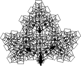
What is a fractal?
B. Mandelbrot
Mathematical Chaotic SystemsThe classic Mandelbrot below has been the image that has greatly popularised chaotic and fractal systems. The Mandelbrot set is created by a general technique where a function of the form zn+1 = f(zn) is used to create a series of a complex variable. In the case of the Mandelbrot the function is f(zn) = zn2 + zo. This series in generated for every initial point zo on some partition of the complex plane. To draw an image on a computer screen the point under consideration is coloured depending on the behaviour of the series which will act in one of the following ways: (a) decay to 0(b) tend to infinity (c) oscillate among a number of states (d) exhibits no discernible pattern
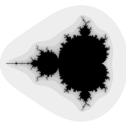
In the figure above, situation (a) occurs in the interior portion, (b) in the exterior, (c) and (d) near the boundary. The boundary of the set exhibits infinite detail and variation (the boundary will never appear smooth irrespective of the zoom factor), as well as self similarity. (Object pascal source code by Omar Awile) 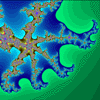
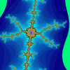
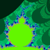
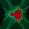
An example using the same technique but a different function is called "biomorphs" by C.A.Pickover. It uses the function f(zn) = sin(zn) + ez + c and gives rise to many biological looking creatures depending on the value of the constant "c". 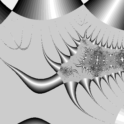
Julia Set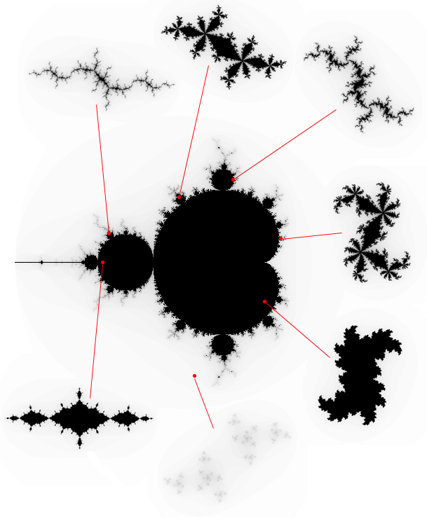
Quaternion Julia SetStrange AttractorsA second technique, often called "hopalong" after an article in Scientific American in 1986 by Barry Martin, is normally used to represent the strange attractor of a chaotic system, for example, the well known Julia set. In this case each coordinate generated by the series is drawn as a small point, ie: we hop-along from one point to the next. For an image on a plane the series is either an equation of a complex variable or else there are two interrelated equations, one for the x and one for the y coordinate. As an example consider the following function:
This series of x,y coordinates is specified by an initial point xo,yo and three constants a,b, and c. The following is an example where a=0.4, b=1, and c=0. 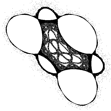
Interestingly for strange attractors the initial point does not matter (except for a few special cases), ie: all initial coordinates xo,yo result in the same image. In other words, the image shows the x,y pairs that can be generated by the series, any initial point will generate the same set of points although they will be generated in a different order. Another example attributed to Peter de Jong uses the two equations
This gives swirling tendrils that appear three dimensional, an example is shown below where a = -2.24, b = -0.65, c = 0.43, d = -2.43. 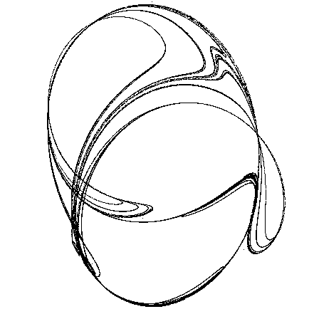
Lorenz, Rossler, Duffing AttractorNewton RaphsonThis technique is based on the Newton Raphson method of finding the solution (roots) to a polynomial equation of the form
The method generates a series where the n+1'th approximation to the solution is given by
where f'(zn) is the slope (first derivative) of f(z) evaluated at zn. To create a 2D image using this technique each point in a partition of the plane is used as initial guess, zo, to the solution. The point is coloured depending on which solution is found and/or how long it took to arrive at the solution. A simple example is an application of the above to find the three roots of the polynomial z*z*z - 1 = 0. The following shows the appearance of a small portion of the positive real and imaginary quadrant of the complex plane. A trademark of chaotic systems is that very similar initial conditions can give rise to very different behaviour. In the image shown there are points very close together one of which converges to the solution very fast and the other converges very slowly. 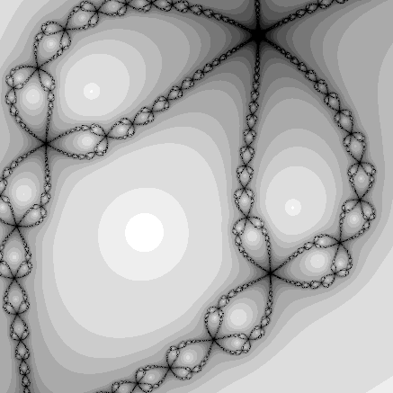
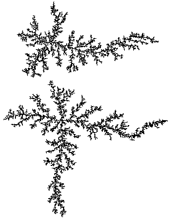
DLA - Diffusion Limited Aggregation
Fractal GeometryAlmost all geometric forms used for building man made objects belong to Euclidean geometry, they are comprised of lines, planes, rectangular volumes, arcs, cylinders, spheres, etc. These elements can be classified as belonging to an integer dimension, either 1, 2, or 3. This concept of dimension can be described both intuitively and mathematically. Intuitively we say that a line is one dimensional because it only takes 1 number to uniquely define any point on it. That one number could be the distance from the start of the line. This applies equally well to the circumference of a circle, a curve, or the boundary of any object. 
A plane is two dimensional since in order to uniquely define any point on its surface we require two numbers. There are many ways to arrange the definition of these two numbers but we normally create an orthogonal coordinate system. Other examples of two dimensional objects are the surface of a sphere or an arbitrary twisted plane. 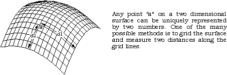
The volume of some solid object is 3 dimensional on the same basis as above, it takes three numbers to uniquely define any point within the object. 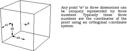
A more mathematical description of dimension is based on how the "size" of an object behaves as the linear dimension increases. In one dimension consider a line segment. If the linear dimension of the line segment is doubled then obviously the length (characteristic size) of the line has doubled. In two dimensions, ff the linear dimensions of a rectangle for example is doubled then the characteristic size, the area, increases by a factor of 4. In three dimensions if the linear dimension of a box are doubled then the volume increases by a factor of 8. This relationship between dimension D, linear scaling L and the resulting increase in size S can be generalised and written as
This is just telling us mathematically what we know from everyday experience. If we scale a two dimensional object for example then the area increases by the square of the scaling. If we scale a three dimensional object the volume increases by the cube of the scale factor. Rearranging the above gives an expression for dimension depending on how the size changes as a function of linear scaling, namely
In the examples above the value of D is an integer, either 1, 2, or 3, depending on the dimension of the geometry. This relationship holds for all Euclidean shapes. There are however many shapes which do not conform to the integer based idea of dimension given above in both the intuitive and mathematical descriptions. That is, there are objects which appear to be curves for example but which a point on the curve cannot be uniquely described with just one number. If the earlier scaling formulation for dimension is applied the formula does not yield an integer. There are shapes that lie in a plane but if they are linearly scaled by a factor L, the area does not increase by L squared but by some non integer amount. These geometries are called fractals! One of the simpler fractal shapes is the von Koch snowflake. The method of creating this shape is to repeatedly replace each line segment with the following 4 line segments. 
The process starts with a single line segment and continues for ever. The first few iterations of this procedure are shown below. 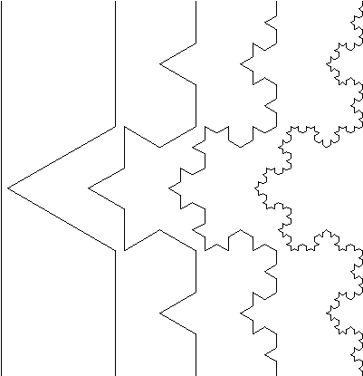
This demonstrates how a very simple generation rule for this shape can generate some unusual (fractal) properties. Unlike Euclidean shapes this object has detail at all levels. If one magnifies an Euclidean shape such as the circumference of a circle it becomes a different shape, namely a straight line. If we magnify this fractal more and more detail is uncovered, the detail is self similar or rather it is exactly self similar. Put another way, any magnified portion is identical to any other magnified portion. Note also that the "curve" on the right is not a fractal but only an approximation of one. This is no different from when one draws a circle, it is only an approximation to a perfect circle. At each iteration the length of the curve increases by a factor of 4/3. Thus the limiting curve is of infinite length and indeed the length between any two points of the curve is infinite. This curve manages to compress an infinite length into a finite area of the plane without intersecting itself! Considering the intuitive notion of 1 dimensional shapes, although this object appears to be a curve with one starting point and one end point, it is not possible to uniquely specify any position along the curve with one number as we expect to be able to do with Euclidean curves which are 1 dimensional. Although the method of creating this curve is straightforward, there is no algebraic formula the describes the points on the curve. Some of the major differences between fractal and Euclidean geometry are outlined in the following table. 
Firstly the recognition of fractal is very modern, they have only formally been studied in the last 10 years compared to Euclidean geometry which goes back over 2000 years. Secondly whereas Euclidean shapes normally have a few characteristic sizes or length scales (eg: the radius of a circle or the length of of a side of a cube) fractals have so characteristic sizes. Fractal shapes are self similar and independent of size or scaling. Third, Euclidean geometry provides a good description of man made objects whereas fractals are required for a representation of naturally occurring geometries. It is likely that this limitation of our traditional language of shape is responsible for the sticking difference between mass produced objects and natural shapes. Finally, Euclidean geometries are defined by algebraic formulae, for example
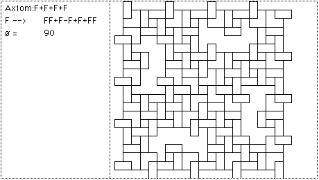
defines a sphere. Fractals are normally the result of a iterative or recursive construction or algorithm. Fractal LandscapesL-SystemsThe following is based on L-Systems as described in "Lecture Notes in Biomathematics" by Przemyslaw Prusinkiewcz and James Hanan. A brief description of an 0L system will be presented here but for a more complete description the user should consult the literature. Simple-minded example of 0L systemA string of characters (symbols) is rewritten on each iteration according to some replacement rules. Consider an initial string (axiom) and a rewriting rule
After one iteration the following string would result
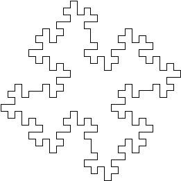
For the next iteration the same rule is applied but now to the string resulting from the last iteration F+ F-F-FF+ F+ F-F+ F+ F-F-FF+ F+ F-F-F+ F-F-FF+ F+ F-F-F+ F-F-FF+ F+ F-FF+ F-F-FF+ F+ F-F+ F+ F-F-FF+ F+ F-F+ F+ F-F-FF+ F+ F-F-F+ F-F-FF+ F+ F-F+ F+ F-F-FF+ F+ F-F+ F+ F-F-FF+ F+ F-F-F+ F-F-FF+ F+ F-F-F+ F-F-FF+ F+ F-FF+ F-F-FF+ F+ F-F+ F+ F-F-FF+ F+ F-F+ F+ F-F-FF+ F+ F-F-F+ F-F-FF+ F+ F-F+ F+ F-F-FF+ F+ F-F+ F+ F-F-FF+ F+ F-F-F+ F-F-FF+ F+ F-F-F+ F-F-FF+ F+ F-FF+ F-F-FF+ F+ F-F+ F+ F-F-FF+ F+ F-F+ F+ F-F-FF+ F+ F-F-F+ F-F-FF+ F+ F-F+ F+ F-F-FF+ F+ F-F+ F+ F-F-FF+ F+ F-F-F+ F-F-FF+ F+ F-F-F+ F-F-FF+ F+ F-FF+ F-F-FF+ F+ F-F+ F+ F-F-FF+ F+ F-F+ F+ F-F-FF+ F+ F-F-F+ F-F-FF+ F+ F-F Some symbols are now given a graphical meaning, for example, F means move forward drawing a line, + means turn right by some predefined angle (90 degrees in this case), - means turn left. Using these symbols the initial string F+F+F+F is just a rectangle (ø = 90). The replacement rule F --> F+F-F-FF+F+F-F replaces each forward movement by the following figure 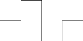 The first iteration interpreted graphically is
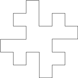 The next iteration interpreted graphically is:
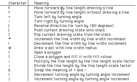
 The following characters have a geometric interpretation.
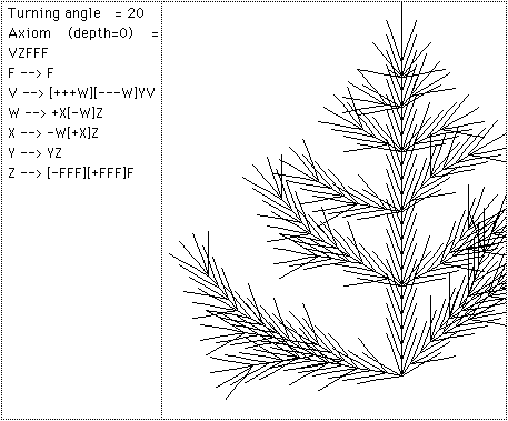
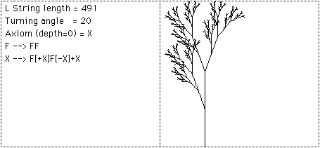
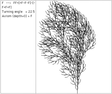
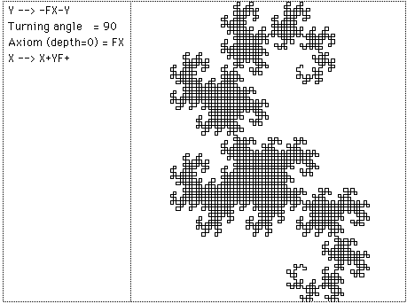
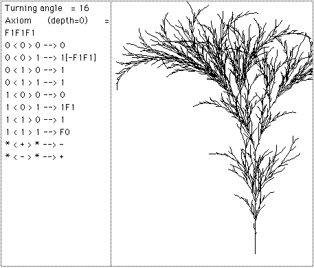
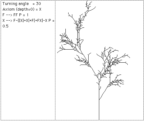
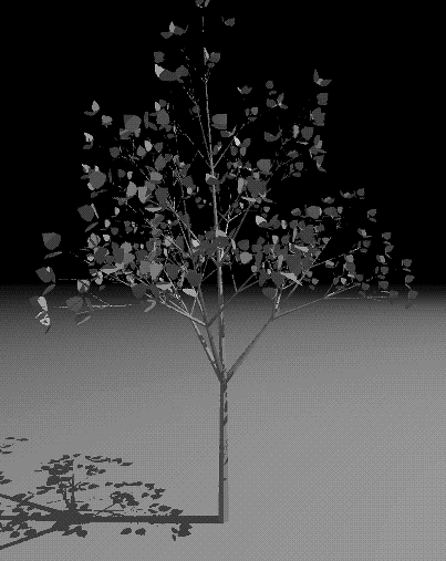
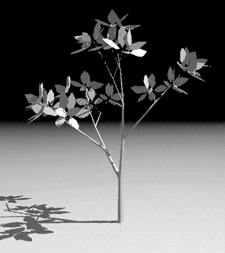
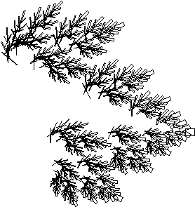
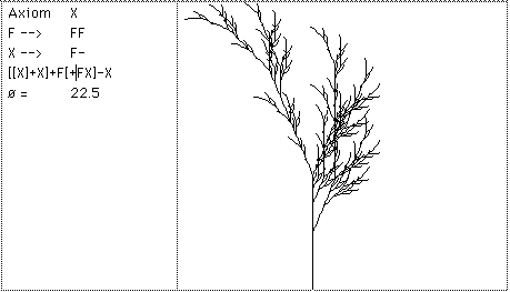
Recent usage of L-Systems is for the creation of realistic looking objects that occur in nature and in particular the branching structure of plants. One of the important characteristics of L systems is that only a small amount of information is required to represent very complex objects. So while the bushes in figure 9 contain many thousands of lines they can be described in a database by only a few bytes of data, the actual bushes are only "grown" when required for visual presentation. Using suitably designed L-System algorithms it is possible to design the L-System production rules that will create a particular class of plant. Further examples:
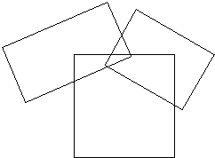
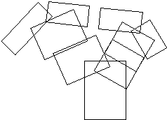
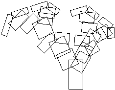
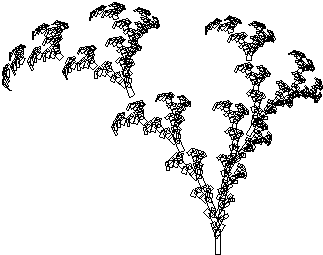
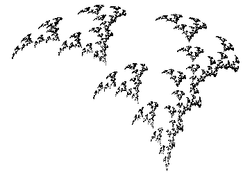
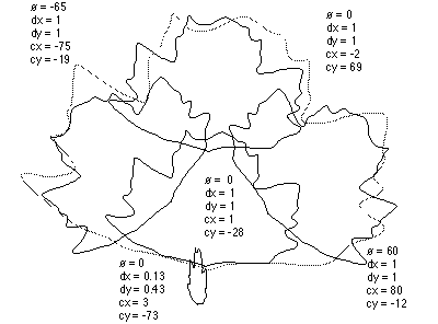
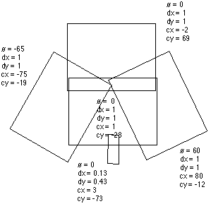
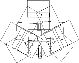
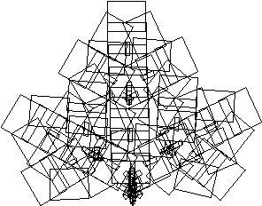
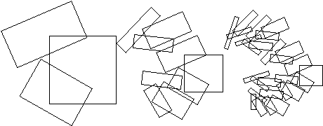
IFS - Iterated Function SystemsInstead of working with lines as in L systems, IFS replaces polygons by other polygons as described by a generator. On every iteration each polygon is replaced by a suitably scaled, rotated, and translated version of the polygons in the generator. Figure 10 shows two such generators made of rectangles and the result after one and six iterations. From this geometric description it is also possible to derive a hopalong description which gives the image that would be created after iterating the geometric model to infinity. The description of this is a set of contractive transformations on a plane of the form 
each with an assigned probability. To run the system an initial point is chosen and on each iteration one of the transformation is chosen randomly according to the assigned probabilities, the resulting points (xn,yn) are drawn on the page. As in the case of L systems, if the IFS code for a desired image can be determined (by something called the Collage theorem) then large data compression ratios can be achieved. Instead of storing the geometry of the very complex object just the IFS generator needs to be stored and the image can be generated when required. The fundamental iterative process involves replacing rectangles with a series of rectangles called the generator. The rectangles are replaced by a suitably scaled, translated, and rotated version of the generator.
Hopalong or "The Chaos Game"
Note that with both methods it is possible to create the image at any scale. In many but not all cases zoomed in examples will be exhibit self similarity at all scales. Applications generally involve data reduction for model files. If a generator can be found for a complex image then storing the generator and the rules of production results in a great deal of data reduction. For example the weed in the examples above might eventually contain over 2000 rectangles but is completely specified by the characteristics of 3 rectangles, only 5 numbers, center (cx,cy), scale (sx,sy), and angle (ø) Note: it is not necessarily trivial to derive a rectangular generator for an arbitrary form, although it is possible to create a polygonal generator for any form. Further examples
IFS Fern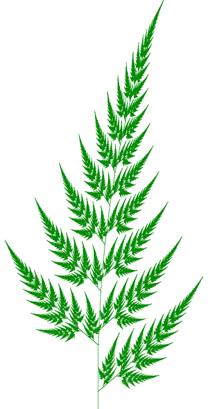
Random IFSWada basins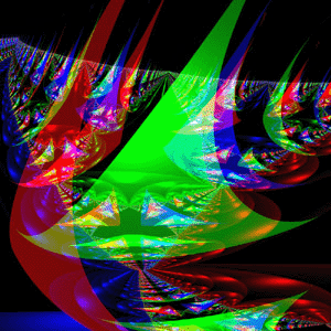
ReferencesBarnsley, M., Fractals Everywhere, Academic press, 1988Barnsley, F., and Sloan, A.D., A Better Way to Compress Images, Byte Magazine, January 1988, Pages 215-222 Blumenthol, Leonard. & Menger, Karl, Studies in Geometry, W.H.Freeman & Co, 1970 Cantor, G., Grundlagen Einer Allgemeinen Mannichfaltigkeitslehre, Mathematische Annalen, 21, p545-591, 1882 Demko, S., Hodges, L., and Naylor B, Construction of Fractal Objects with Iterated Function Systems, Computer Graphics 19, 3, July 1985, Pages 271-278 F.Kenton Musgrave, Craig E Kolb, Robert S. Mace, The Synthesis and Rendering or Eroded Fractal Terrains, IEEE Computer Graphics & Applications Mandelbrot, Benoit., The Fractal Geometry of Nature, W.H.Freeman & Co, NY, 1982 Oppenheimer, P.E., Real Time Design and Animation of Fractal Plants and Trees, Computer Graphics, 20, 4, 1986 Heinz-Otto and Dietmar Saupe, The Science of Fractal Images, Springer-Verlag Barry Martin, Computer Recreations, Scientific American, Sept 1986 Peitgen H, Saupe D, The Science of Fractal Images, Springer-Verlag, NY, 1988 Prusinkiewicz, P, Graphical Applications of L-Systems, Proc. of Graphics Interface 1986 - Vision Interface, 1986, Pages 247-253. Przemyslaw Prusinkiewicz, James Hanan, Lecture Notes in Biomathematics #79 Przemyslaw Prusinkiewicz, Application of L-Systems to Computer Imagery, Lecture Notes in Computer Science #291, Pages 534-548 Prusinkiewicz, P and Lindenmayer A., The Algorithmic Beauty of Plants, Springer Verleg, 1990, Pages 40-50 Reghbati, H.K., An Overview of Data Compression Techniques, Computer, 14, 4, 1981, Pages 71-76 Smith, A.R., Plants, Fractals, and Formal Languages Computer Graphics, 18, 3, 1984, Pages 1-10 |
