Image slicing for fulldome (and other applications)Written by Paul BourkeJune 2015
Multiple projector systems, in this case for fulldome projection, typically slice up high resolution movie content into smaller segments. These segments contain that portion of the image required plus extra for alignment adjustment and edge blending. There is no one slicing, it depends on the projector arrangement, field of view and the other intrinsic optical attributes. The supplier of the projection system will provide the details of how the images should be sliced, this is generally in the form of a 4 sided polygon defined by the 4 corner vertices. The transformation, as illustrated below, requires a warping (image transformation) between the 4 sided polygon to the rectangular image that will be sent to the projector. 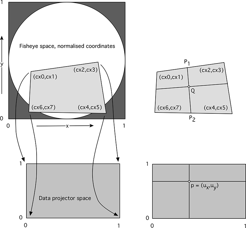
The mathematics for this mapping is straightforward and is outlined below, the symbols refer to the figure on the right in the above illustration. As with all such mapping one needs to find the input pixel for every output pixel, that is, a reverse mapping rather than a forward mapping. If "p" is a pixel in the output image, it can defined in normalized coordinates as shown. In the input image one finds P1 and P2 based upon the value of ux. Then the point Q is found using the value of uy to interpolate between P1 and P2. One can imagine this is a stretching of the polygon space in the input image to the rectangular output image. p1x = cx0 + ux (cx2 - cx0)p1y = cx1 + ux (cx3 - cx1)
p2x = cx6 + ux (cx4 - cx6)
qx = p1x + uy (p2x - p1x)
In practice one needs to perform antialiasing, generally supersampling is the easiest. This means one samples multiple times around the output pixel to be estimated, each time finding the corresponding pixel value in the input image, averaging those values to determine the final output image pixel value. This reinforces the need to work in continuous normalized coordinates rather than integer pixel coordinates. The implementation here as a proof of concept is a C/C++ utility initially intended for UNIX systems, for example flavours of Linux and Mac OSX. The "mapfile" just lists the values of cx0, cx1, cx2, cx3, cx4, cx5, cx6, cx7. The input image is read only once and all the output slices generated from that based upon the map files. slicer [options] imagefilename numberofmapfiles Map files are assumed to be called 0.map, 1.map .... Options: -a n set antialias level, 1 upwards, 2 or 3 typical (Default: 2) -w n n width and height of the output image (Default: 100x100) -m s output file mask, directory and frame number (Default: %d/%05d.tga) -f n output frame number (Default: 0) -d debug mode (Default: false) -h this textNotes
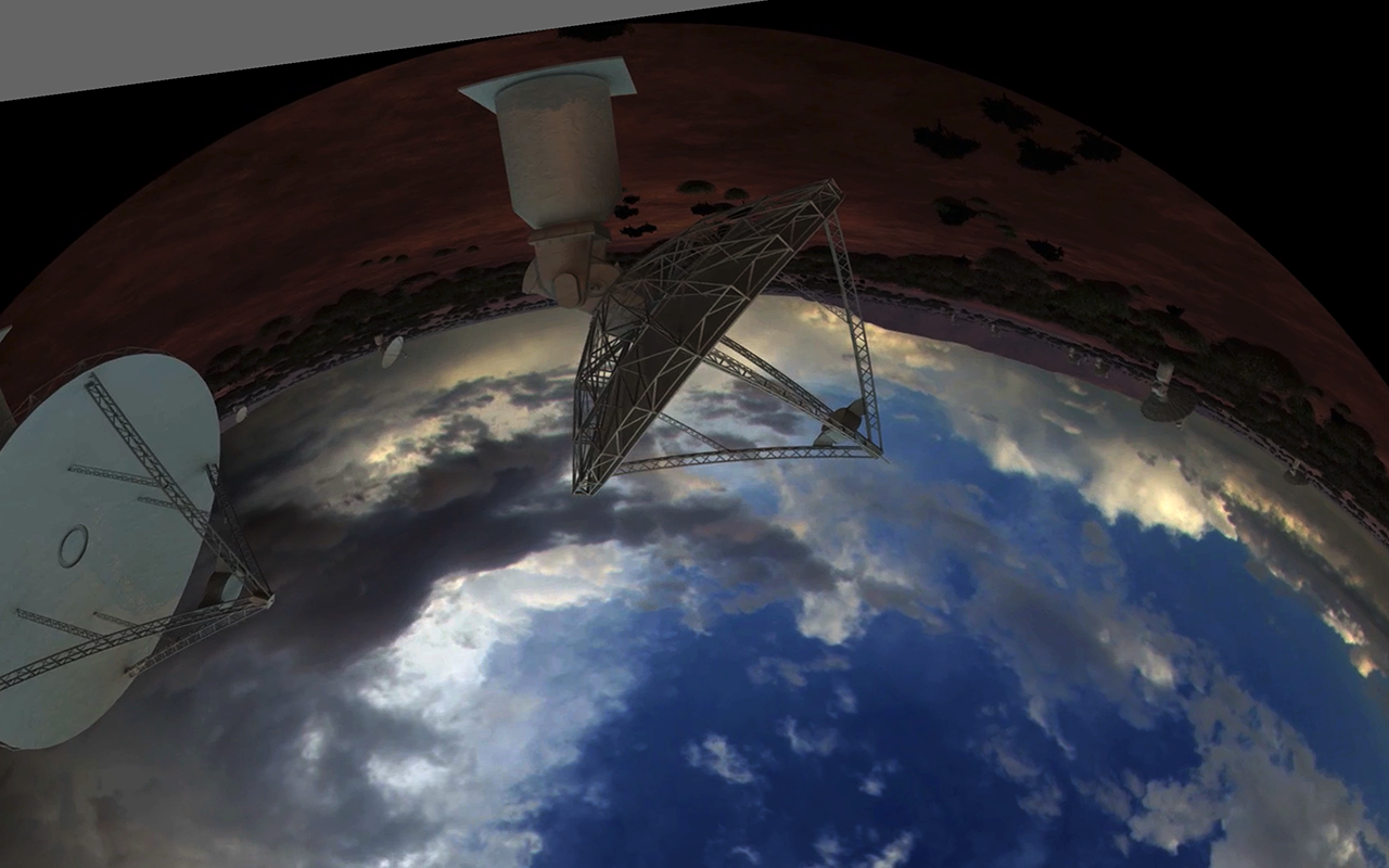
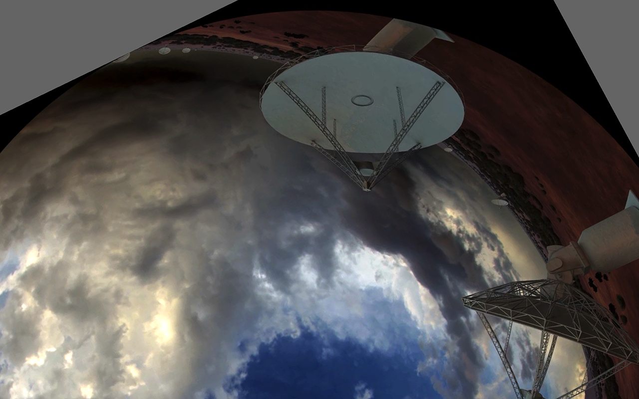
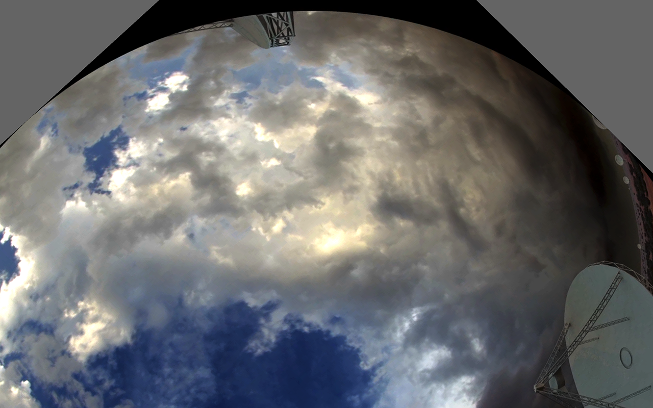
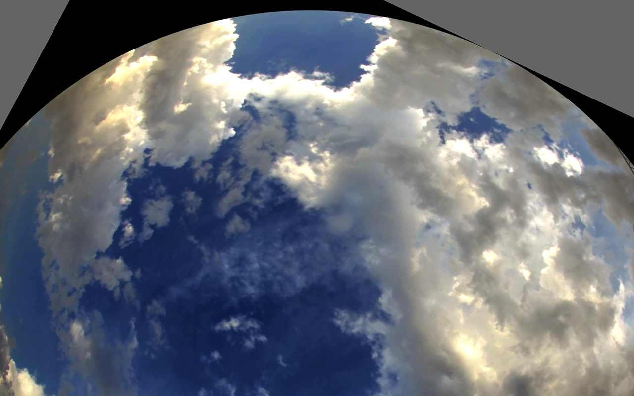
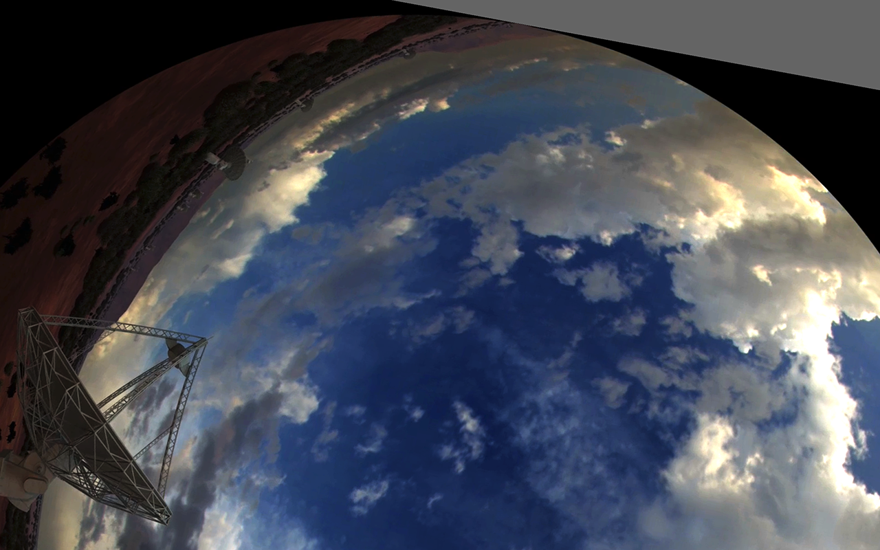
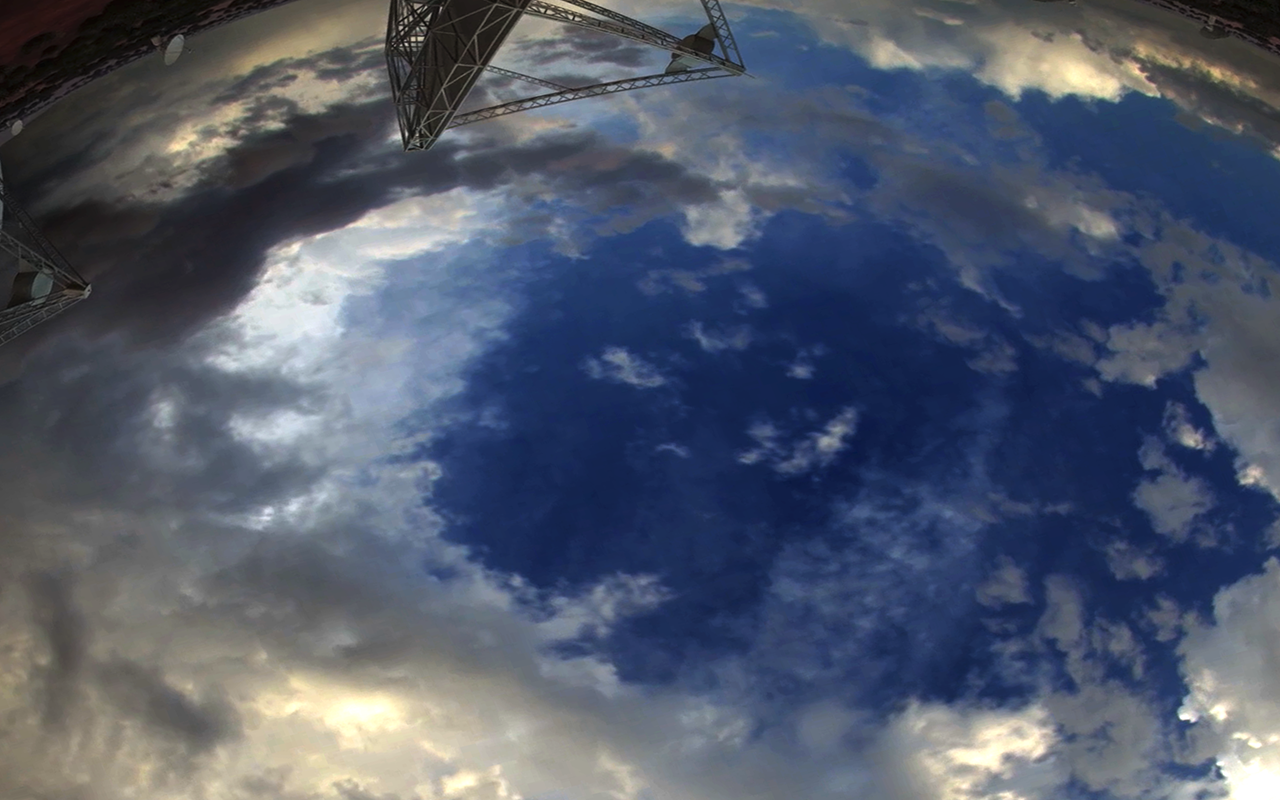
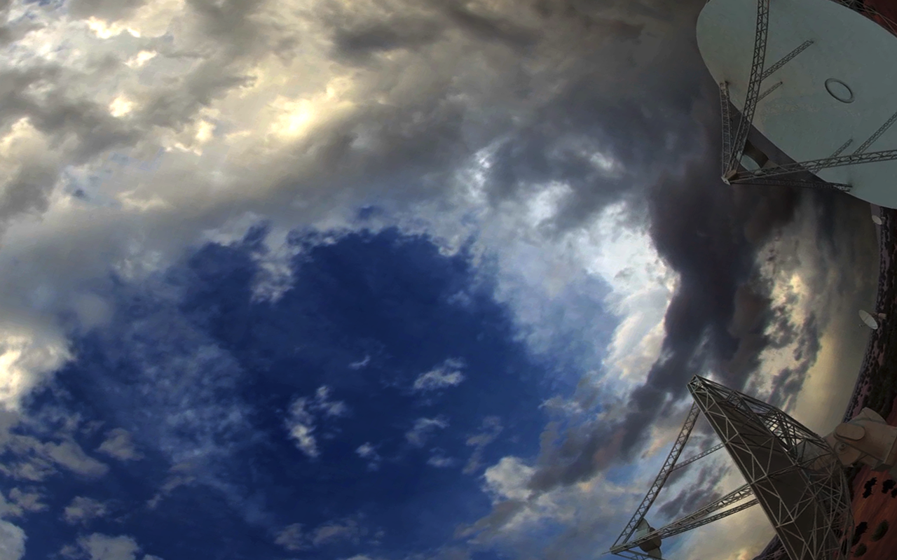
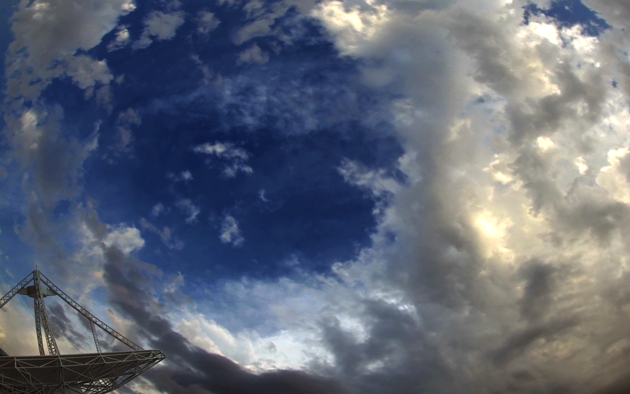
The following polygons are intended for an eight channel fulldome projection system. 0.8070 1.0617 0.0179 0.9514 0.0908 0.4301 0.8799 0.5404 1.1355 0.3859 0.7723 1.0956 0.3033 0.8555 0.6665 0.1458 0.5817 -0.1349 1.1553 0.4180 0.7901 0.7969 0.2165 0.2440 -0.0791 0.2156 0.6336 -0.1415 0.8713 0.3330 0.1586 0.6901 0.0661 0.9604 -0.0840 0.1879 0.4243 0.0892 0.5744 0.8617 0.6872 0.8771 0.0728 0.6824 0.2336 0.1751 0.8480 0.3698 0.6927 0.1318 0.9060 0.7380 0.4055 0.9142 0.1922 0.3080 0.0770 0.4648 0.5648 0.0431 0.9146 0.4478 0.4268 0.8695 The following is one frame from the Dark fulldome movie. Note the original is a 4K fulldome production. 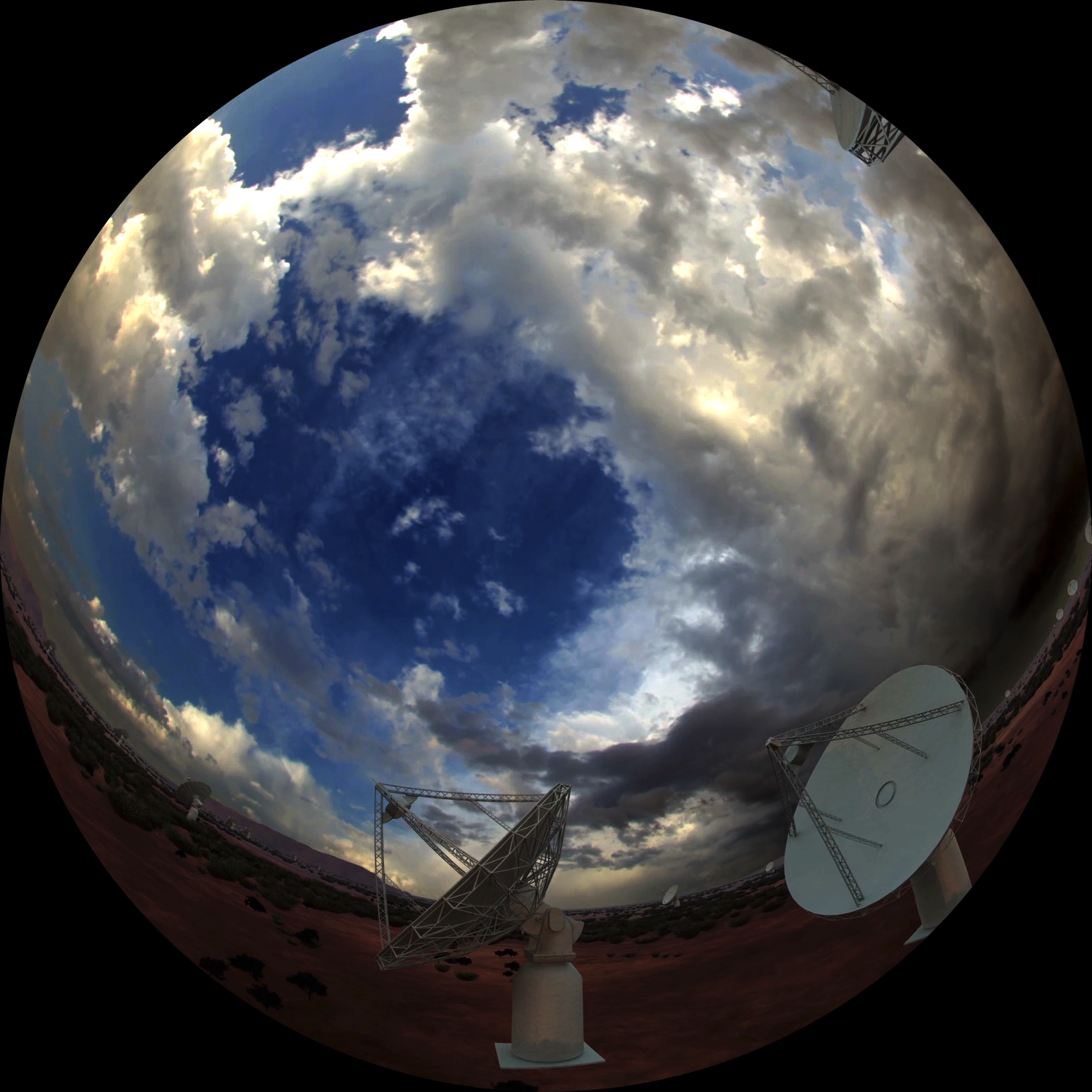
The eight resulting output images are below. The grey regions are those where the polygon extended outside the image bounds, normally this would be shaded black but left grey here of illustrative purposes.
The example presented here is performed solely on the CPU and as implemented is only single core. As it happens the process of applying this is real life to movie sequences is highly parallel, simply by splitting the frames up into sections or applying N conversions to frames modulo N. An alternative would be to perform this on the GPU. Another is to use OpenGL (or DirectX) and treat each frame as a texture on an appropriate mesh. |