Magic Planet Display: How ToSee also: Magic Planet display presentationWritten by Paul Bourke May 2012, updated April 2022
Update: September 2021 An improved method for calibrating a Magic Planet display is doumented here: Magic Planet Display Calibration.pdf.
Introduction
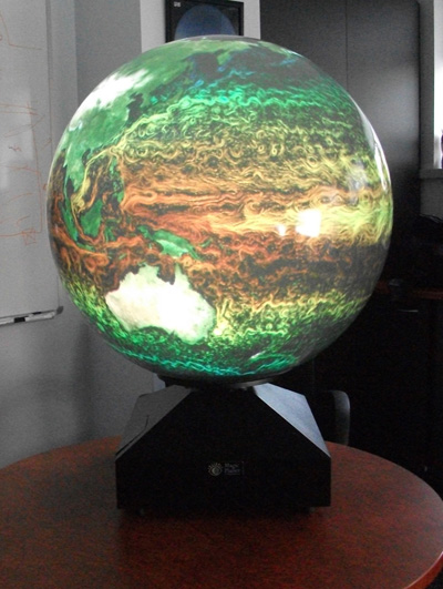
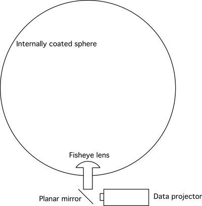
In the following the Magic Planet display will be discussed from generally a technical perspective and how one might create content. The display itself is one of a number of similar systems on the market, indeed there are many home built versions as well. There are a number of ways one might project onto the surface of a sphere, these include multiple interior projectors inside a rear projection globe surface and multiple projectors projecting onto the outside of the sphere. In this case there is a single projector and a fisheye lens in the base of the sphere. Compared to multiple projectors this greatly simplifies the system, reduces the dimensions and cost, and by hiding the projection hardware adds to the overall elegance.
Any content for a display such as this needs to be created in an image format that captures the spherical field of view of the display. While one can make up a range of possible formats, there are three in fairly common usage: cubic maps also known as environment maps, 360 degree fisheye, or spherical projection also known as equirectangular projection. Cubic map projection
This is to imagined as a cube surrounding the camera folded out and presented flat. 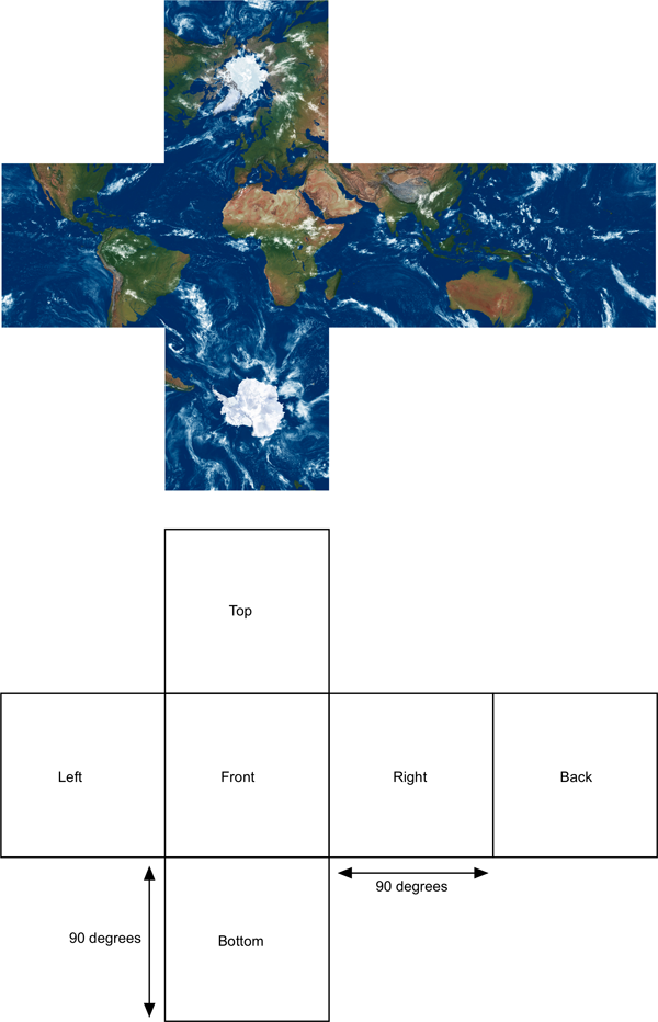
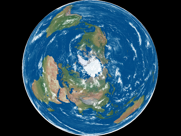
360 degree angular fisheye projection
Note the outer rim of the circle maps to a single point at the south pole. The center of the circle is the north pole. 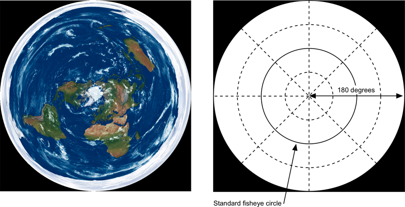
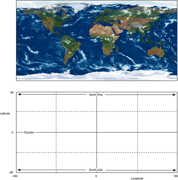
Spherical projection
This is perhaps the more widely known projection. The top edge maps to a single point at the north pole, similarly the bottom edge maps to the south pole.
The data projector takes an image, in this case as a 4x3 aspect rectangle (resolution SXGA: 1400x1050 pixels) and the central circular portion is projected into the sphere. An example of this is illustrated below. To be clear, the pixel in the center of the image is mapped to the north pole of the sphere. A ring about 70% of the radius of the circle is projected onto the equator of the sphere. The outer rim of the circle projects to the lowest rim of the sphere. Circular projected image
The requirement then for the content generation software is to create an image in one of the three projection formats presented above. Then that image is image mapped (warped) into the form of the circular image to be projected. Note that this mapping is highly non-linear. This mapping can be derived in a number of ways, one is to create a simulation of the optics and geometric arrangement of the components. The approach here is the same employed by the software supplied with Magic Planet, namely a curve which describes where a point on the sphere appears on the circular image. Since the lens is assumed to be circularly symmetric in longitude this is only a one dimensional mapping between latitude and radius on the circular projected image plane. There are three standard Magic Planet display sizes and each has its own geometry/optics. Supplied with each display is a default calibration file, this is a straight line approximation to the real lens curve derived by measuring the radial distance on the image for known latitudes. The solid lines in the following figure are the latitude to radius mappings supplied. For this exercise it was decided to fit a simple curve through these points to create a smooth continuous parametric mapping. 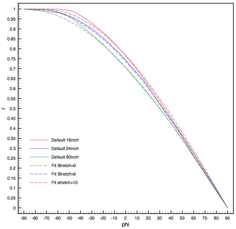
To a first approximation the analytic curves (solid colour for each display size) above can be fitted with a parameter free function, namely 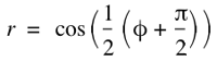
For an idealised geometry this can also ready be derived as the form of the mapping. In summary the above allows one to map a latitude value to a radius on the projected circular image. The angle on the projected image is mapped directly to longitude, the lens is radially symmetric. Details not explicitly discussed here include two further parameters. The first is the realisation that the projected image does not go all the way to -90 degrees, the South pole. This then forms a minimum angle for the circular projected image. The second is that the circular image is not necessarily exactly centered on the lens which manifests itself as a skewing of the image on the sphere, a translational offset is provided for to compensate for this. 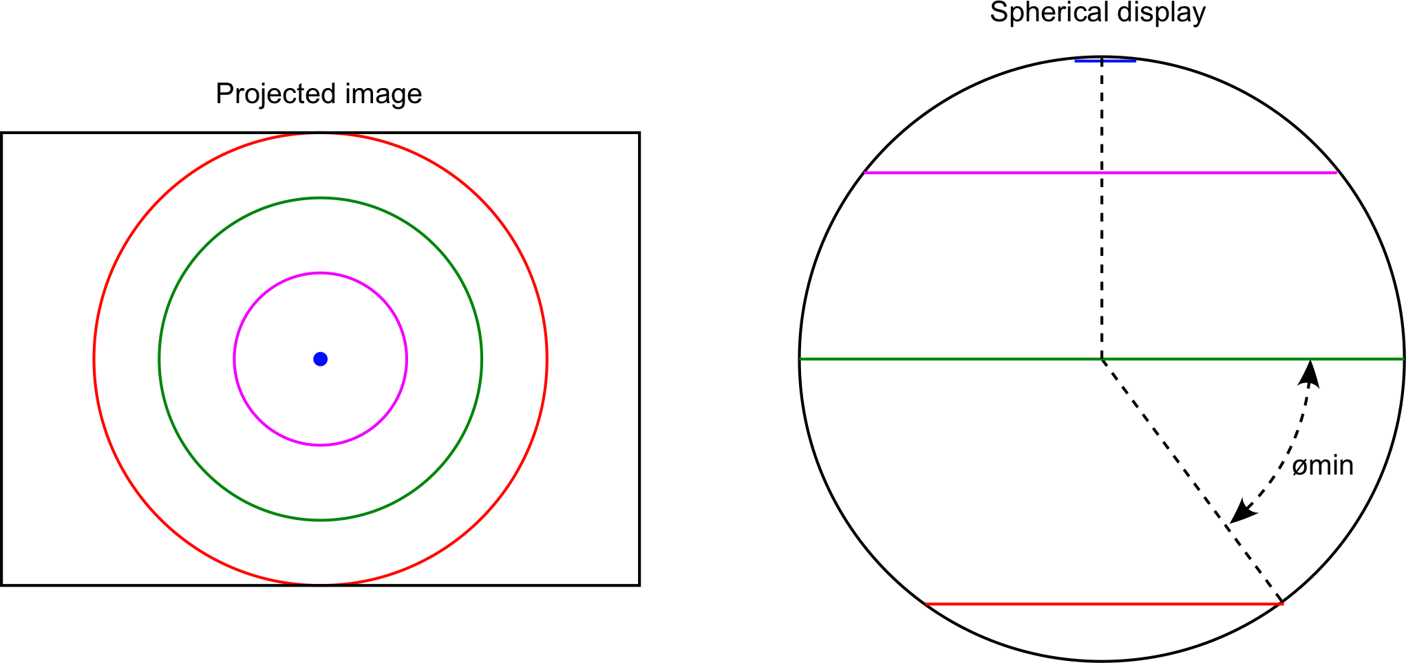
|