iDome galleryWritten by Paul Bourke
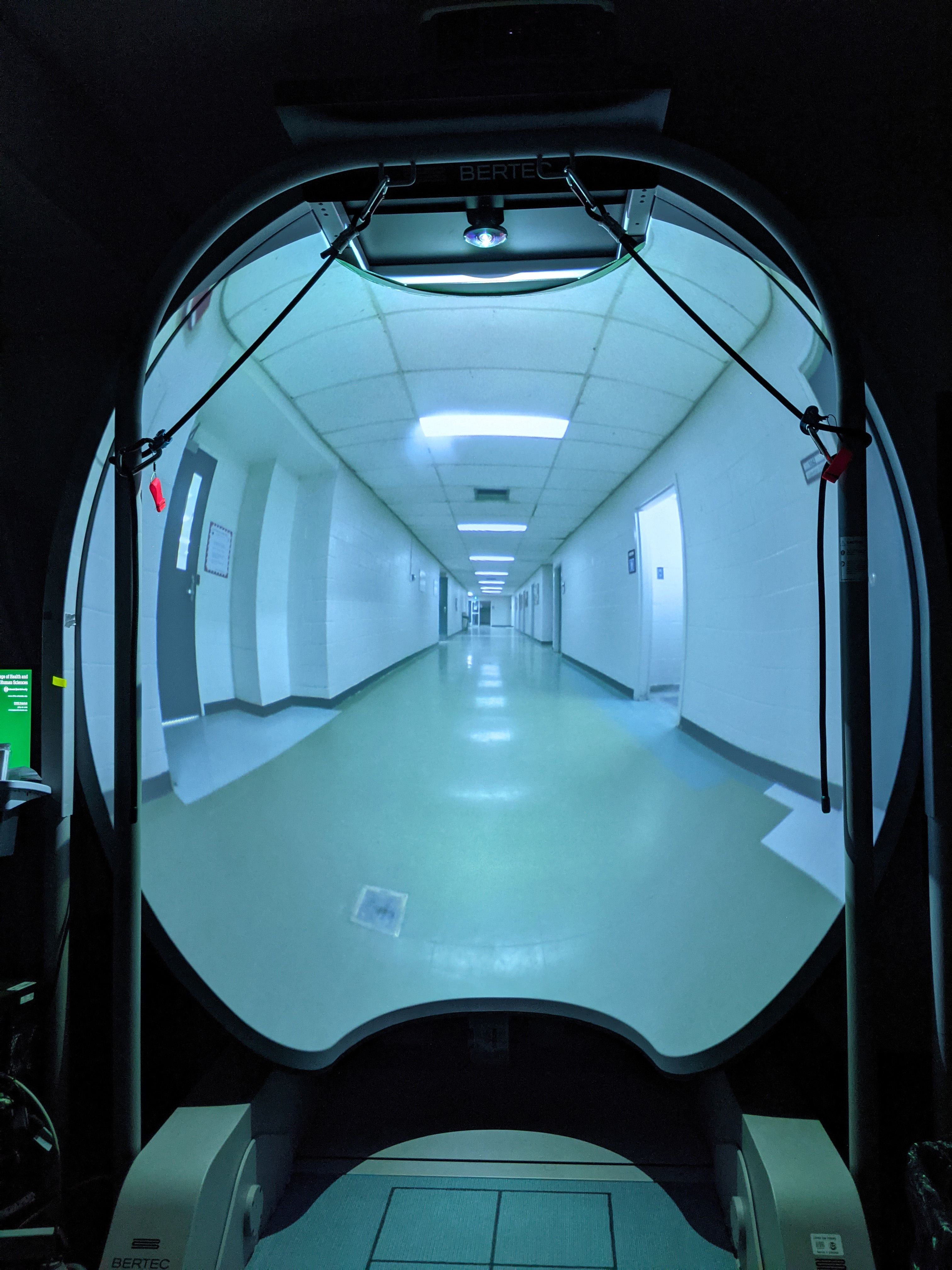
The following provides specifications, example applications, and general photographs and information related to the iDome .... a personal hemispherical dome environment. While the iDome can use a fisheye lens on a data projector, the projection system used below is based upon the spherical mirror, an innovation by the author. For other dome projection solutions see this installation page and this page for offaxis fisheye projection.
Stereoscopic enabled iDome (2025)
Baptist University (2023)
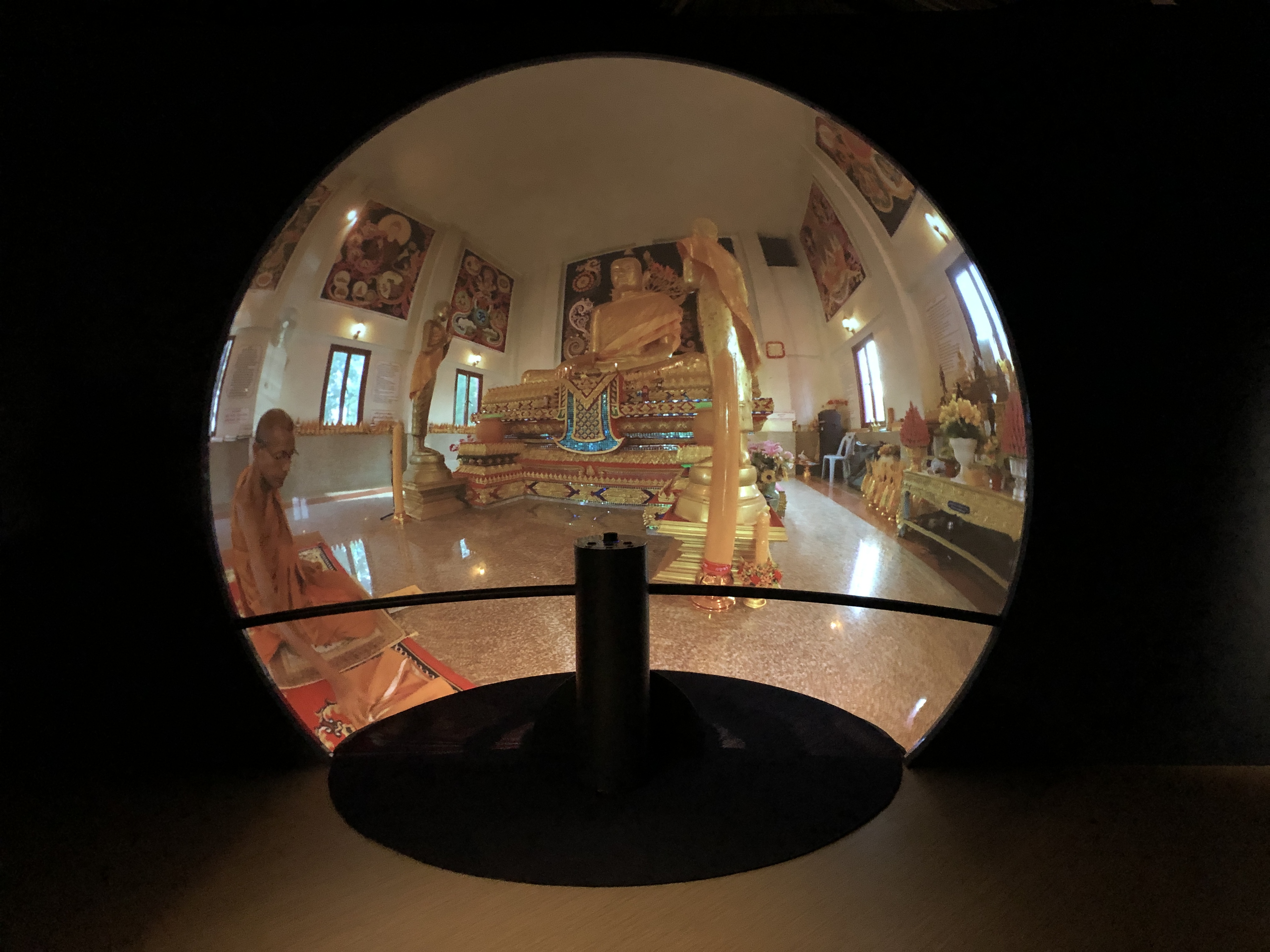
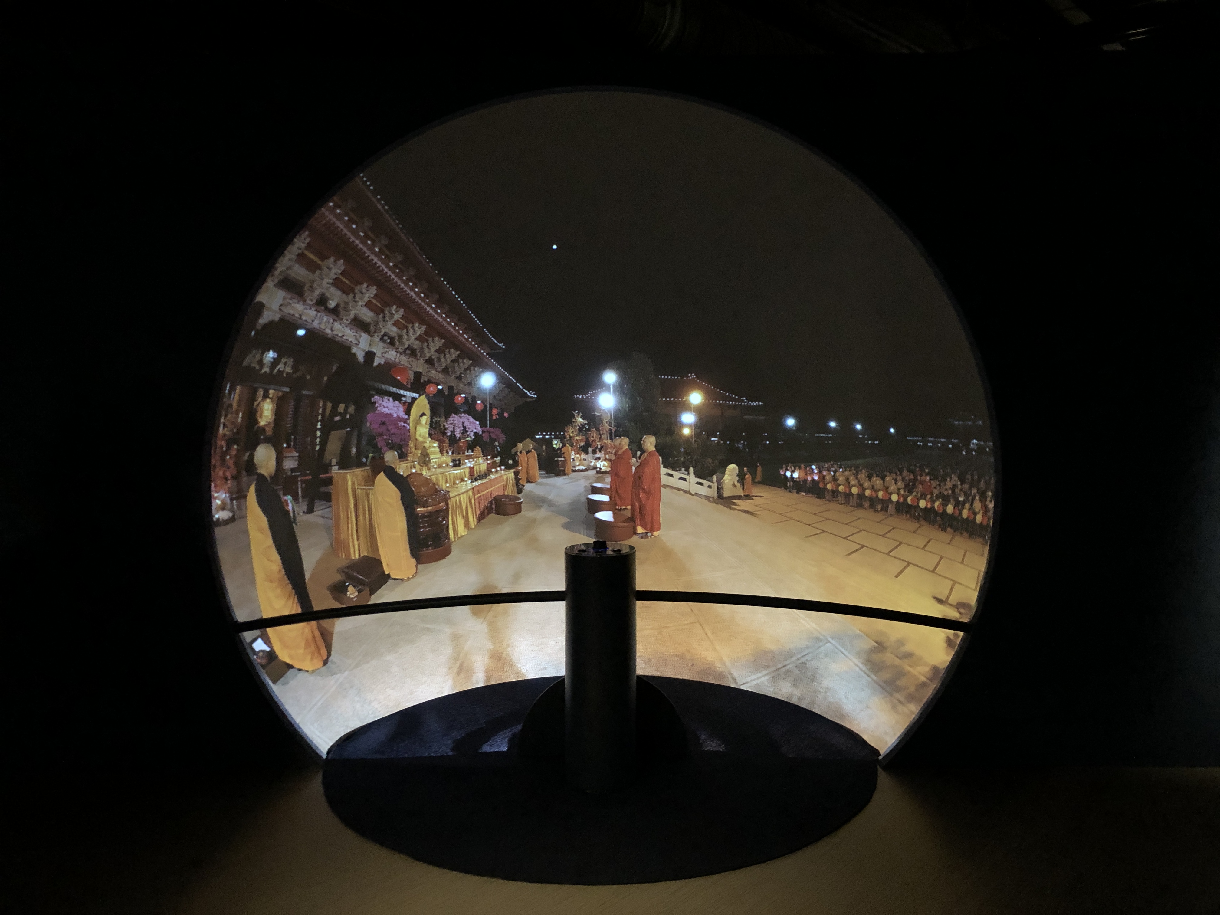
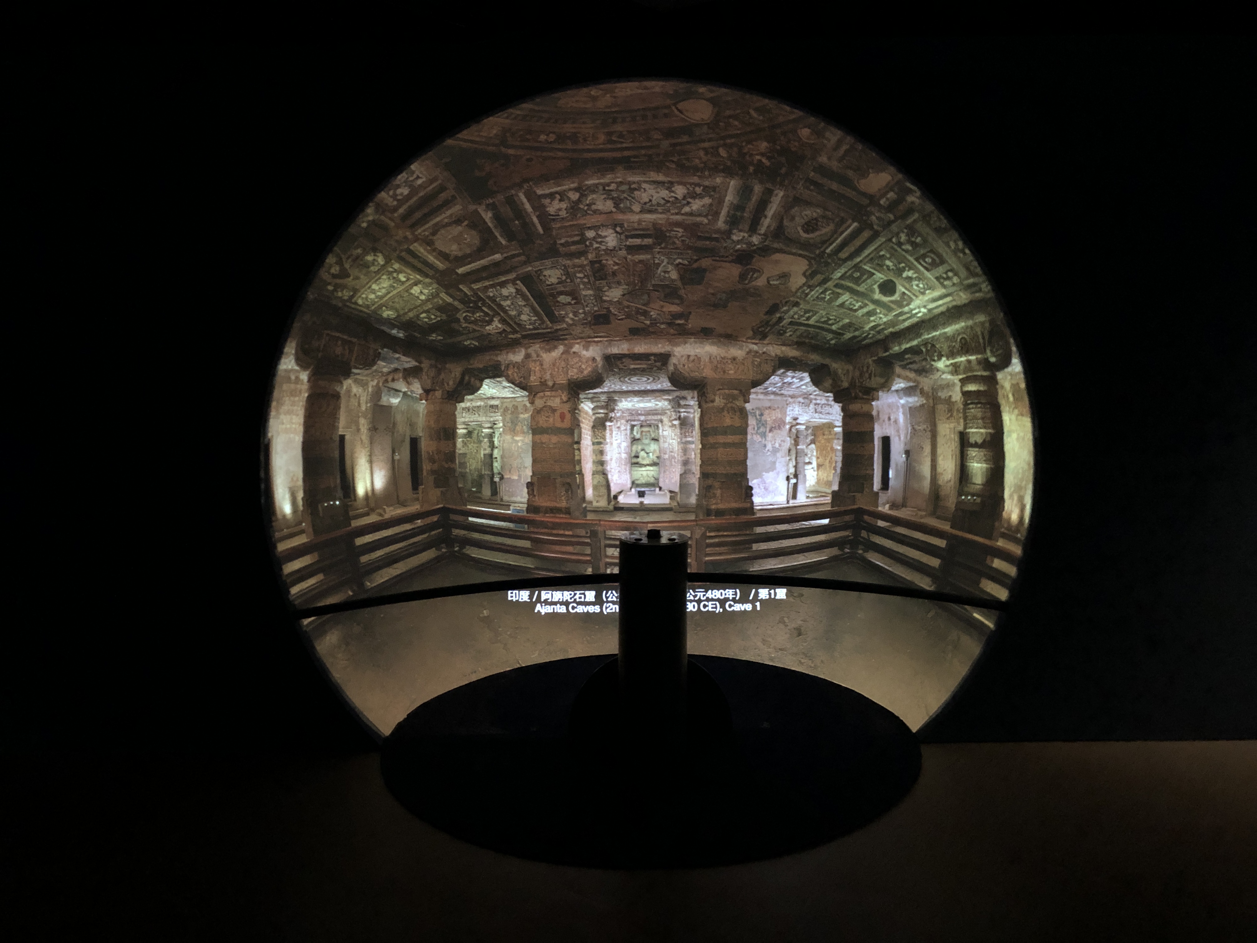
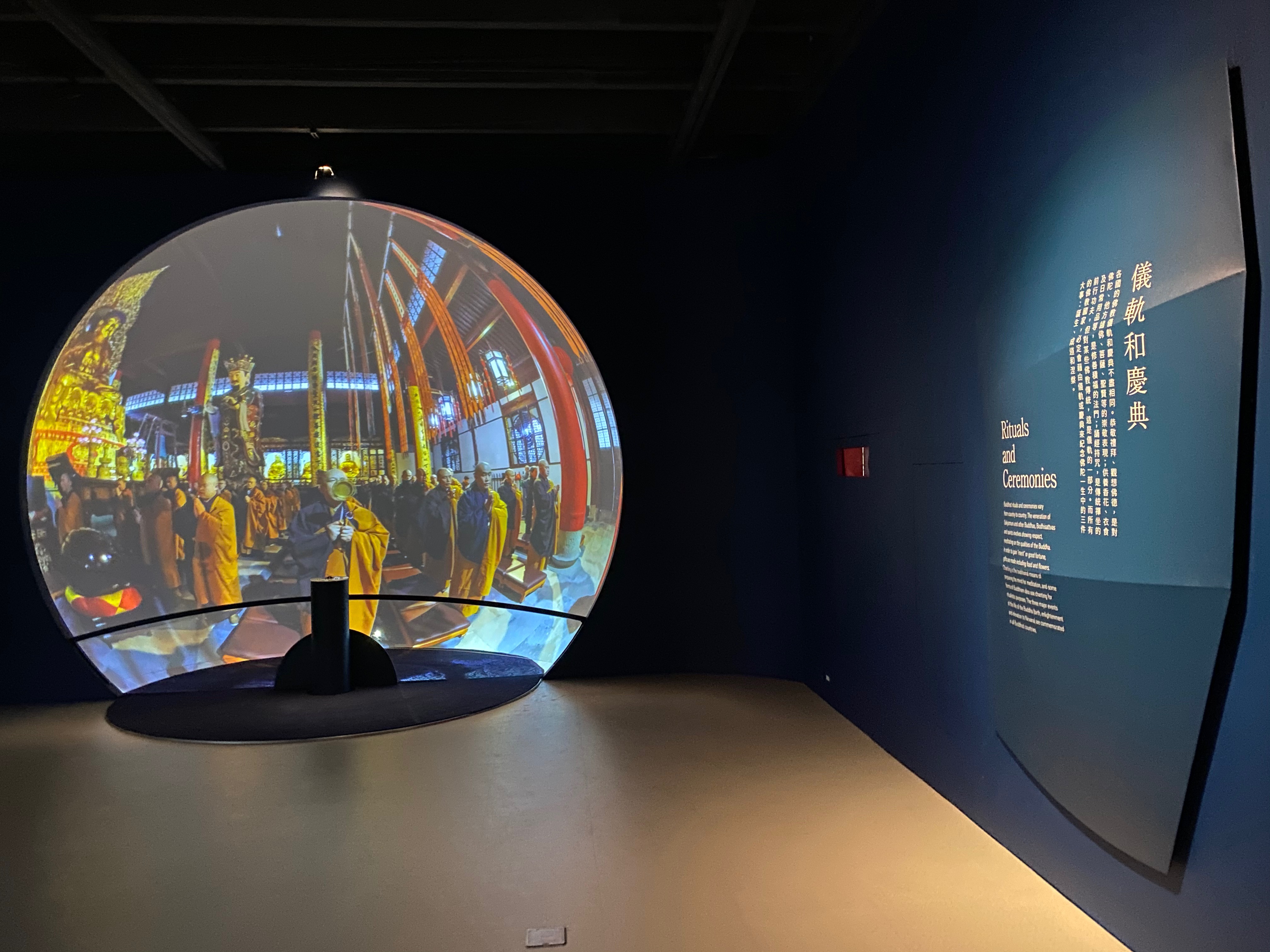
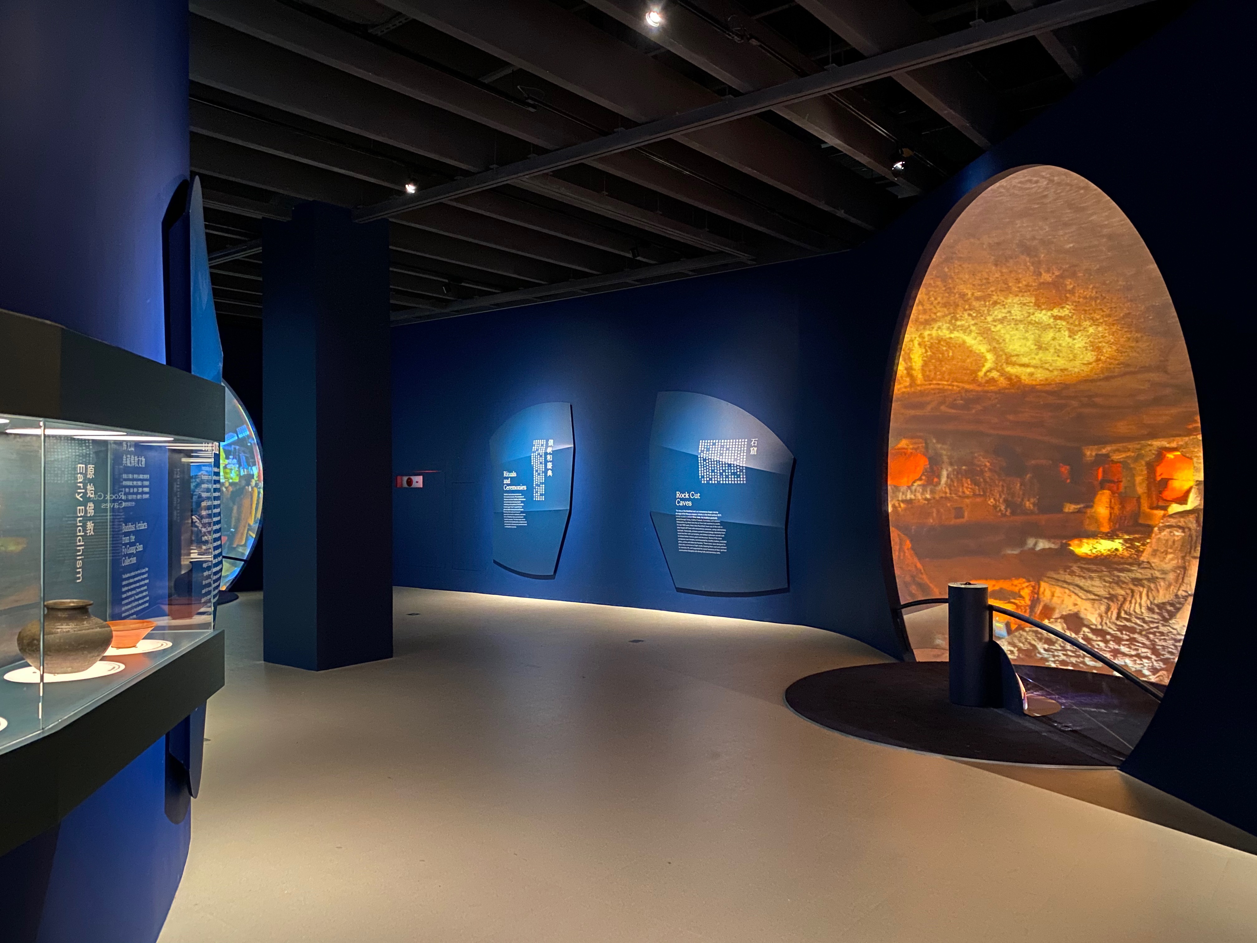
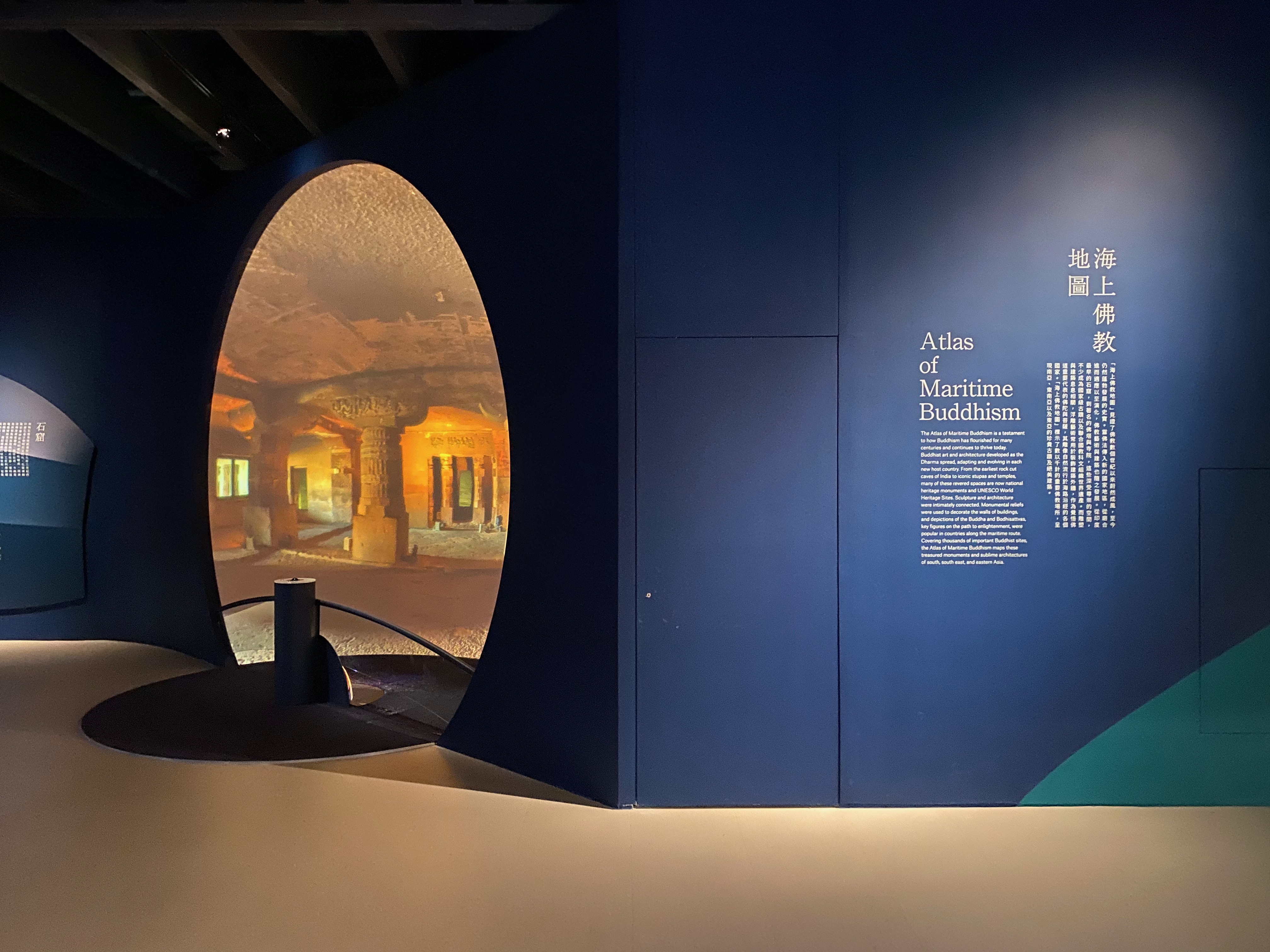
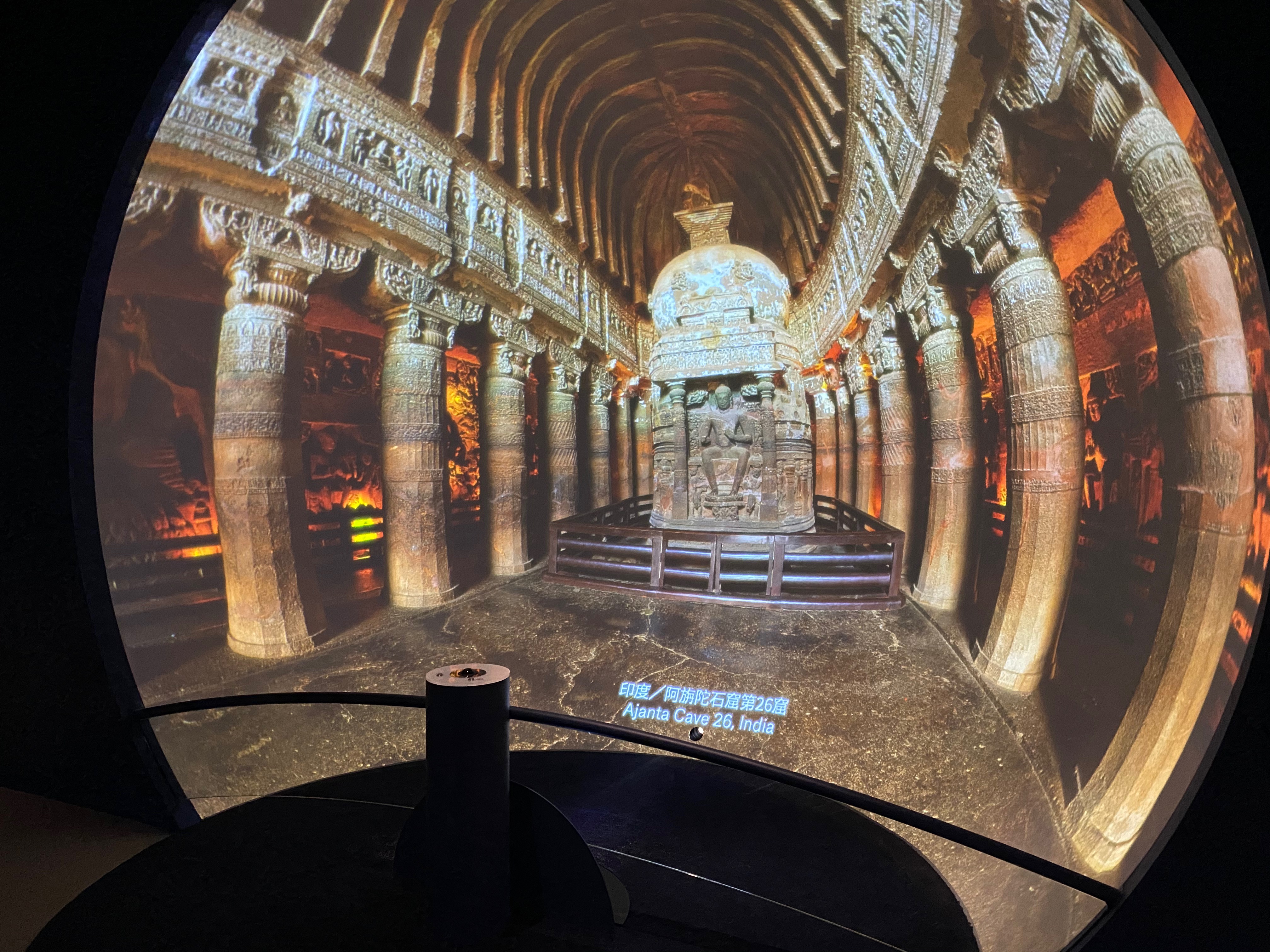
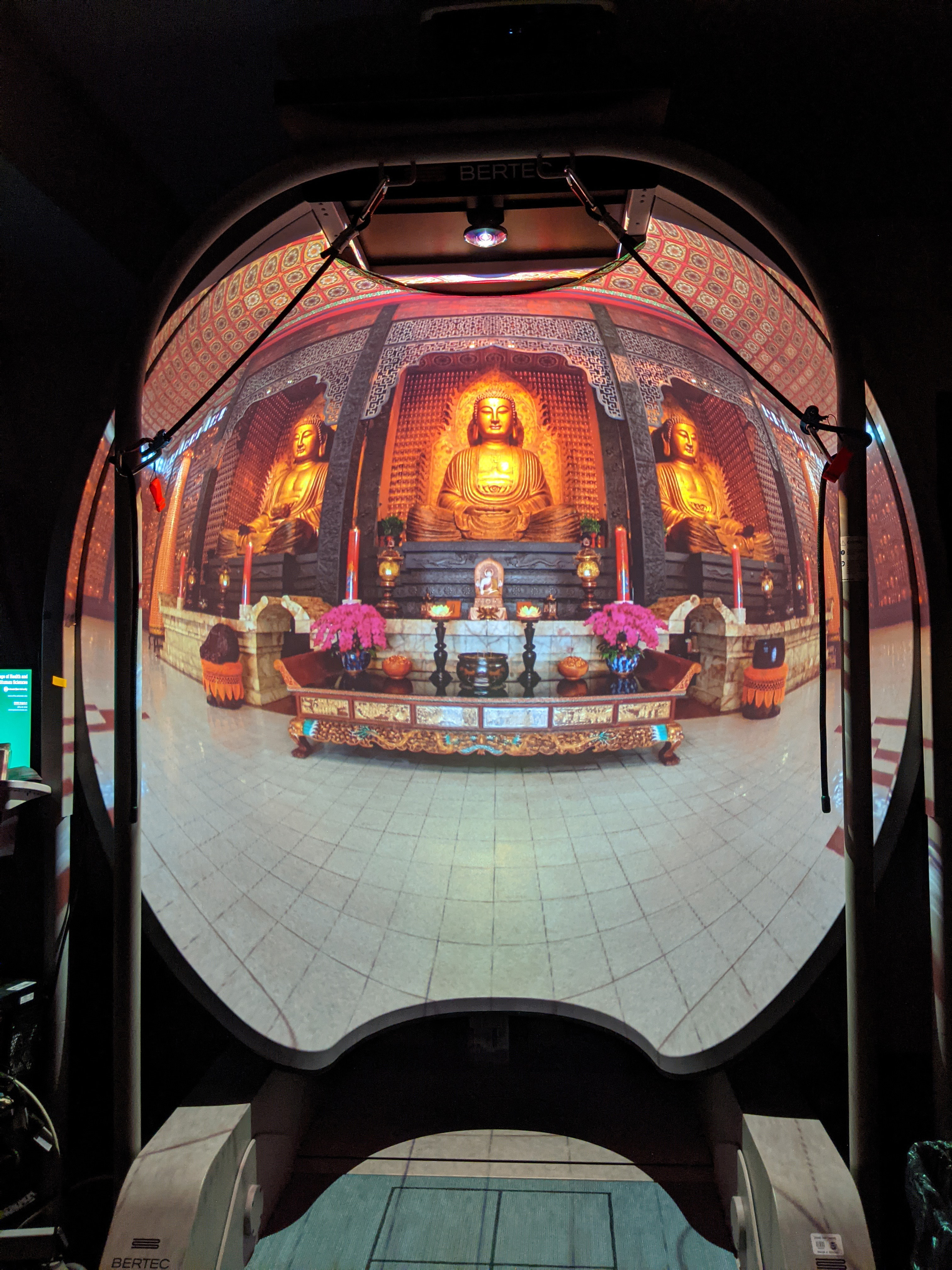
Tsz Shan Monastry (2023)
Curtin University, Perth CBD (2022)
CityU, Hong Kong (2021)
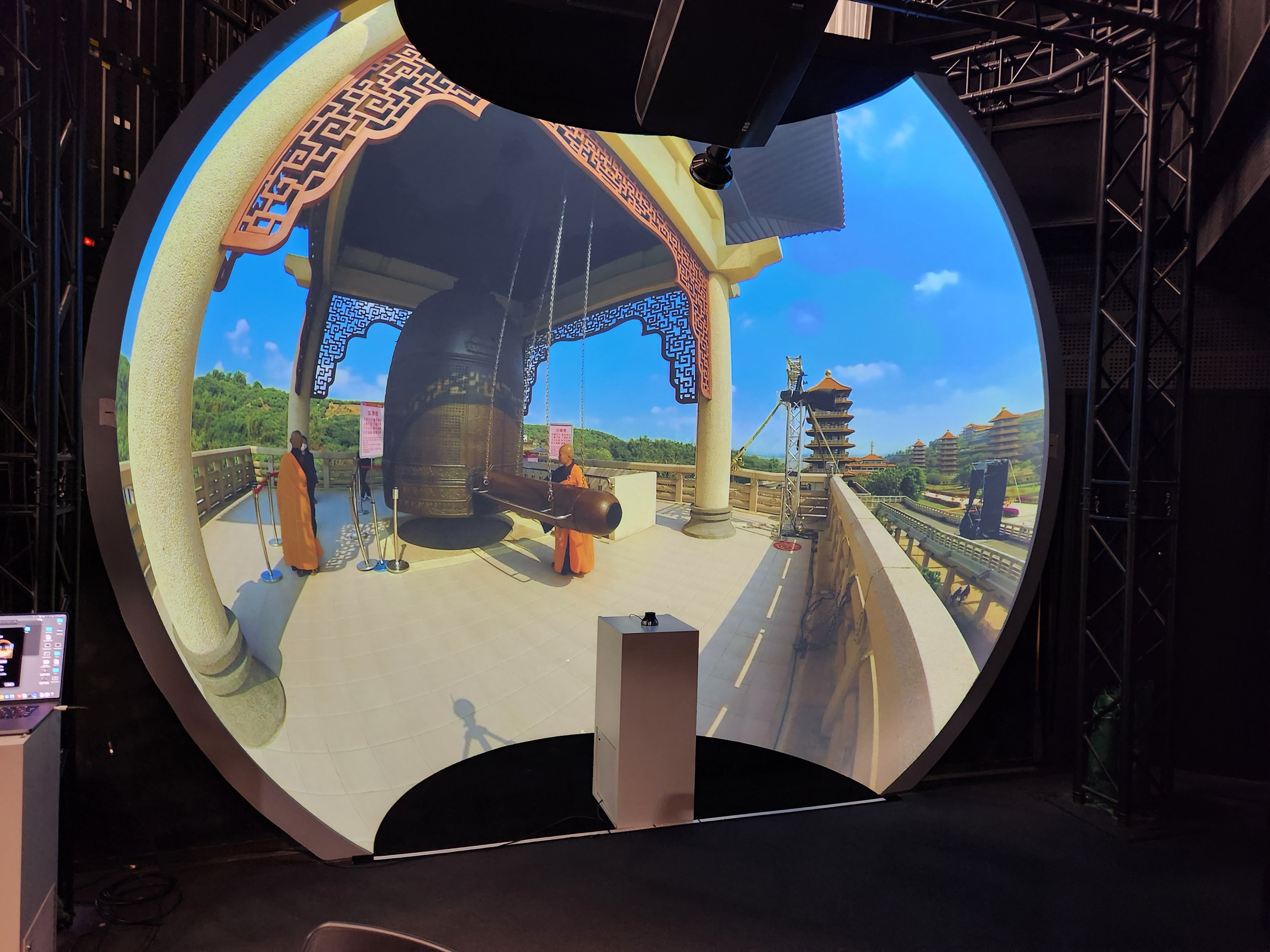
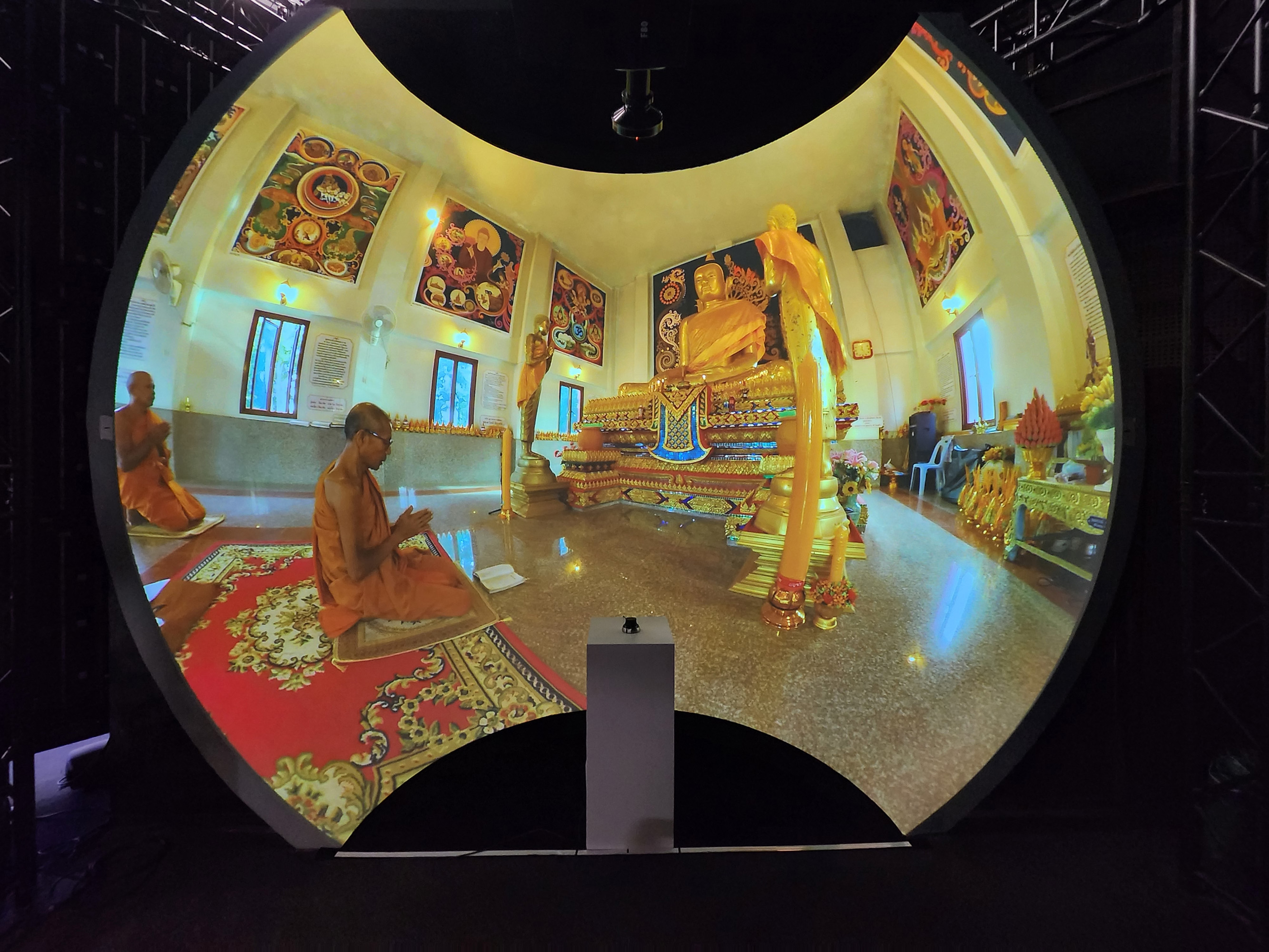
Fo Guang Shan, Kaohsiung, Taiwan (2021)
The HIVE, Curtin University (2020)
The first 4K resolution iDome, October 2019
Older installations, historical information only

Earlier images from a lower resolution projectorWritten by Paul BourkeApril 2006
First orientation for the spherical mirror projection in an upright domeWritten by Paul BourkeMay 2005
Introduction
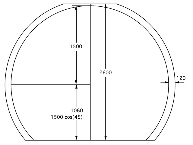
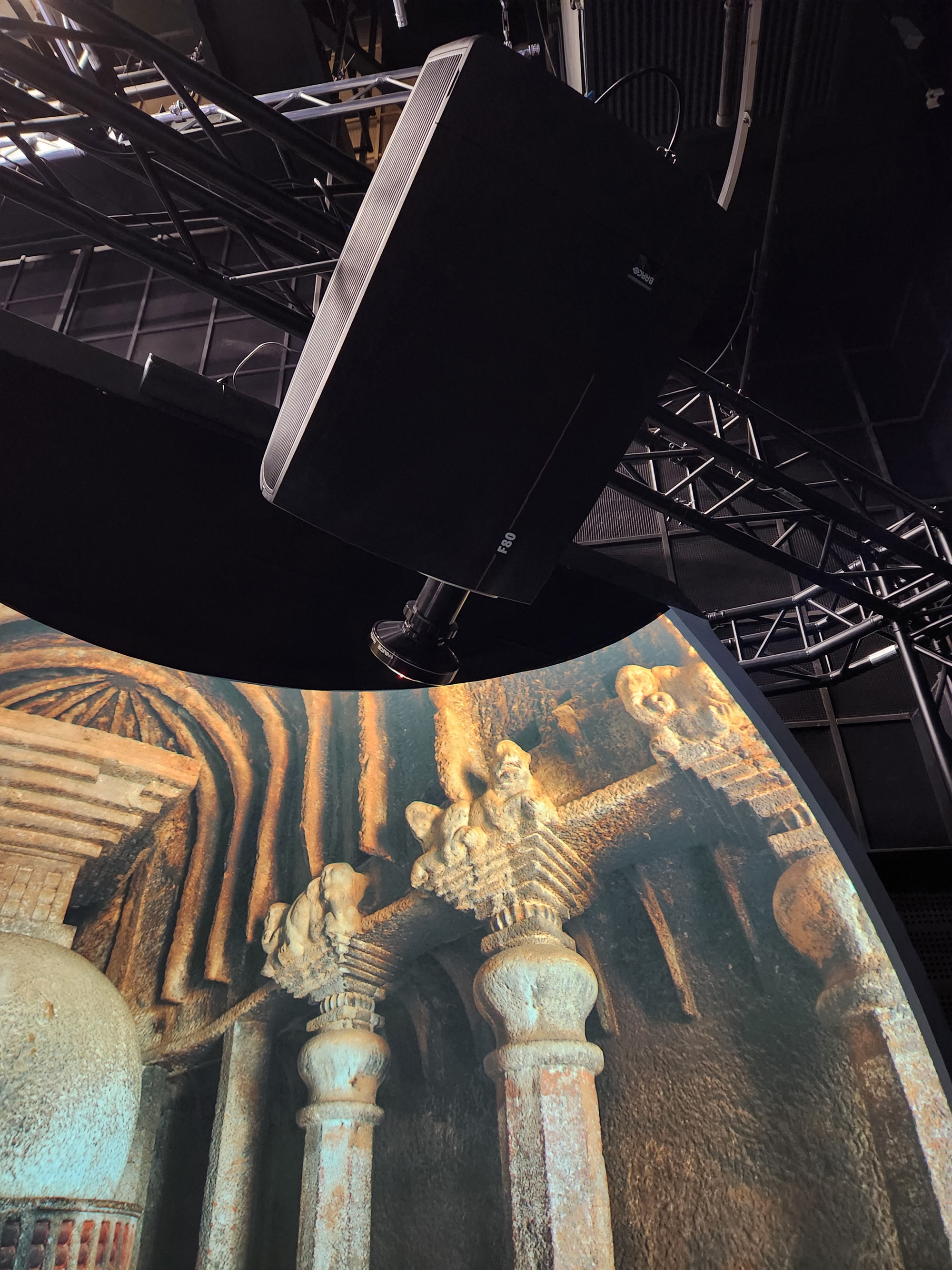
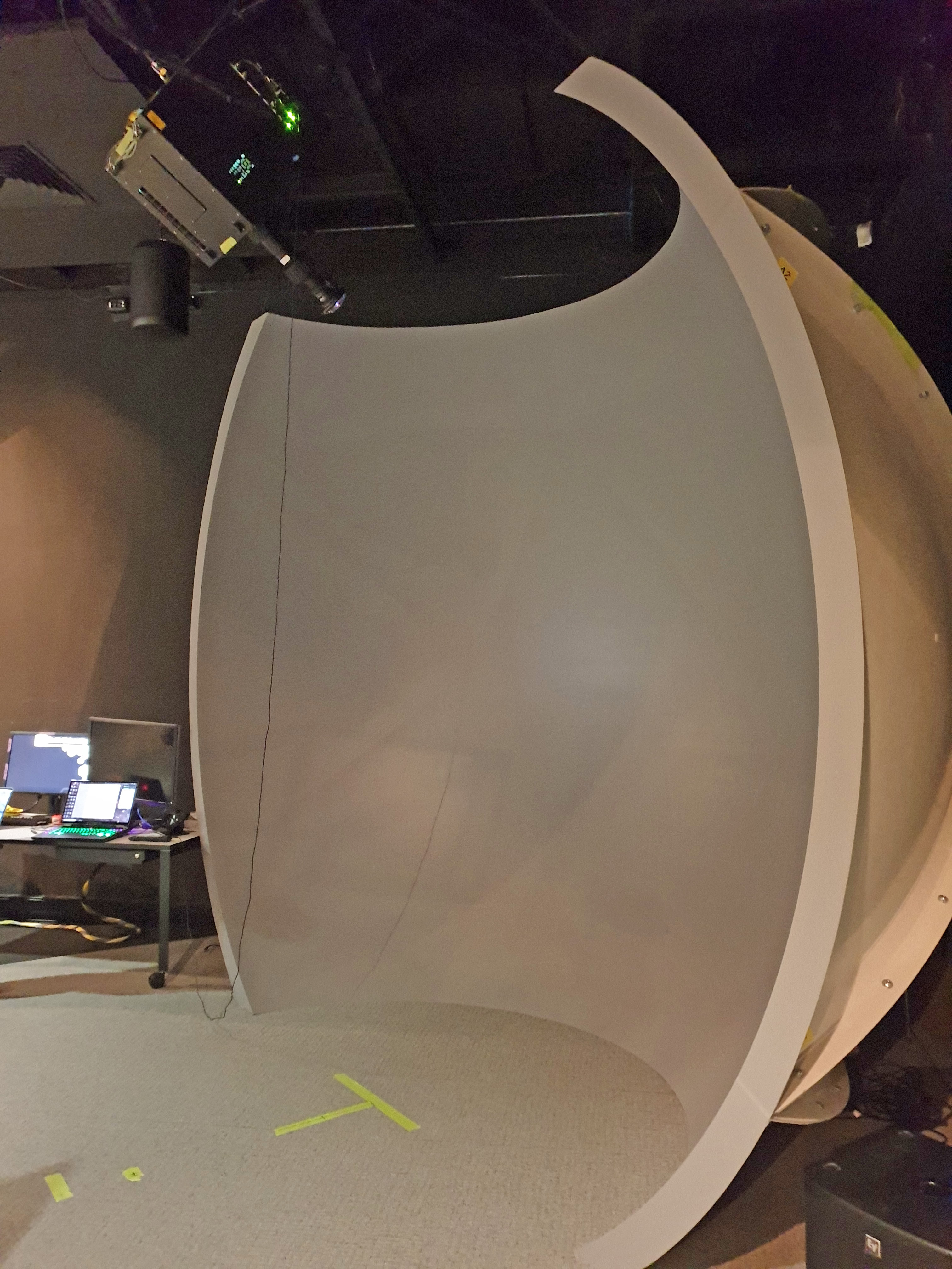
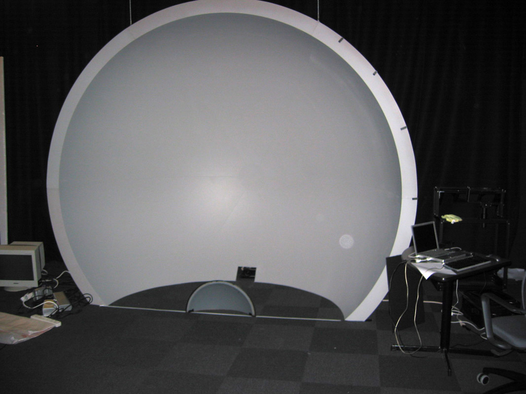
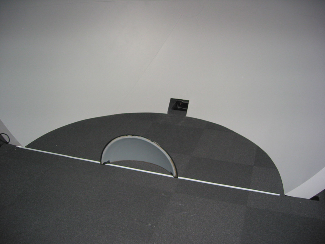
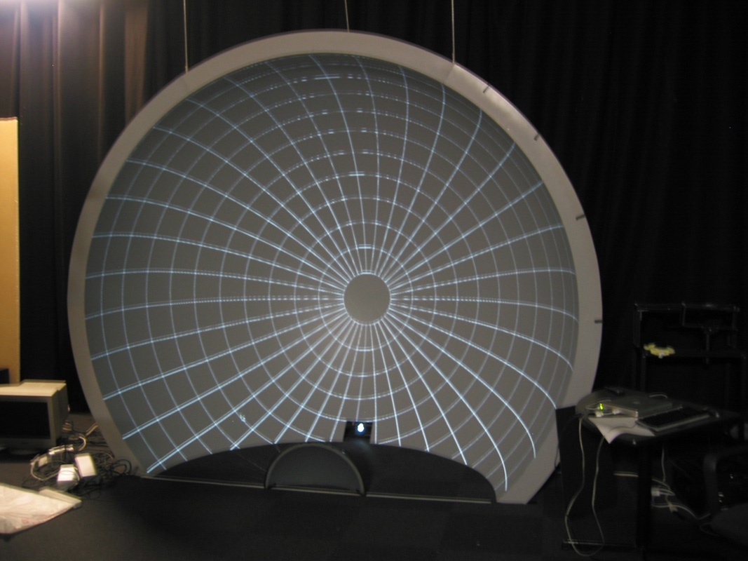
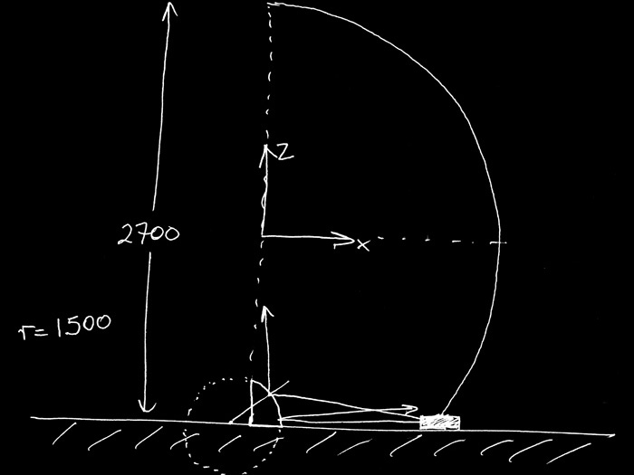
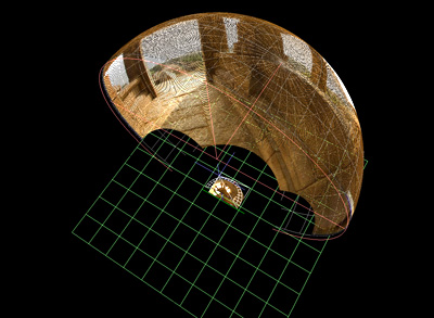
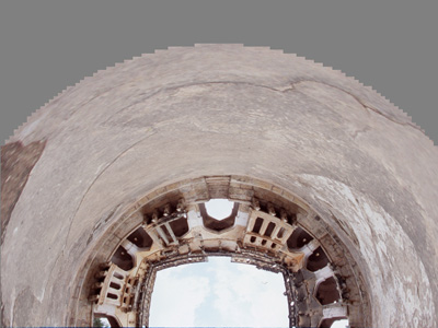
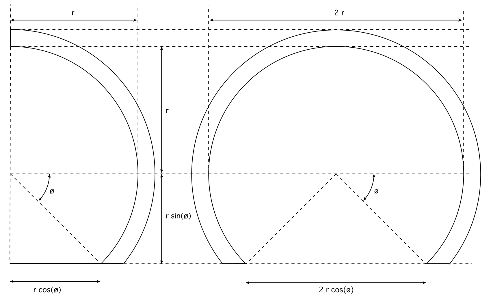
The following illustrates a modified version of my spherical projection for planetarium domes for an upright dome. In this case a truncated dome, a common arrangement when using a fisheye lens and a standard data projector. The projector here points towards the floor where the spherical mirror is positioned. Partial or almost complete dome projection can be achieved. Dome geometry
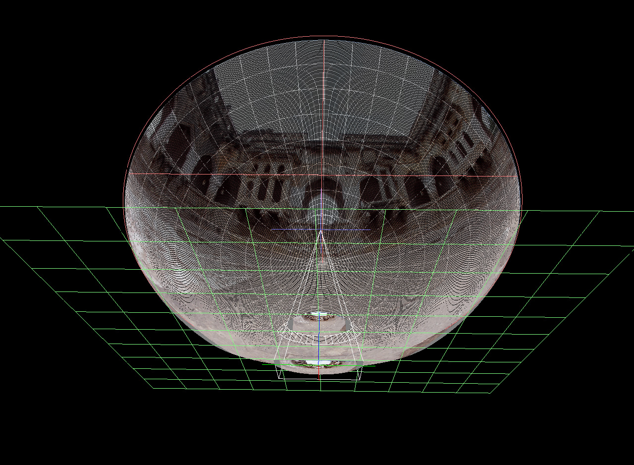
 Simulation (derives warping mesh)
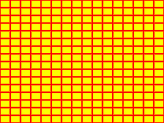
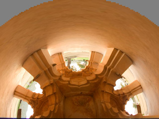
The images to be projected are fisheye and are warped (using textures applied to a mesh in OpenGL). The only trick then is to derive the texture coordinates, this is achieved by writing a simulator that replicates the optical geometry of the physical system. Rays are traced through points on the image plane, they are reflected by the mirror and the intersection on the dome determined. Using this information the (u,v) texture coordinates for the point on the image plane can be calculated.
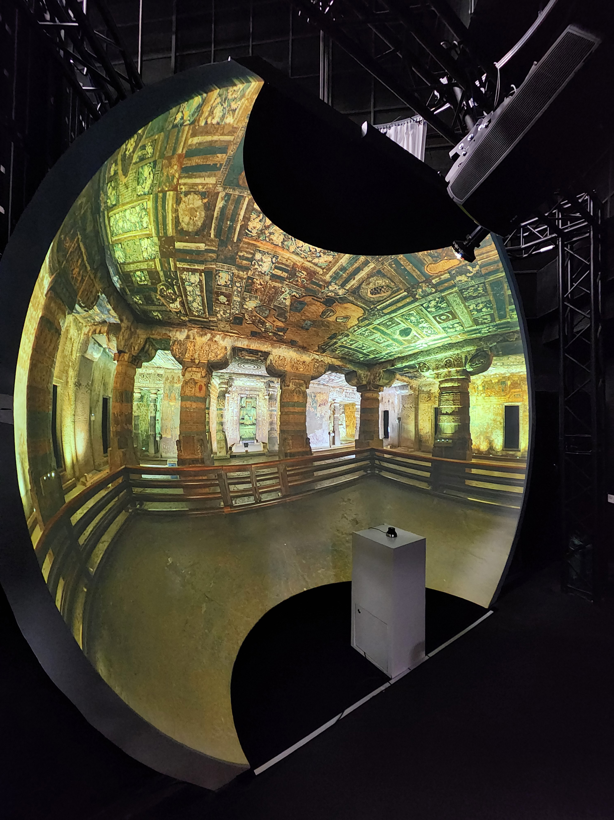
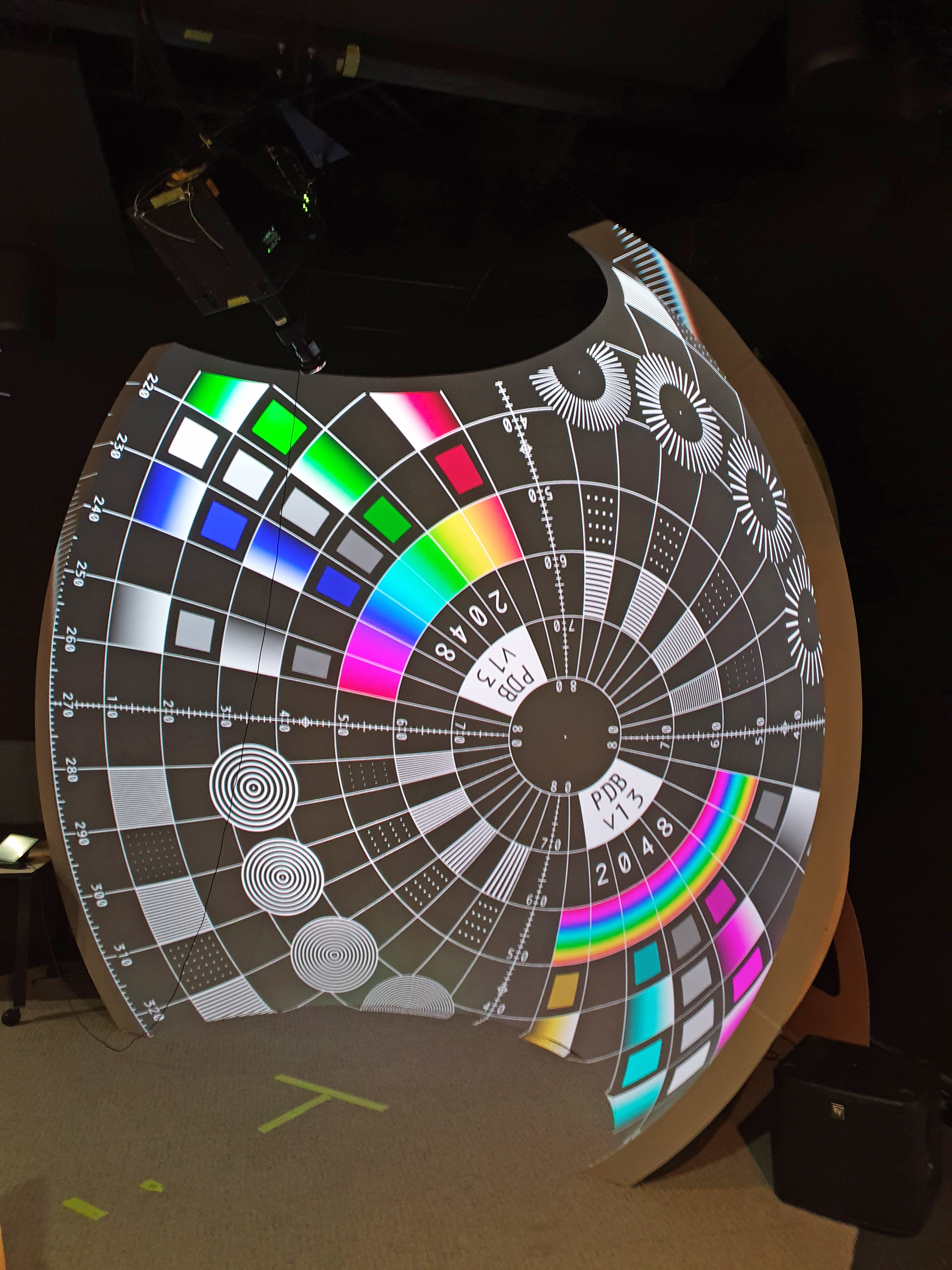
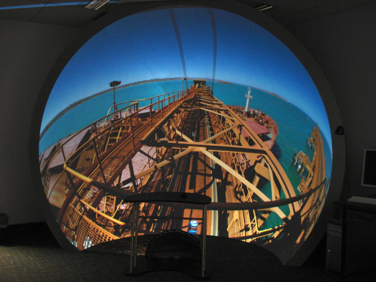
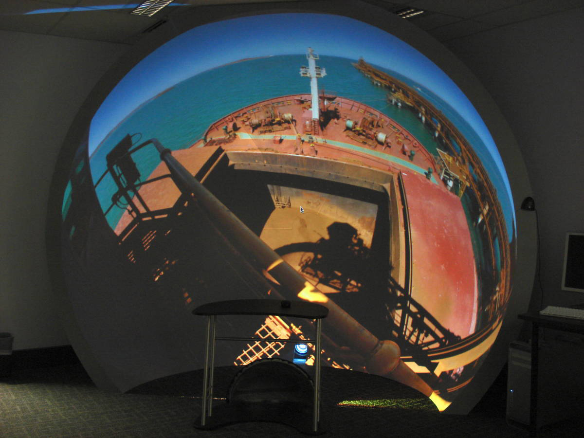
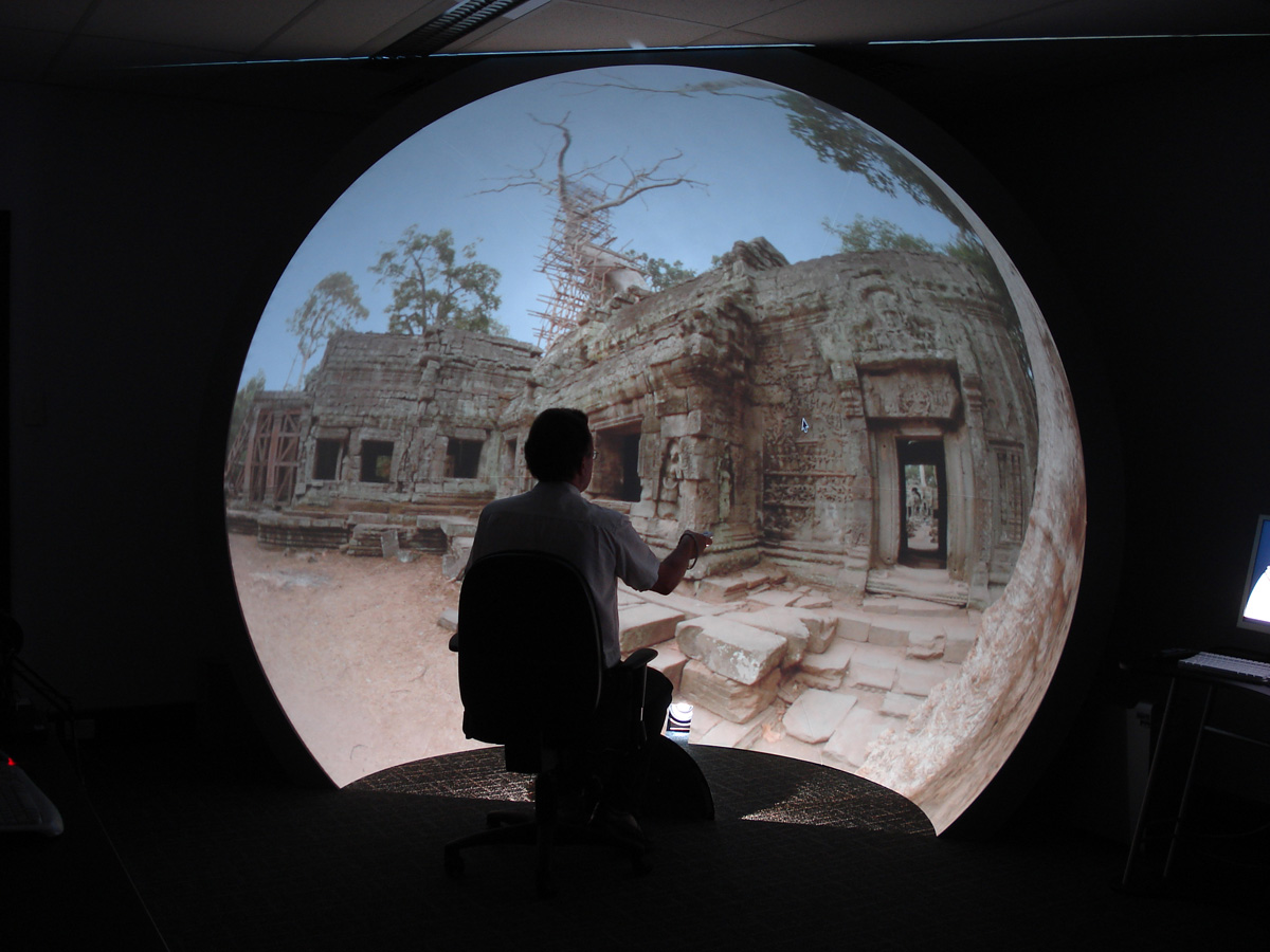
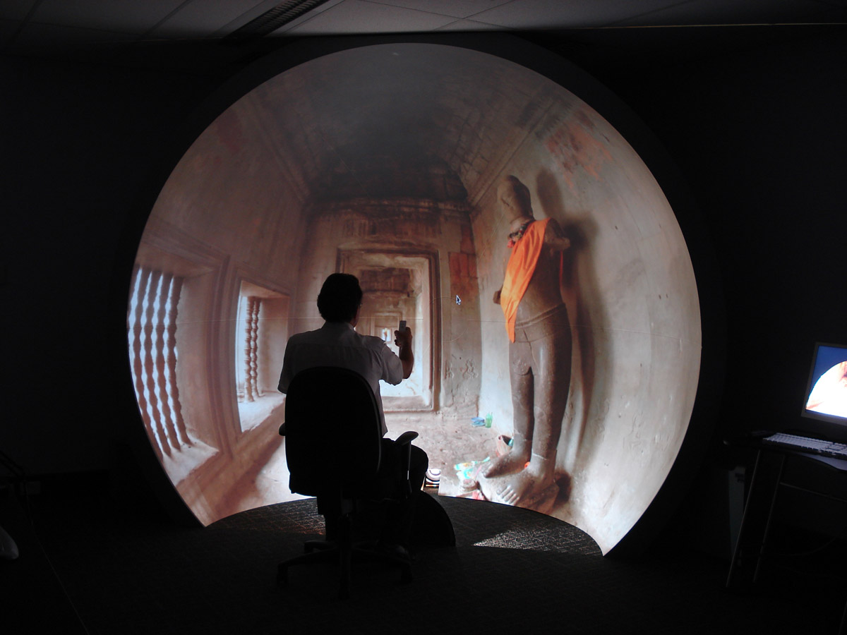
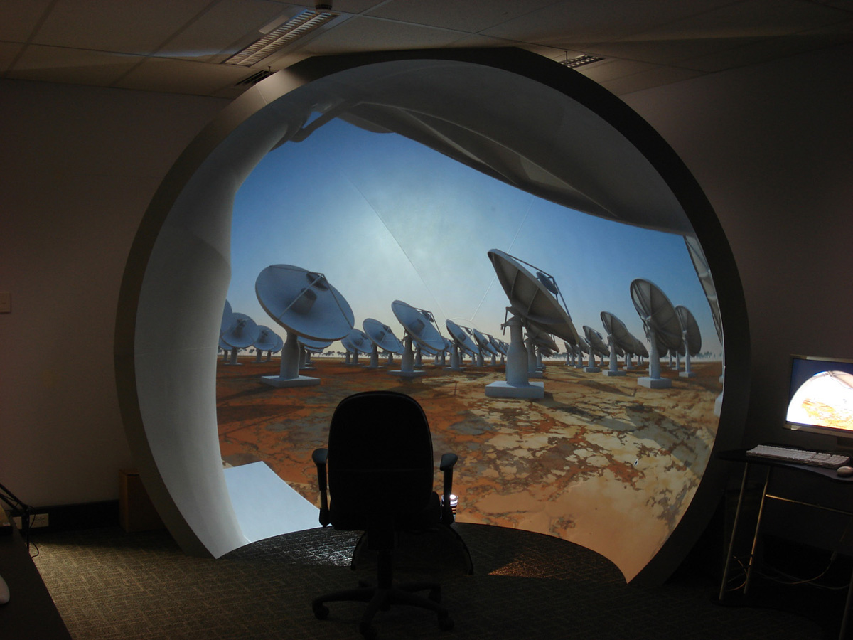
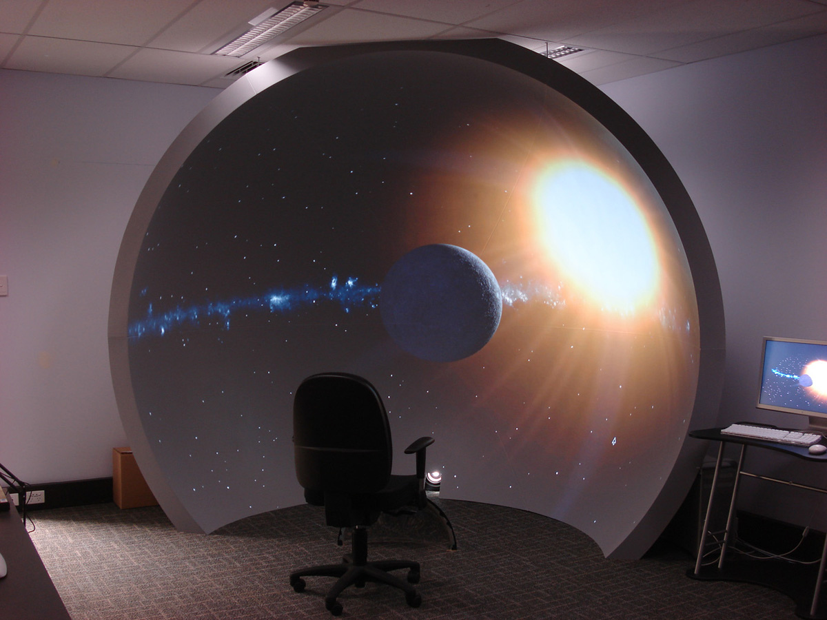
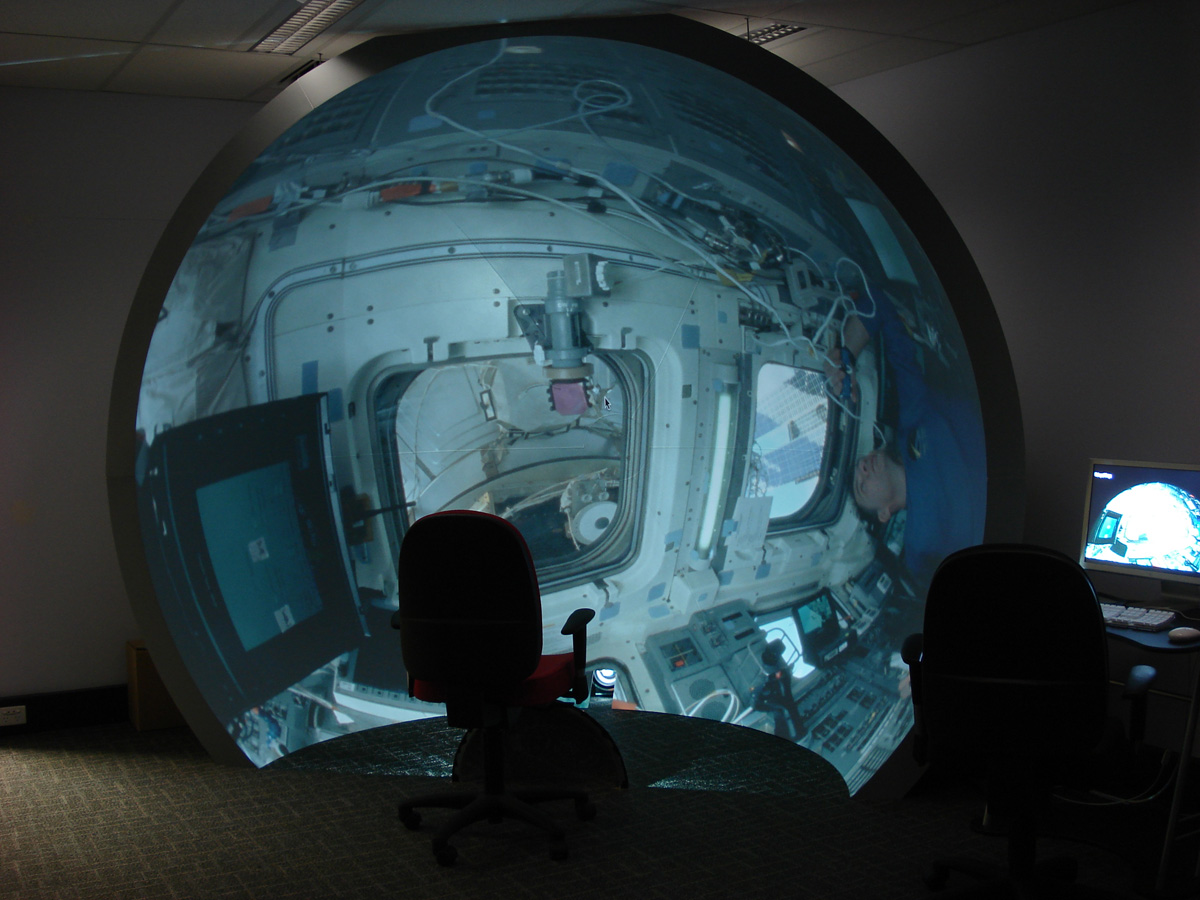
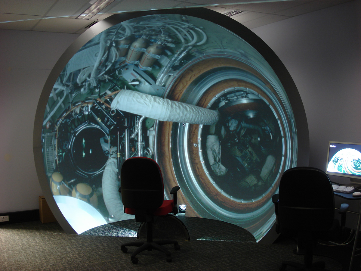
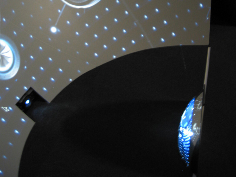
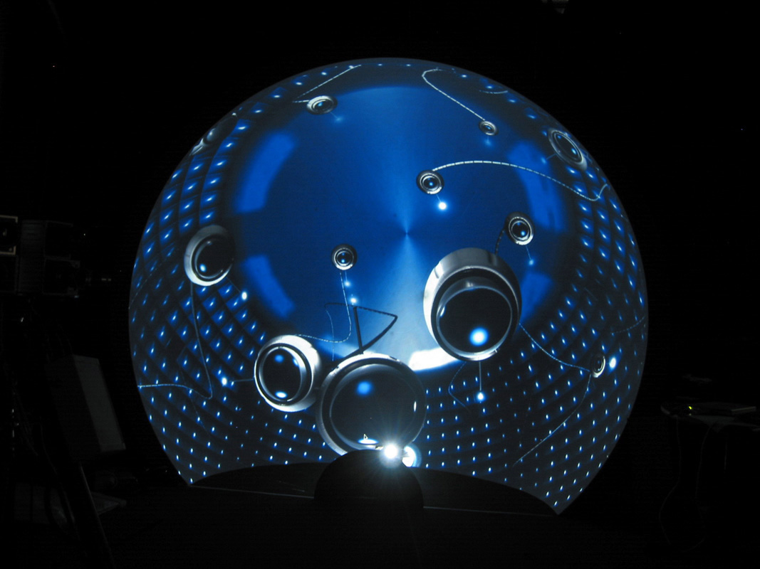
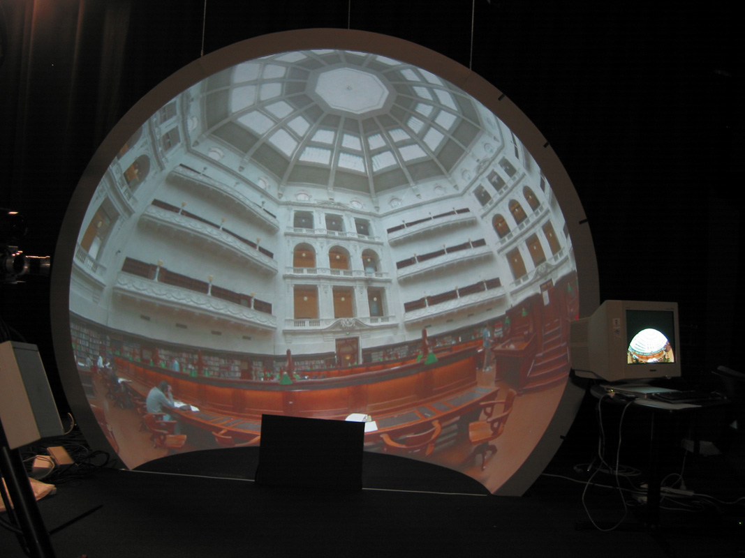
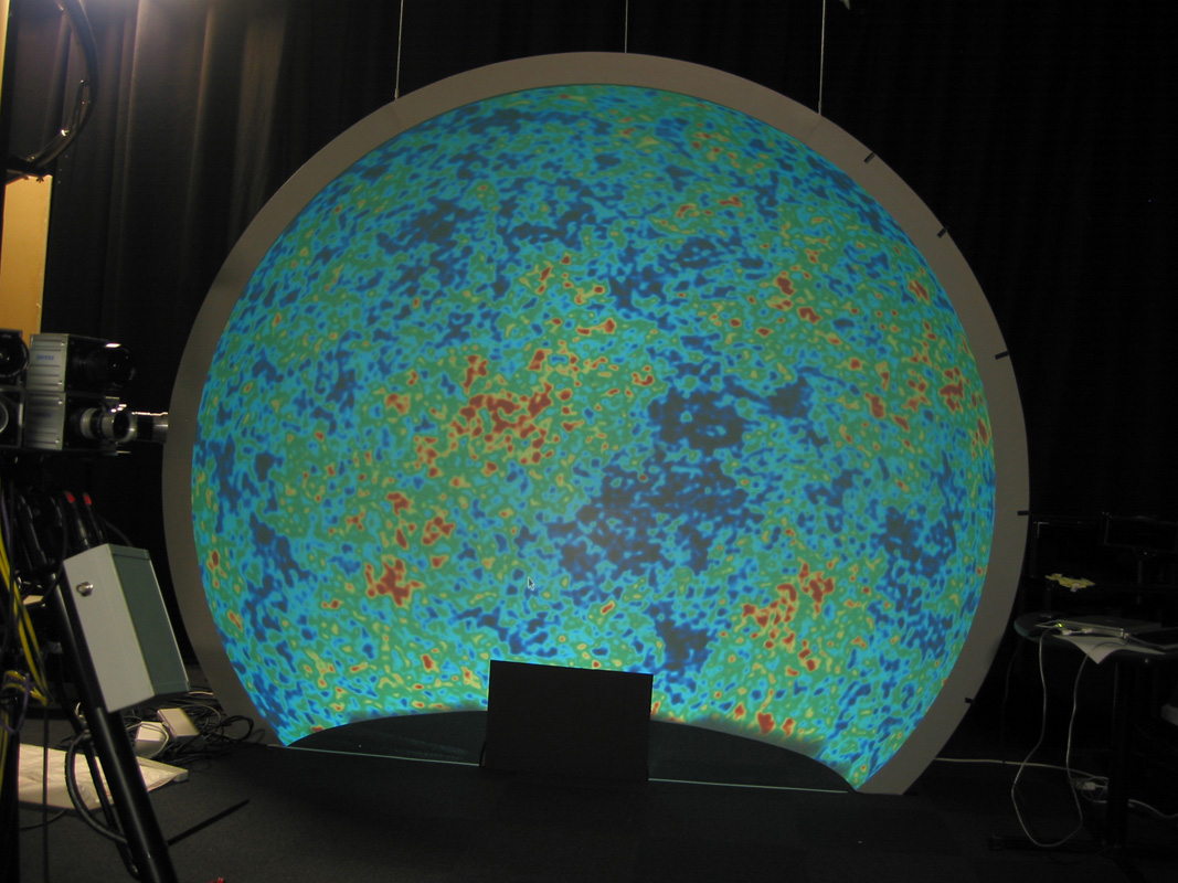
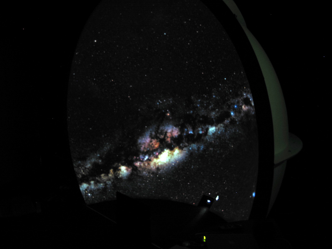
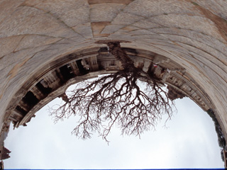
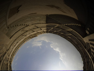
Real demonstration
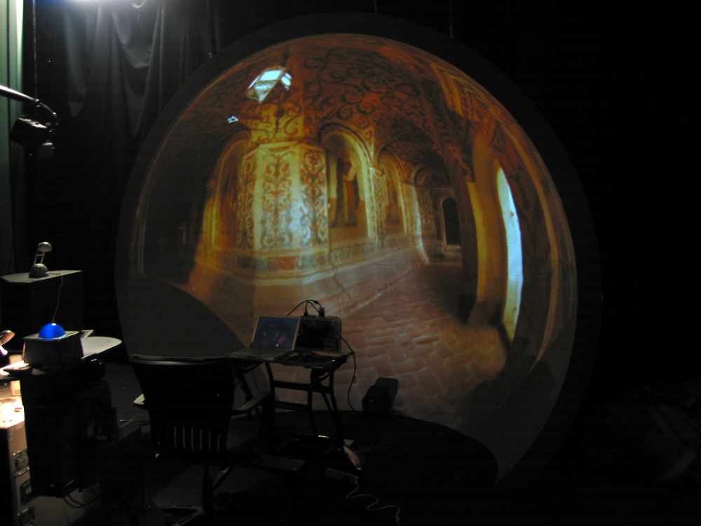
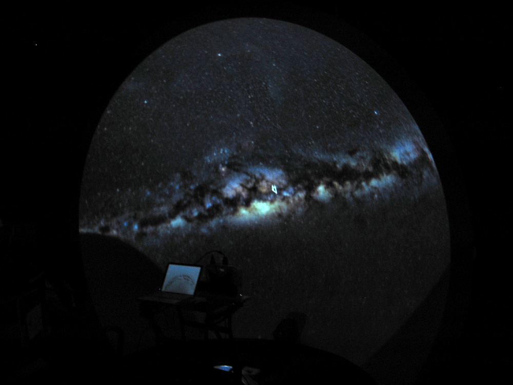
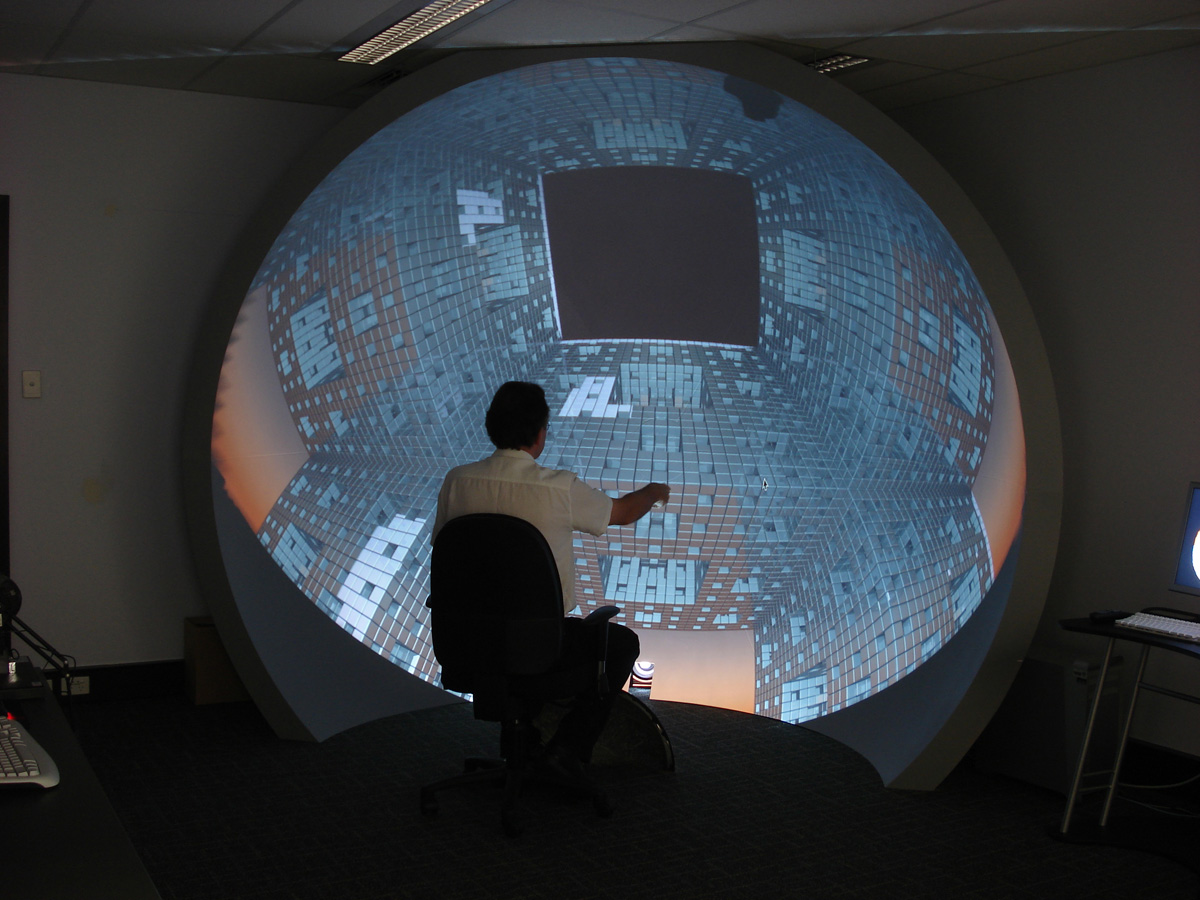
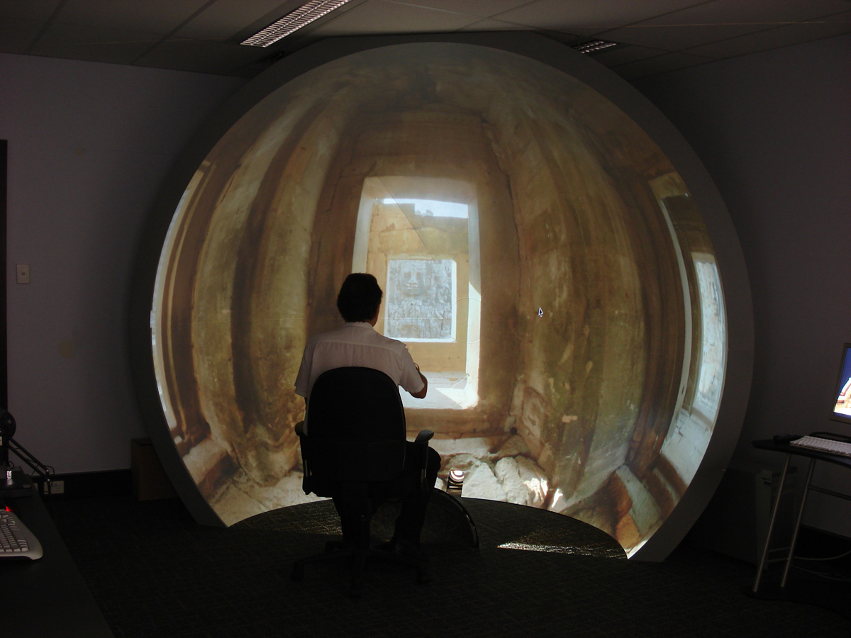
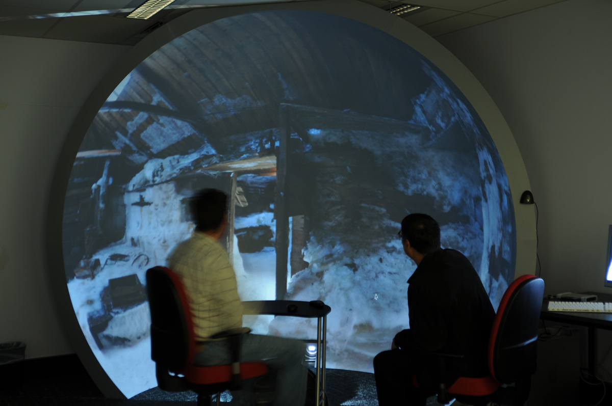
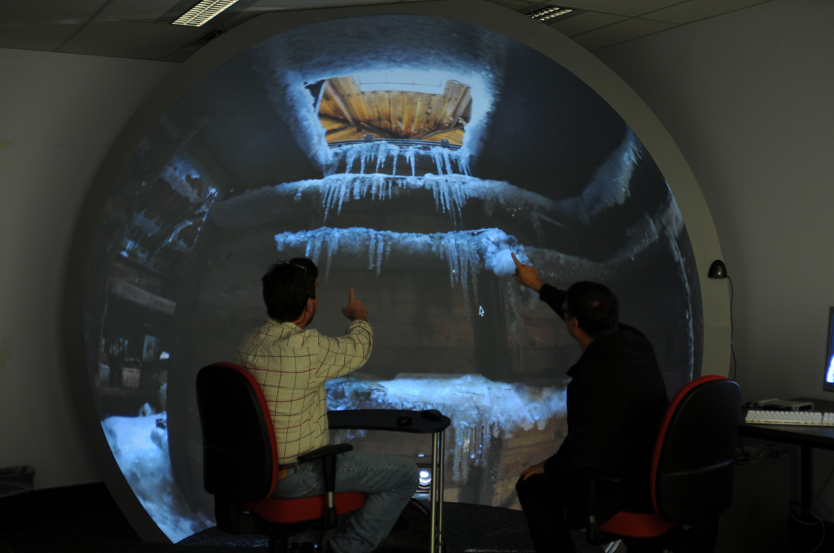
The following show the system in operation on a 3m diameter fibreglass dome. The application is called "panodome" and allows a panoramic, cubic, or spherical map to be interactively navigated, the fisheye and warping is computed in real time on the laptop shown (Mac OS-X). 
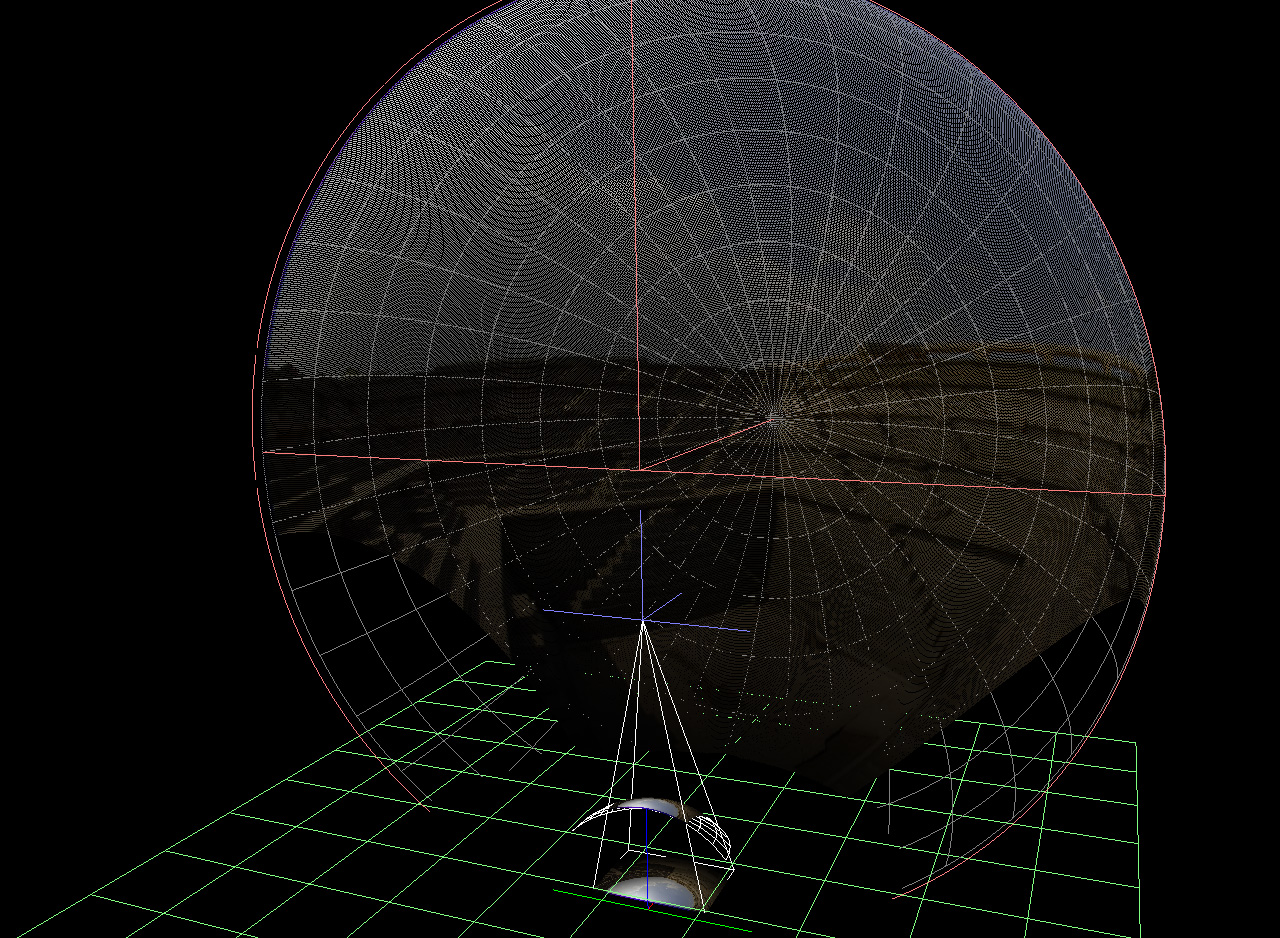
 Optimal mirror shape
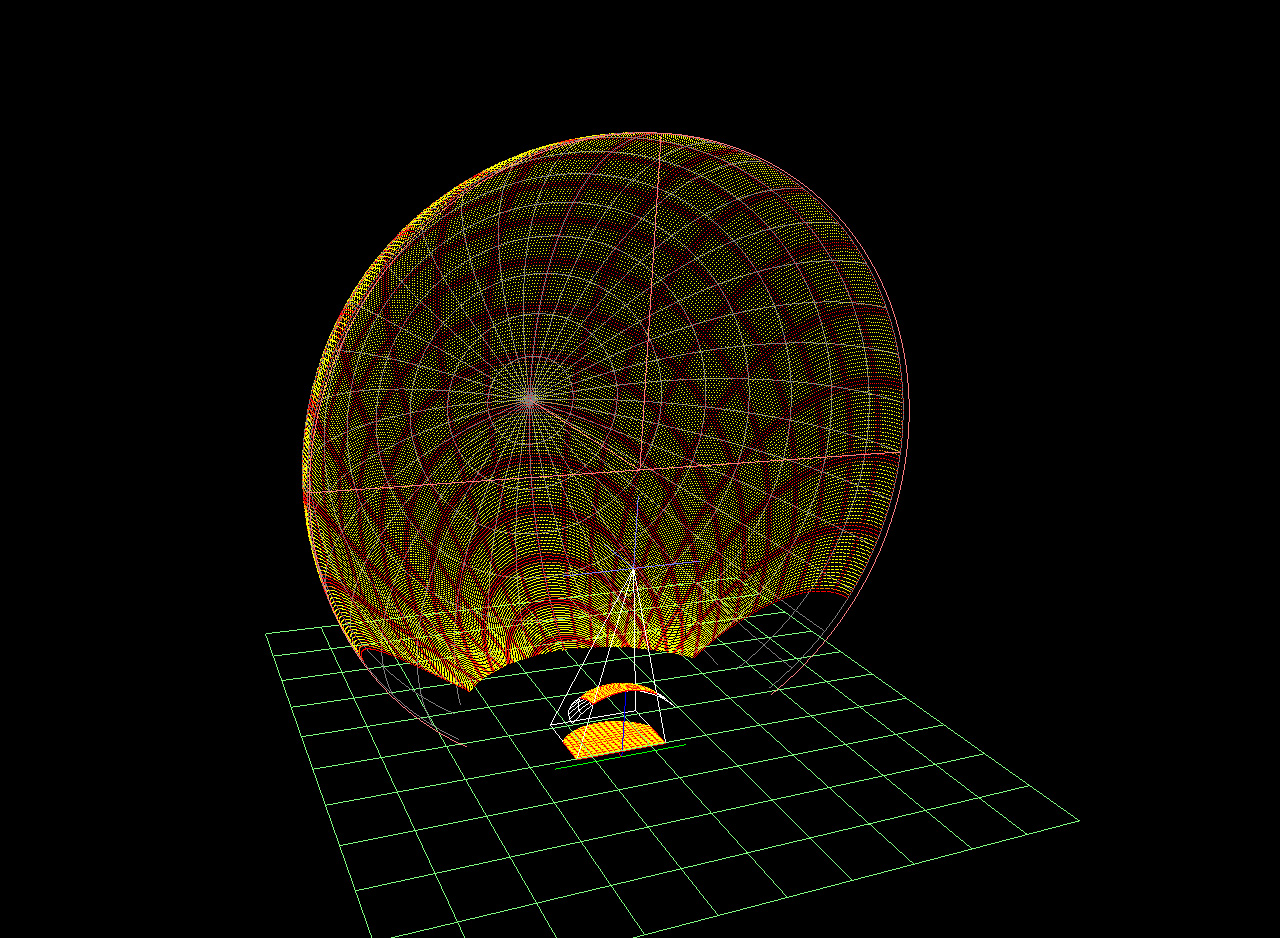
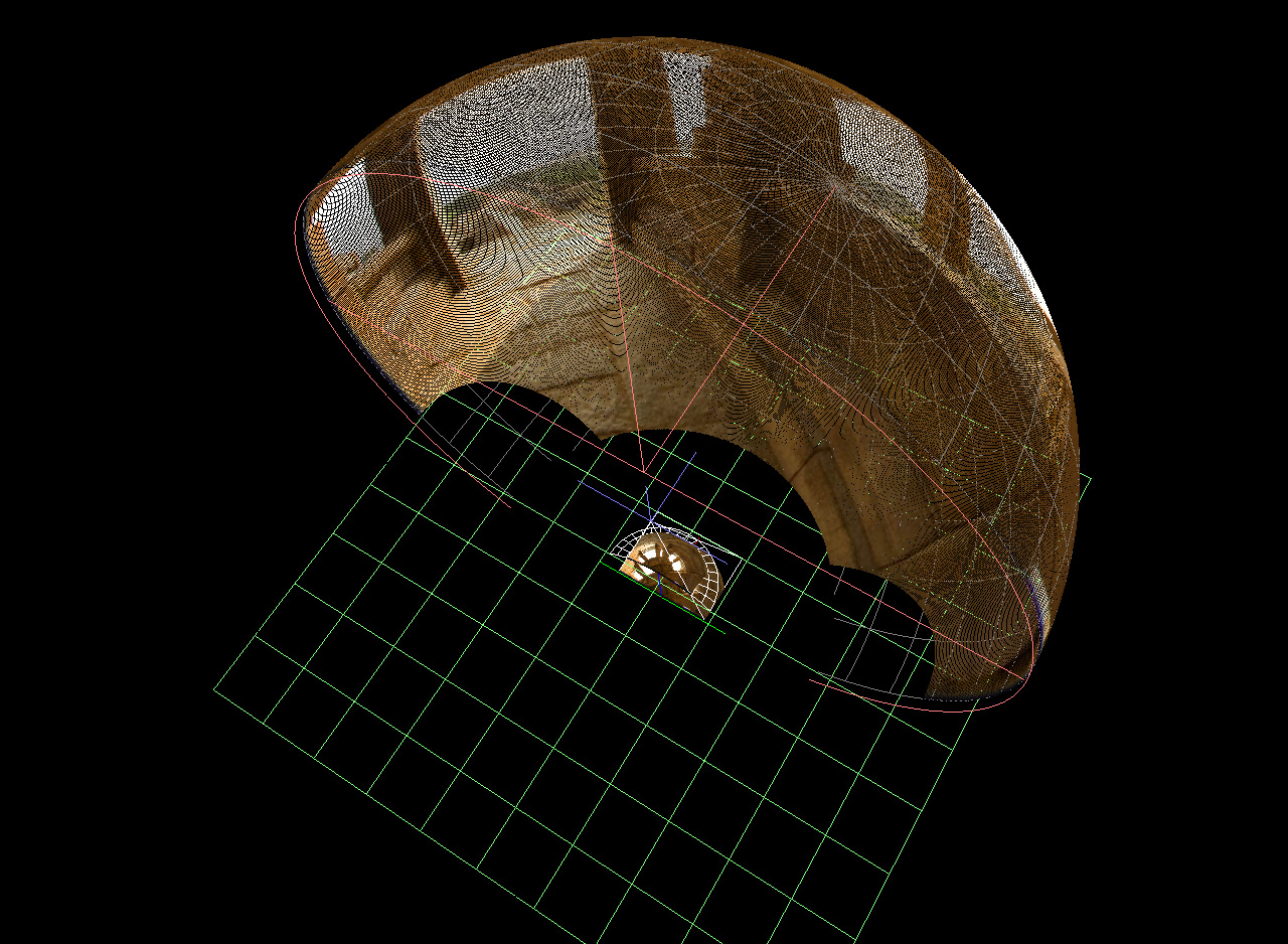
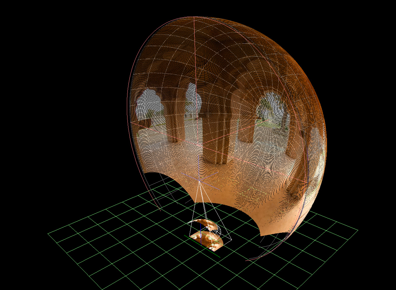
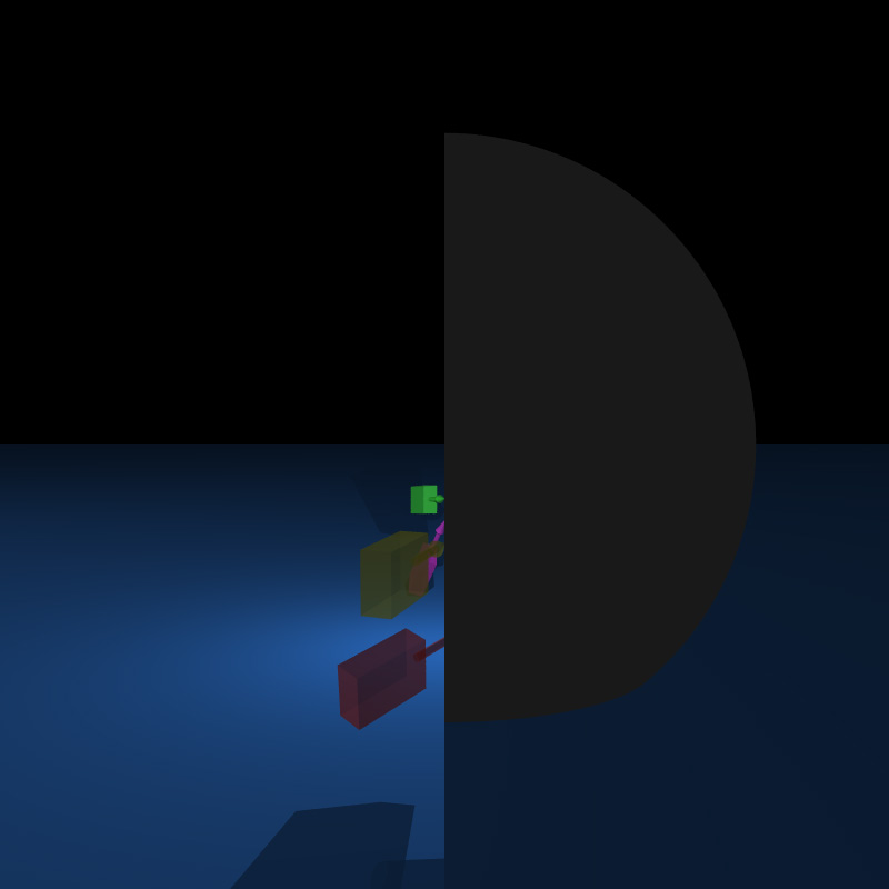
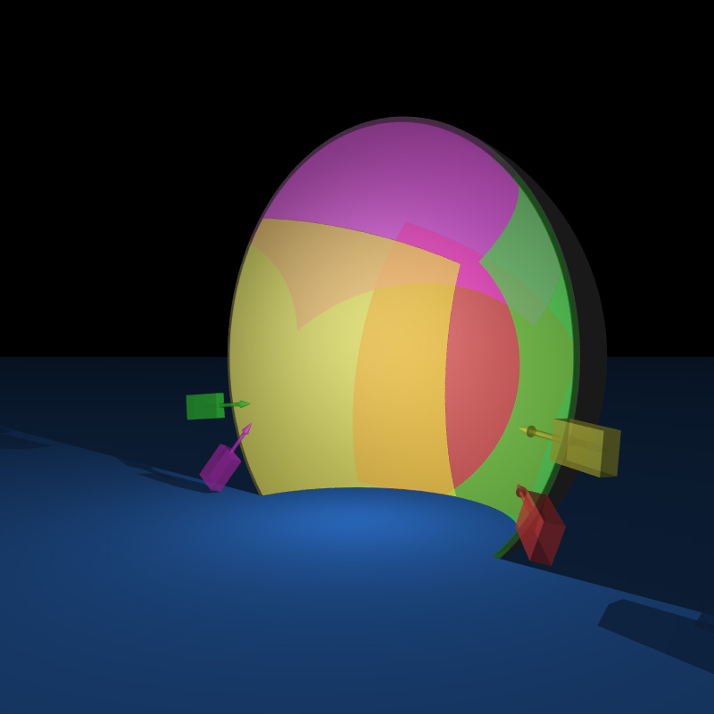
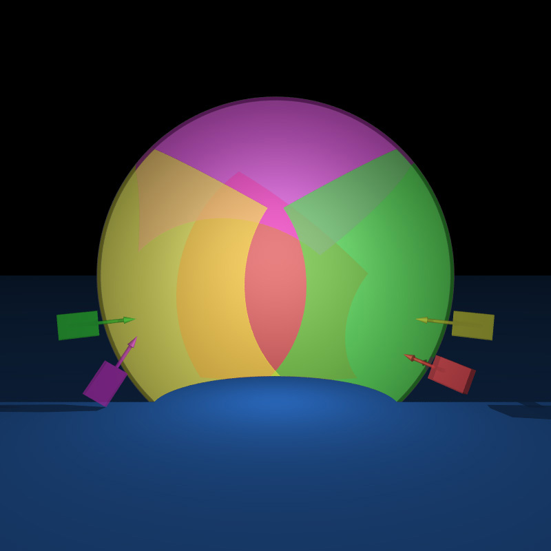
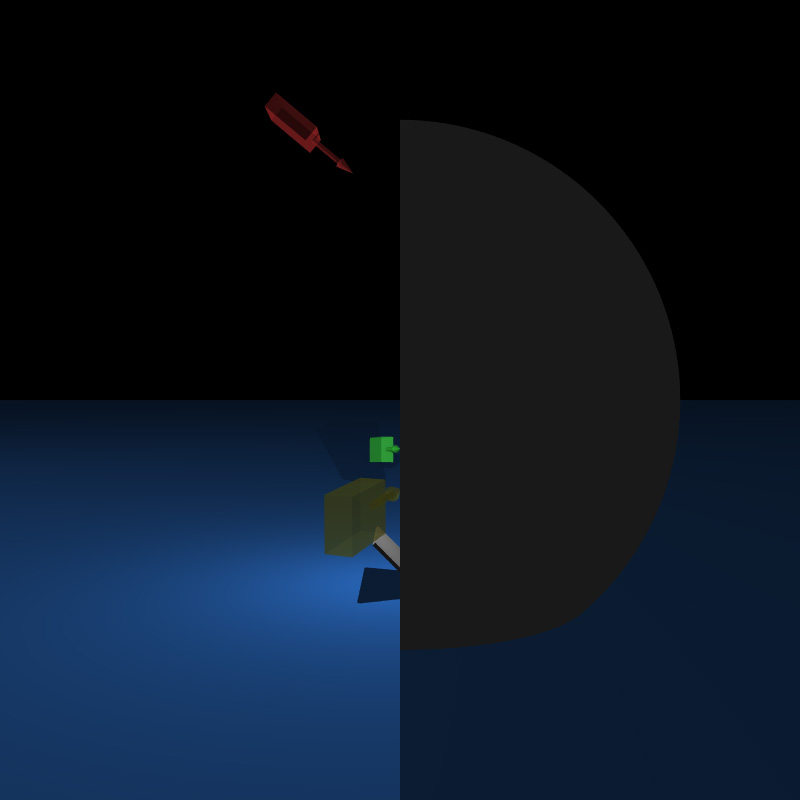
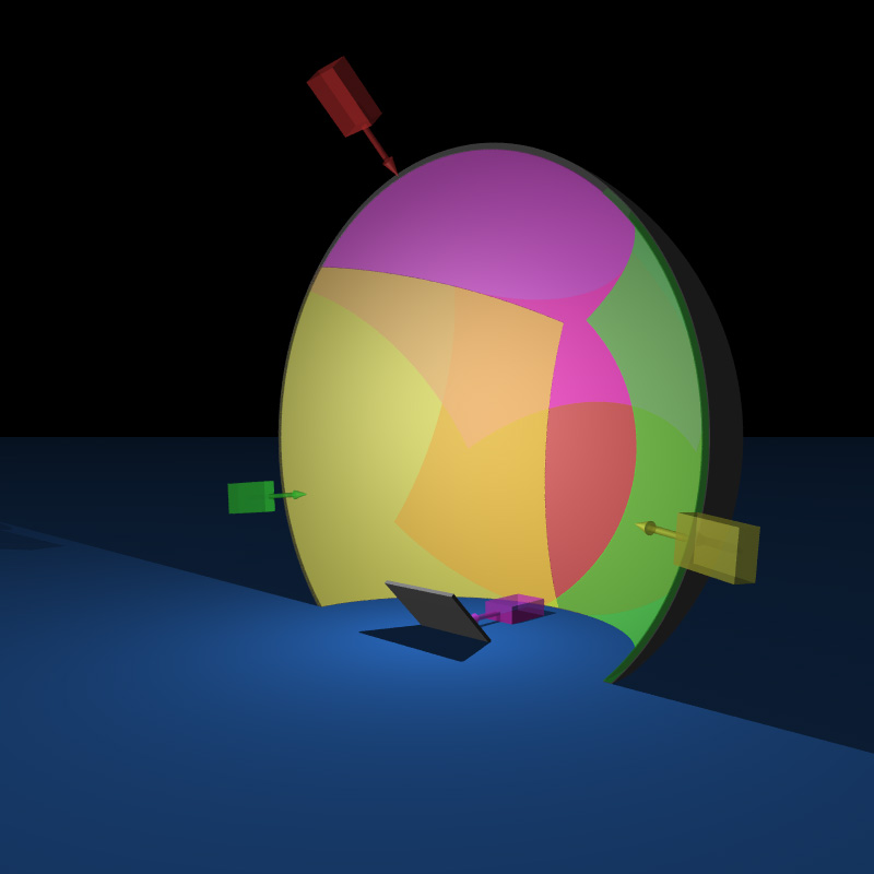
As can be seen by the simulations and photos above, the mirror doesn't reflect light onto the whole dome surface and only a limited area of the projected image is used. One might ask whether there is an optimal mirror shape that both fills the dome and uses as many pixels as possible. As a simpler problem (considered because of the simpler fabrication) is to consider an oblate spherical surface. In the following a raytracing program is used to capture the image on the oblate mirror, the dome is created as a longitude/latitude frame, the camera (red cone) is located where the projector would normally be mounted and camera frustum is arranged to match the projector frustum. 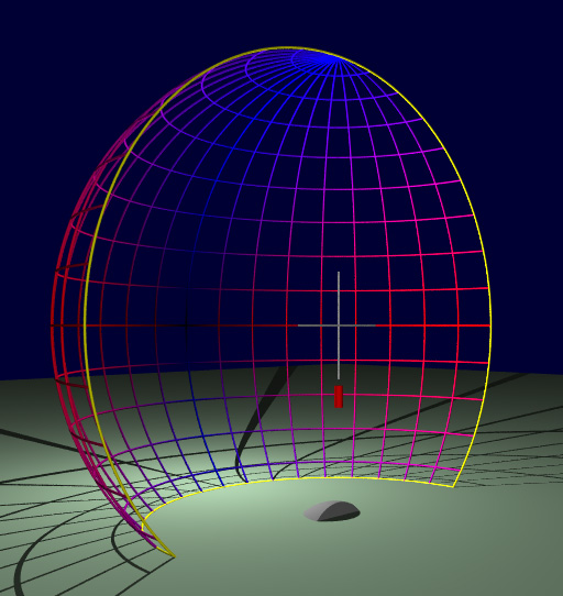
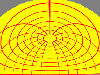
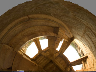
The parameters are carefully chosen to full the dome and maximise the area on the mirror. The image as seen with the camera is shown below. From symmetry if the following image is projected it will fill the dome as shown above. 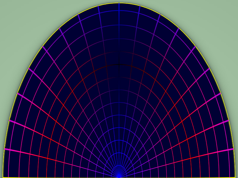
iDome using 4 projectorsWritten by Paul BourkeAugust 2010
The iDome was initial created using a fisheye lens (iCinema, UNSW) and then mostly used a spherical mirror projection. The following illustrates how multiple projectors may be used. One constraint was to limit the number of projectors to 4, this is because 4 projectors can be reasonably driven from a single computer thus avoiding the complications when one moves to a cluster. In the following two cases a 4x3 aspect projector is imagined (eg: SXGA+ [1400x1050]) and the lens employed is a 1:1 throw (distance to width). Asymmetric configuration
| ||||||||||||||||||||||||||||||||||||||||||||||||||||||||||||||||||||||||||||||||||||||


