Converting dual fisheye images into a spherical (equirectangular) projectionWritten by Paul BourkeAugust 2016 See also: Fundamental parallax error when blending images from multiple cameras
The source code implementing the solution below is no longer being offered. There are now much better commercial applications and indeed most dual fisheye camera suppliers are supplying stitching options better than the solution described here, some are even performing it automatically within the camera. Introduction
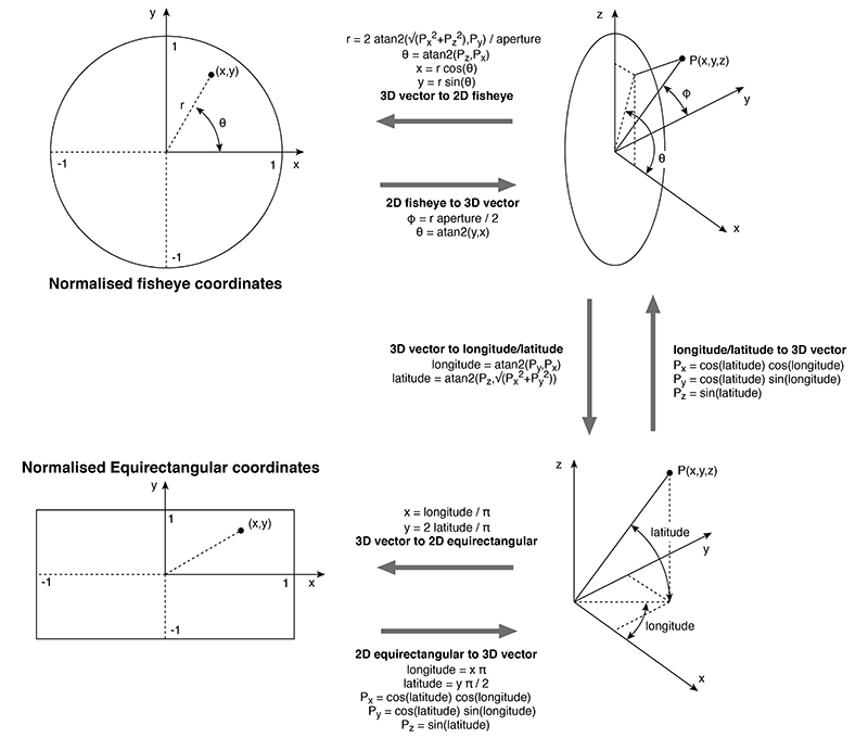
The following presents one method by which two fisheye images, with sufficient apertures, can be combined to form one spherical (equirectangular) projection. It is one of two main approaches, this is a purely geometric algorithm, the alternative is to detect feature points between the two overlapping fisheye images and perform a warp/blend. A "fisheye" image is taken to mean a projection defined as a circular fisheye, namely radially symmetric in longitude and with latitude proportional to the radius from the center of the fisheye circle. Most lenses do have some non-linearity and this is a relatively straightforward correction to make. A fisheye is defined for any angle, 180 being the most common but in the context here one requires greater than 180 degrees. The fisheye circle may be smaller than the image frame it is contained in (sensor size) or it may be larger, so the circle is clipped. Both these situations are common for real fisheye images and camera sensors and as such need to be dealt with. ImplementationThe algorithm described here is tested with a command line utility that accepts various command line option and reads a parameter file describing attributes of the fisheye images. The usage string is as follows. Usage: dualfish2sphere [options] parameterfile Options -w n sets the output image size, default: 4096 -a n sets antialiasing level, default: 2 -b n longitude width for blending, default: 0 -q n blend power, default: 1 -e n optimise over n random steps, default: off -p n n n range search fov, center and rotations, default: 10 20 5 -c s1 s2 input filename, overwrite file specified in parameter file -o s output file name, default: derived from input name -m n specify blend mid angle, default: 180 -f create remap filters for ffmpeg, default: off -d debug mode, default: off The algorithm, as with many of this nature, considers each pixel in the output image and determines the best estimate from the input images. Antialising here is performed using a simple supersampling approach, each pixel in the output image is sampled multiple times at different subpixel positions, the best estimates from the input images are averaged together. For fisheye images greater than 180 degree aperture, the two overlapping halves of their projection into equirectangular space are blended together using a simple linear multiplicative blend function. The parameter file consists of a series of lines consisting of a keyword and value pair. At the very least the file must contain two IMAGE: keywords, the modifier keywords can appear in any order and apply to the previously defined IMAGE:. Noting that the order in which the rotate keywords appear determines the order in which they are performed. An example parameter file is given below, the meanings of the keywords should be clear. A line starting with a "#" is a comment line, the rest of the line will be ignored. All angles are defined in degrees and all coordinates are defined in pixels. # left image IMAGE: sample.tga RADIUS: 904 CENTER: 959 970 APERTURE: 190 ROTATEZ: -1.2 ROTATEX: 0 ROTATEY: -90 # right image IMAGE: sample.tga RADIUS: 904 CENTER: 2879 948 APERTURE: 189 ROTATEX: -2 ROTATEY: 90 In the above the two fisheye images are assumed to be in the same image, one on the left of the other although the algorithm isn't affected by the order. The software also handles the case where the two fisheyes are located within different files. CENTER: defines the center of the fisheye circle (origin is the top left corner of the image). RADIUS: is the radius of the fisheye circle that matches the given APERTURE:. The conventions for a single file containing two fisheye images is given below. 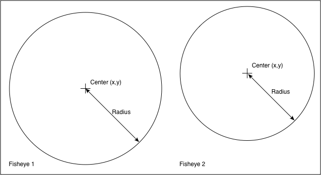
Note the extreme generality of these defining parameters, the fisheye images need not have the same aperture, radius, or position in the image. This is largely to deal with integrated dual fisheye systems that, in the real world, are rarely perfect. For example the lenses are not always on the same optical axis and there is variation between the optics of any two fisheye lenses. The various rotation angles provide a mechanism by which corrections can be made to the fisheye camera/lens system, for example if they don't share the same optical axis. The fisheye lens/camera is assumed to be looking down the y axis, so ROTATEY: serves to roll the fisheye. The x axis is assumed to be to the right, so a ROTATEX serves to correct for the fisheye tilt. The z axis is up so ROTATEZ: serves to pan the fisheye. Note the since the algorithm operates in reverse (from the output image to the input fisheye) the rotational transformations act in the reverse order to which they appear in the parameter file. Example
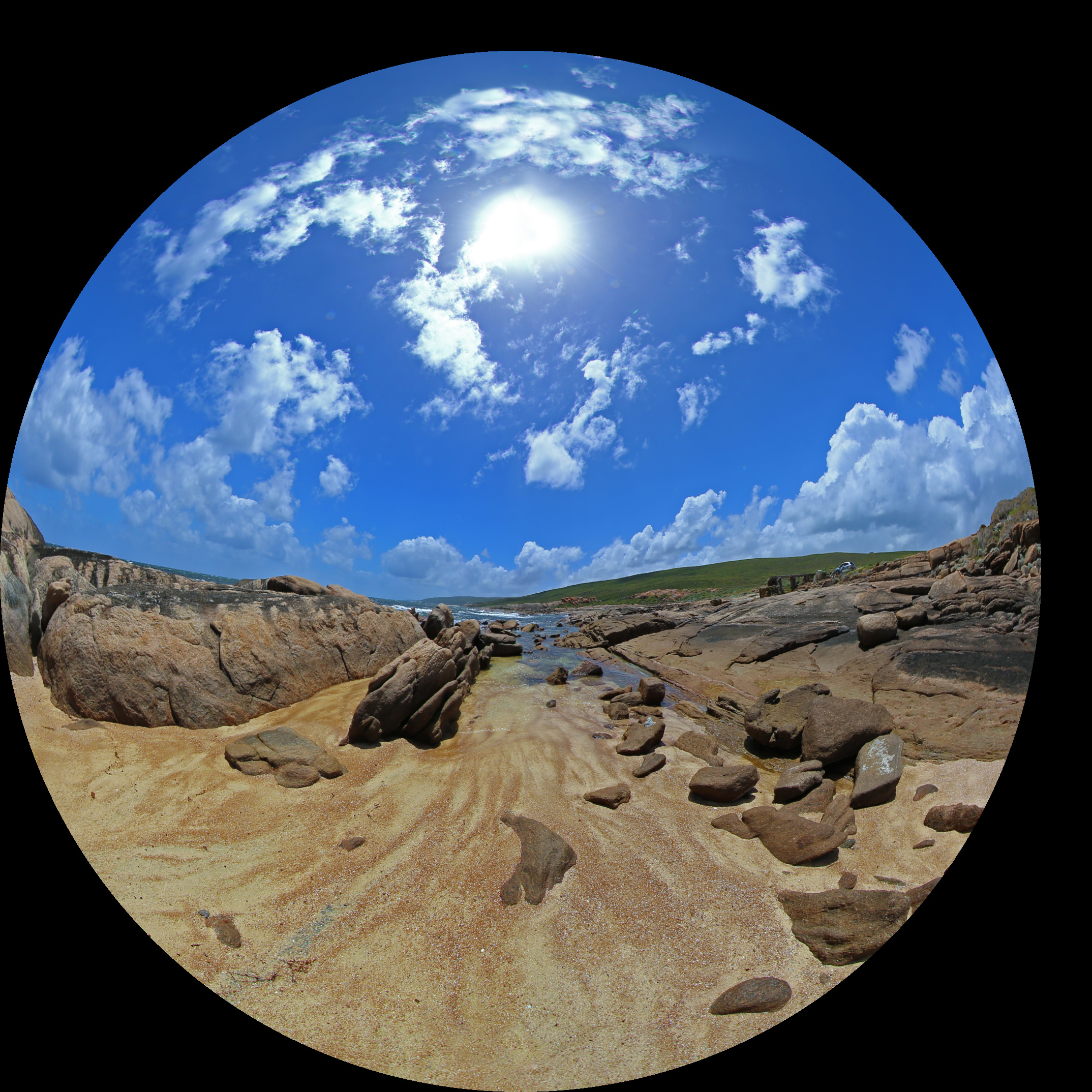
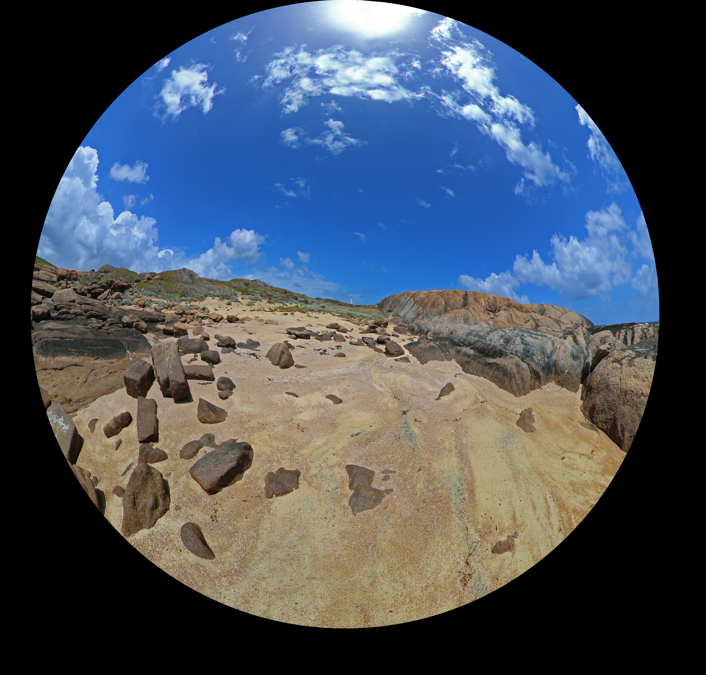
The following example will illustrate the main features of the algorithm implementation. It will be based upon two separate fisheye images, each with an aperture of 210 degrees.
In this somewhat artificial example the left fisheye above is tilted up by 10 degrees. The right fisheye above is rotated clockwise off the optical axis by 5 degrees. The parameter file is given below. # Example for online example # first fisheye IMAGE: exampleleft.tga APERTURE: 210 RADIUS: 1024 CENTER: 1024 1124 ROTATEX: -10 # second fisheye IMAGE: exampleright.tga CENTER: 1124 1024 RADIUS: 1024 APERTURE: 210 ROTATEY: -5 Each fisheye is located in a different part of the image (sensor) plane. The resulting panorama after compensating correctly for these camera/fisheye errors is shown below. 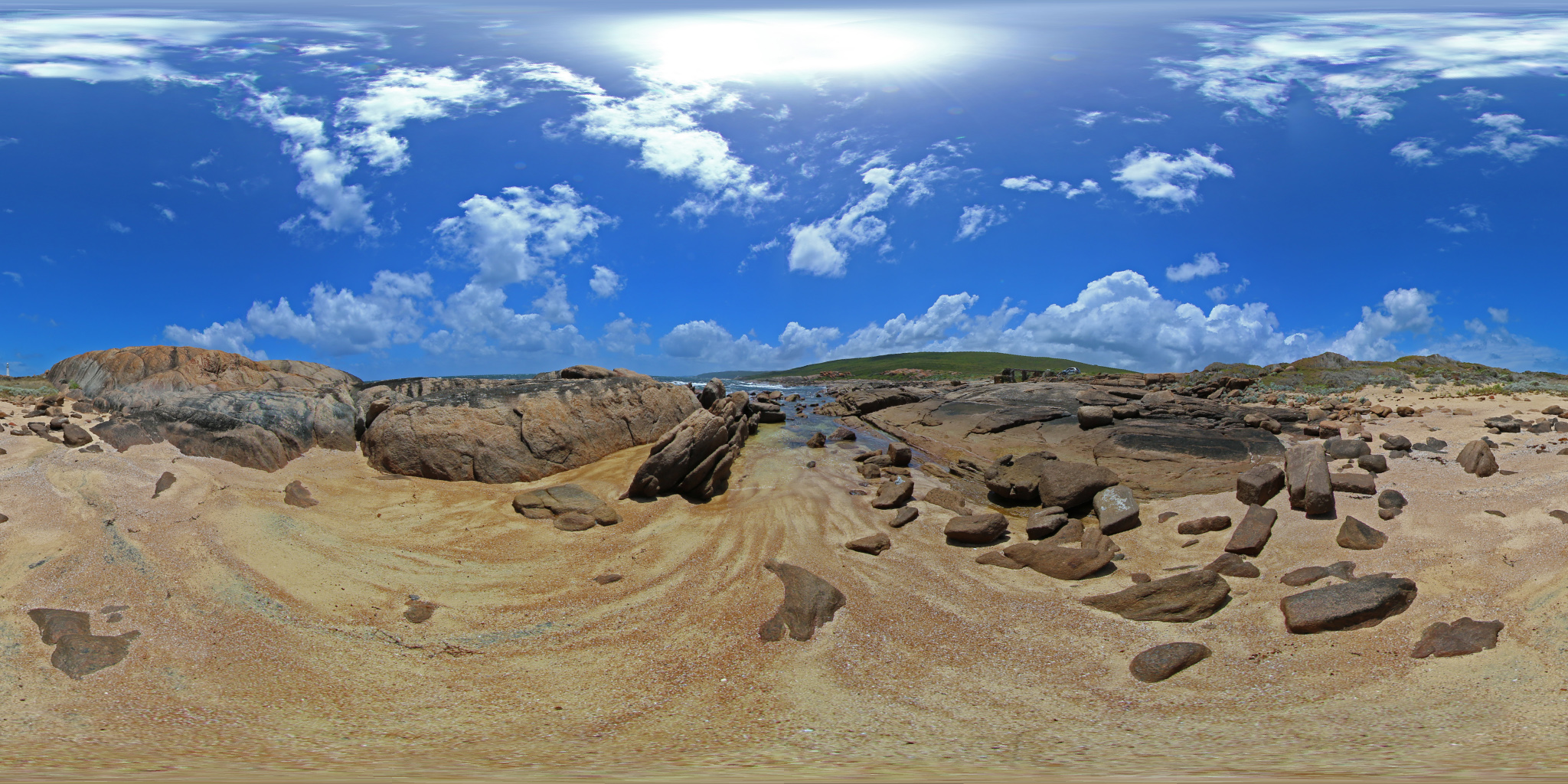
So how does this work? Each fisheye, assuming it has an aperture of at least 180 degrees captures half the visible world, another fisheye pointing in the opposite direction captures the other half. It should therefore be possible to merge the two fisheye images together to form a complete equirectangular projection, which defines the whole visible world. The left fisheye above mapped into equirectangular space is shown below, it fills more than half the equirectangular image because the lens is 210 degrees. Some additional notes and implementation of converting fisheye to equirectangular images can be found here. 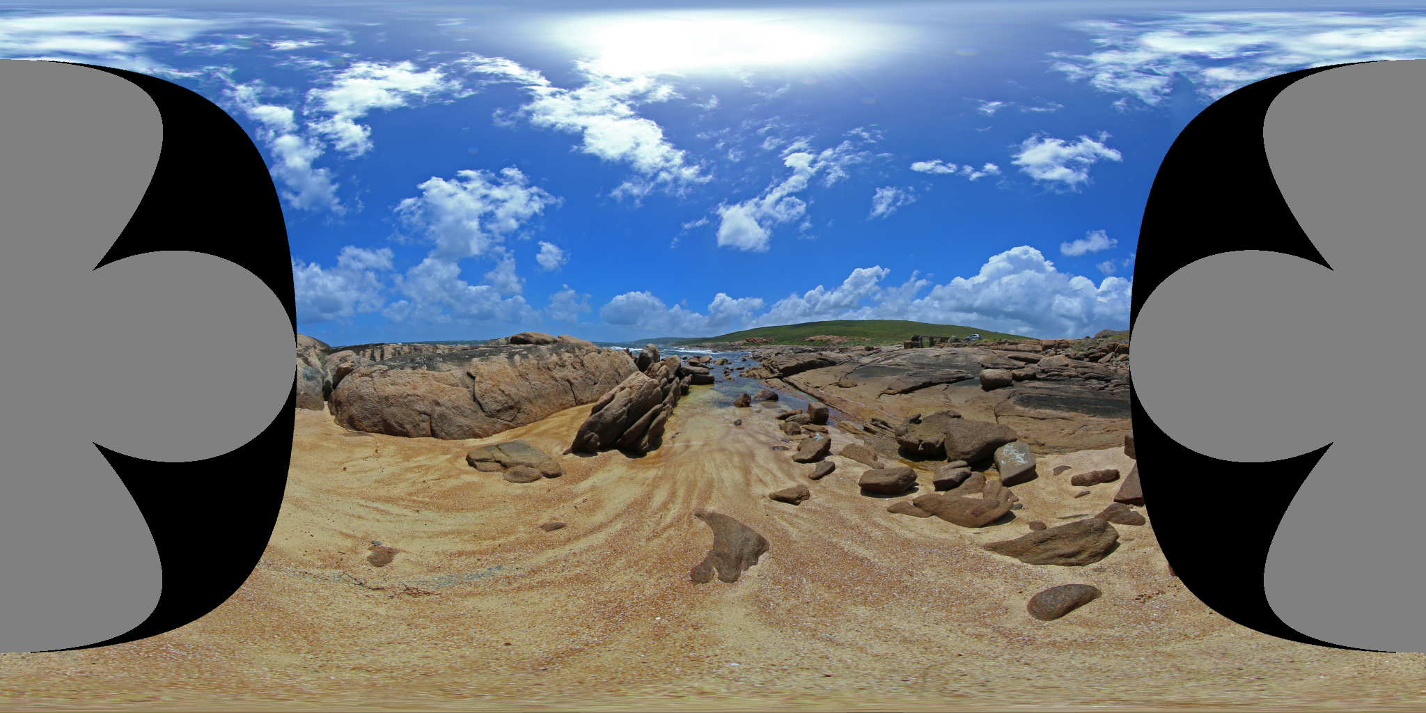
Repeating for the right hand fisheye above gives the following, noting that it generally covers the second half of the equirectangular image and in this case is continuous across the 0 to 360 agle wrap. 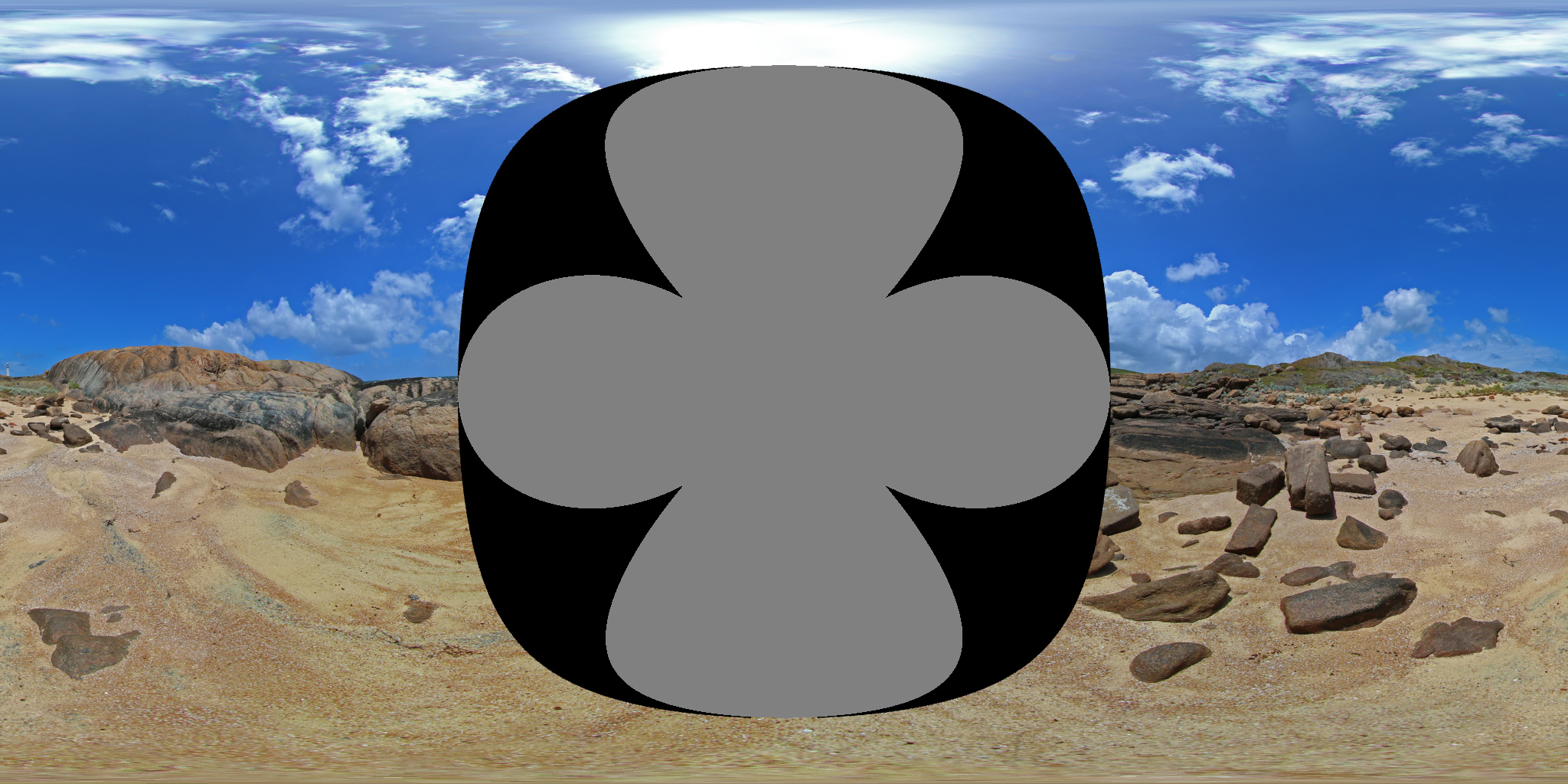
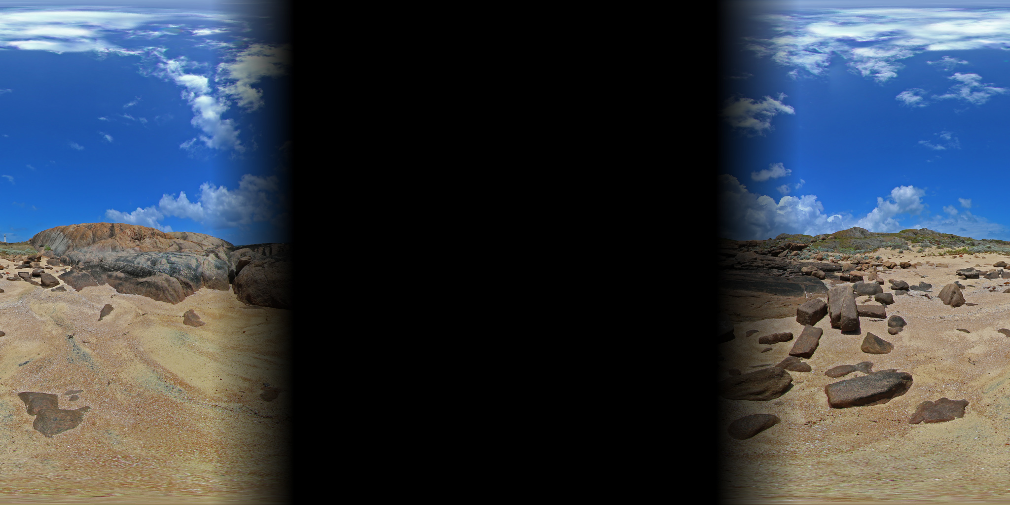
As long as the fisheyes have an aperture greater than 180 degrees there is some image overlap to blend the two halves together. The two images with a blend zone of 15 degrees (75 degrees to 105 degrees) are given below. The final image is achieved by simply adding these on a pixel by pixel basis. 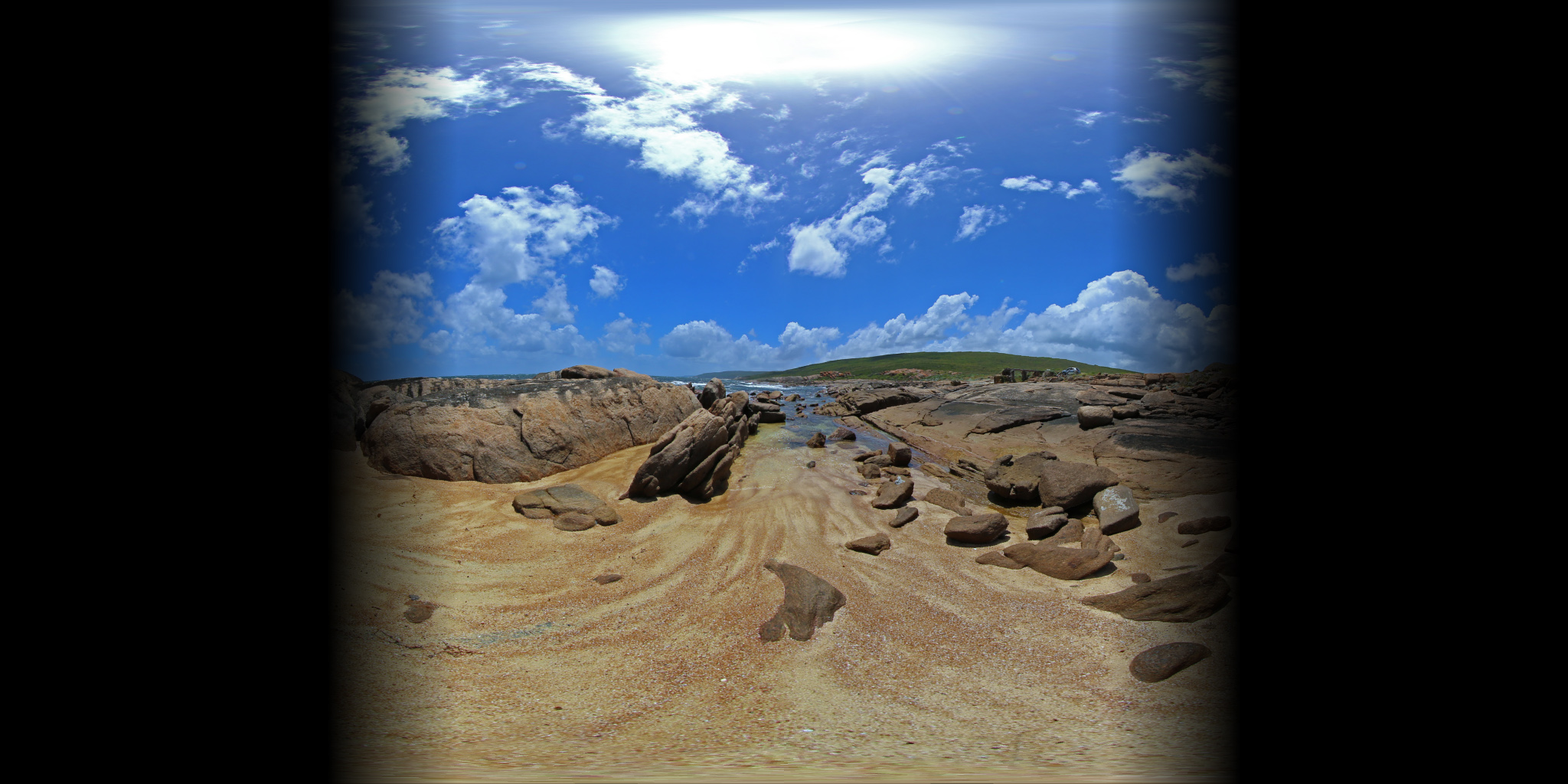
Notes
Automatic optimisation of parameters for dualfish2sphereApril 2017
Described here is an additional utility for dualfish2sphere that, given an initial guess of the parameters, attempts to find the optimal values. Optimal is defined by the parameters that result in the smoothest transition across the two blend zones. The following fisheye pair will be used to illustrate this algorithm. 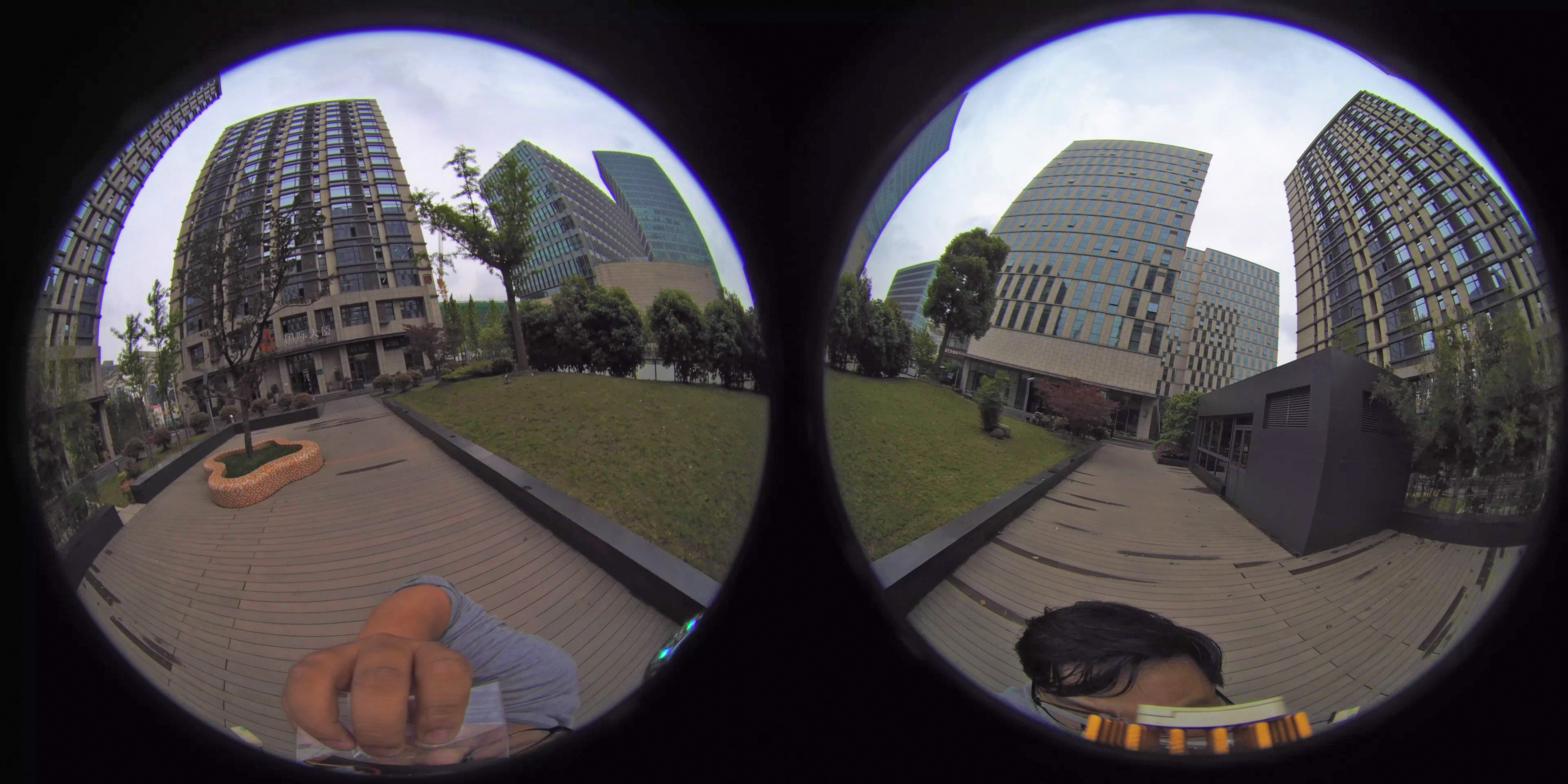
Instructions
1. Estimate the parameters and create the parameter file for dualfish2sphere. The important parameters for the optimisation are the center of the fisheye and aperture. If there are rotations greater than a few degrees, estimate those also. The author generally uses PhotoShop for this, using a combination of the circular selection tool to estimate the position of the fisheye, snapping ruler guides to form the rectangle around each fisheye and the center, and finally the rectangular selection tool and info panel to read off the values of the center. 
The software will randomly search for best fit within a chosen range around the estimates above, the better the estimate the more likely and faster the fit will be found. By default the range of search is +-10 degrees for the aperture, +-20 pixels for the center of the fisheye and +-5 degrees for each rotational parameter. For example, if the estimate of the aperture is 200 degrees, the software will search between 190 and 210 degrees. The range can be adjusted using the -p option. An initial parameter file might be as follows. # left IMAGE: outdoor.tga RADIUS: 905 CENTER: 970 980 APERTURE: 190 ROTATEY: 7 # right IMAGE: outdoor.tga RADIUS: 905 CENTER: 2920 940 APERTURE: 190 ROTATEY: -7 The resulting equirectangular projection is as follows. A blend region of 10 degrees is used, for this example the command line might be dualfish2sphere -w 3000 -b 10 -a 2 outdoor.txt Note the poor alignment in the red ellipse regions. 
2. Run dualfish2sphere in optimisation mode, see -e option. One wants this to run fast so choose a smallish image, say 1000 pixels. Don’t need antialiasing so set that to 1. Must use blending because it is across the blend zone that the error metric works, say 5 or 10 degrees. For example the command line might be dualfish2sphere -w 1000 -b 10 -e 100000 -a 1 outdoor.txtEach time the software finds a better estimate it will save a parameter file. After the requested 100000 steps the best parameter set is given below, note this is in the format of a usual input parameter file for dualfish2sphere. # Optimisation step 22924 of 100000 # Error: 1137.68 # delta aperture: 5 degrees # delta center: 20 pixels # delta theta: 5 degrees # blend width: 10 degrees # image 1 IMAGE: outdoor.tga RADIUS: 905 CENTER: 978 991 # Was: 970 980 APERTURE: 192.3 # Was: 190.0 ROTATEY: 7.0 ROTATEX: 0.3 ROTATEZ: -0.7 ROTATEY: 0.1 # image 2 IMAGE: outdoor.tga RADIUS: 905 CENTER: 2919 950 # Was: 2920 940 APERTURE: 190.0 # Was: 190.0 ROTATEY: -7.0 3. Check that the final parameters of best fit are not close to the range used for the random search. If they are then it may mean you have missed the best value for that parameter. Use the optimal parameter file to create the final image, and subsequent conversions.
dualfish2sphere -w 3000 -b 10 -a 2 outdoor_08.txt
The resulting equirectangular is shown below. 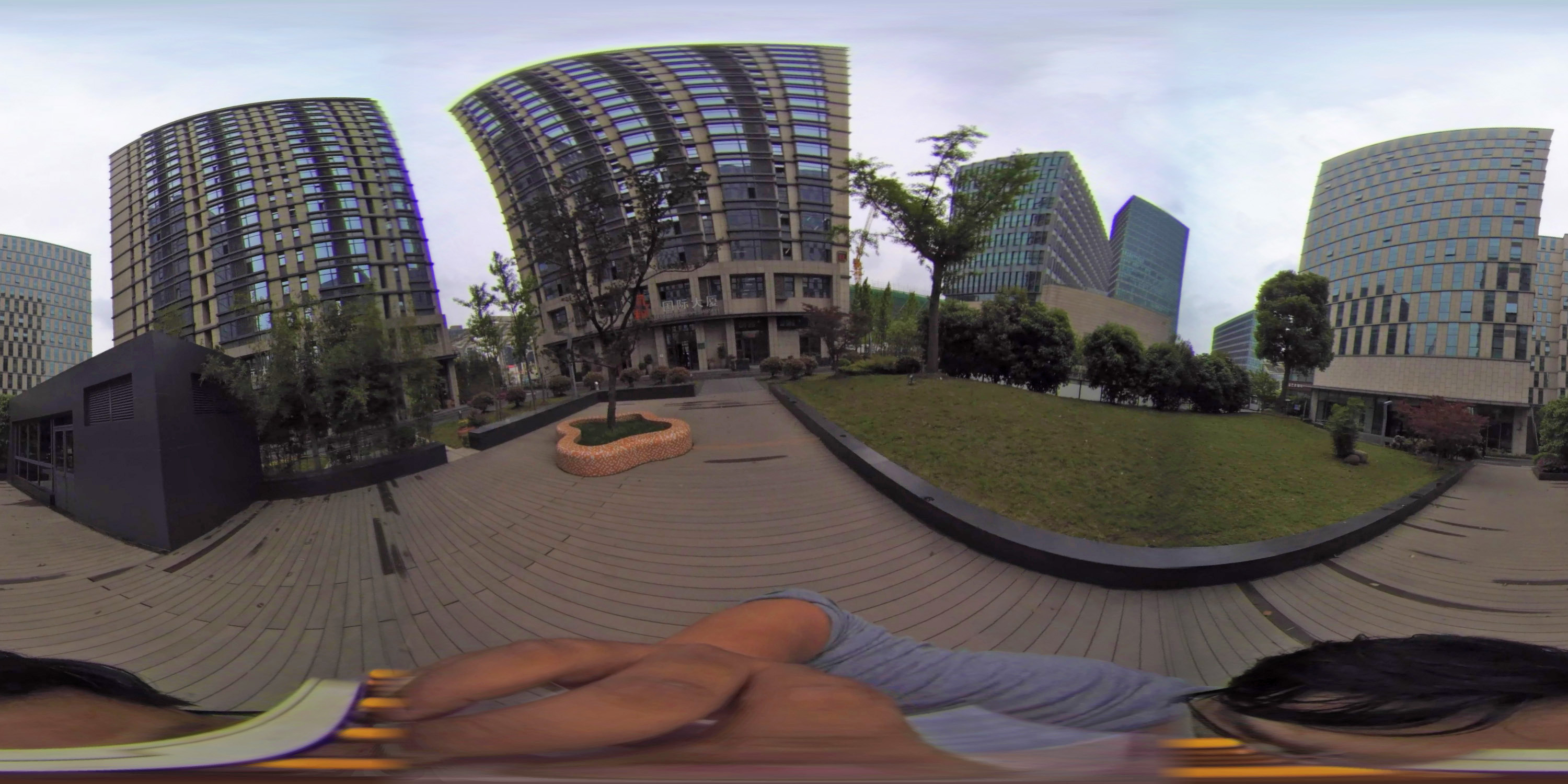
Notes
Remap filters for ffmpegFebruary 2022
The above applies to still image pairs, so in order to convert a pair of movies one needs to extract the frames, convert each one, and then rebuild the movie. The following describes the generation of remap files by dualfish2sphere such that a movie can be converted. The complication is that ffmpeg remap filters are 1-to-1 mappings whereas we require a 2-to-1 mapping across the blend zones. To address this we create two sets of remap files that each convert one of the fisheye image into the corresponding section of an equirectangular. So, for example one might create the remap filters as follows dualfish2sphere -w 3840 -f -b 10 params.txt The two halves, with a 10 degree overlap, can be converted to an equirectangular as follows
   ffmpeg -i front.mp4 -i front_x.pgm -i front_y.pgm -lavfi remap \
      -pix_fmt yuv420p front360.mp4
   ffmpeg -i back.mp4 -i back_x.pgm -i back_y.pgm -lavfi remap \
      -pix_fmt yuv420p back360.mp4
The blend mask can be applied to both equirectangular images as follows. Note that the mask backmask.png and frontmask.png should be the invert of each other and the same dimensions as the equirectangular movies.
ffmpeg -i front360.mp4 -i frontmask.png \
   -filter_complex "[0:v] format=rgba [bg]; [1:v] format=rgba [fg]; [bg][fg]
       blend=all_mode='multiply':all_opacity=1, format=rgba" \
   -c:a copy -pix_fmt yuv420p \
   frontmasked.mp4
ffmpeg -i back360.mp4 -i backmask.png \
   -filter_complex "[0:v] format=rgba [bg]; [1:v] format=rgba [fg]; [bg][fg] \
       blend=all_mode='multiply':all_opacity=1, format=rgba" \
   -c:a copy -pix_fmt yuv420p \
   backmasked.mp4
The frontmask.png might be as follows, the horizontal extent of the blend needs to be less than the blend (-b) chosen in the dualfish2sphere stage. 
And finally the two halves can be combined by adding them together.
   ffmpeg -i backmasked.mp4 -i frontmasked.mp4 \
   -filter_complex "[0:v] format=rgba [bg]; [1:v] format=rgba [fg]; [bg][fg] \
      blend=all_mode='addition':all_opacity=1, format=rgba" \
   -c:a copy -pix_fmt yuv420p \
   combined.mp4
All the above can be added to a single ffmpeg script without the (undesirable) need to generate the intermediate files ... this will be left as an exercise to the reader. |