Manual camera calibration for fisheye image projectionWritten by Paul BourkeMarch 2021
There are two standard ways to project into a dome (or other surface) using a single data projector. The first, invented by the author, is to use a spherical mirror. This has been used in planetariums (some examples here) and is the standard approach for projecting into the iDome. The second approach is to use fisheye optics on the data projector. Unless one can locate the fisheye projector at the center of the dome, both these methods require some image warping in order to achieve the correct result on the dome surface. That is, the content to be displayed is a fisheye image but it is transformed before projection. Creating this transformed or "warped" fisheye can be achieved in a variety of ways. At one end of the spectrum are camera based systems that project known patterns onto the dome which are in turn photographed and the software automatically determines the warping required by knowing the relationship between the input patterns and the perceived pattern. Another approach is to create a simulation of the environment, by specifying and/or manually adjusting the relevant parameters (geometry and optics) one can similarly create the required warp mapping, this is how the authors meshmapper software works. The simulation approach works less well as the free parameters of the system increases, many parameters cannot be accurately measured and manually adjusting a large number is a tedious exploration of a high dimensional parameter space. An example of a parametric approach for a small dome and fisheye lens projection can be found here. For the dome used in this example the simulation approach proved problematic because the dome is not spherical (elliptical) nor does it span 180 degrees (hemispherical). In this case a entirely automated calibration was not required since the hardware is stable, determining the warping required only needs to be performed once. It was decided then to perform a camera assisted calibration but manually digitise the points rather than use machine vision. It should be noted that automatically determining the test pattern points is not the difficult part of the automated systems but rather ensuring each is correctly associated with its corresponding input image position. 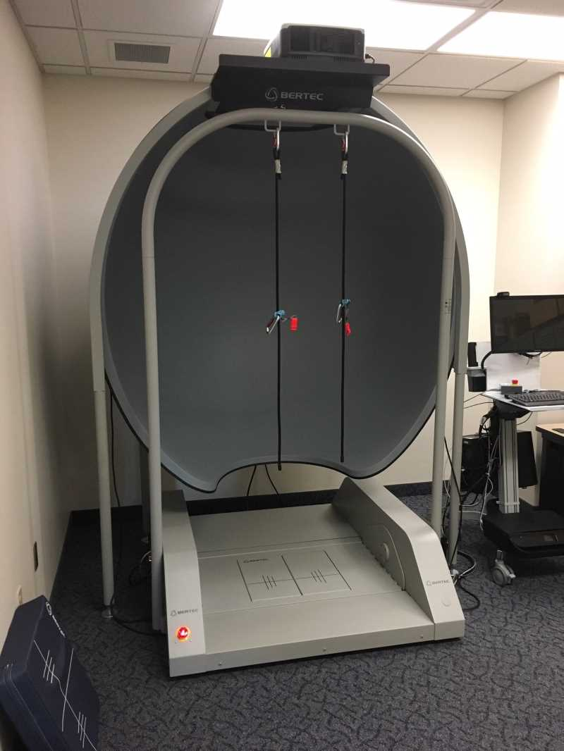
In order to create the warping specification one needs to know where any point in the fisheye image to be projected appears on the dome surface. One way to do this is to project a test image consisting of markers at known positions, in this case coloured dots. 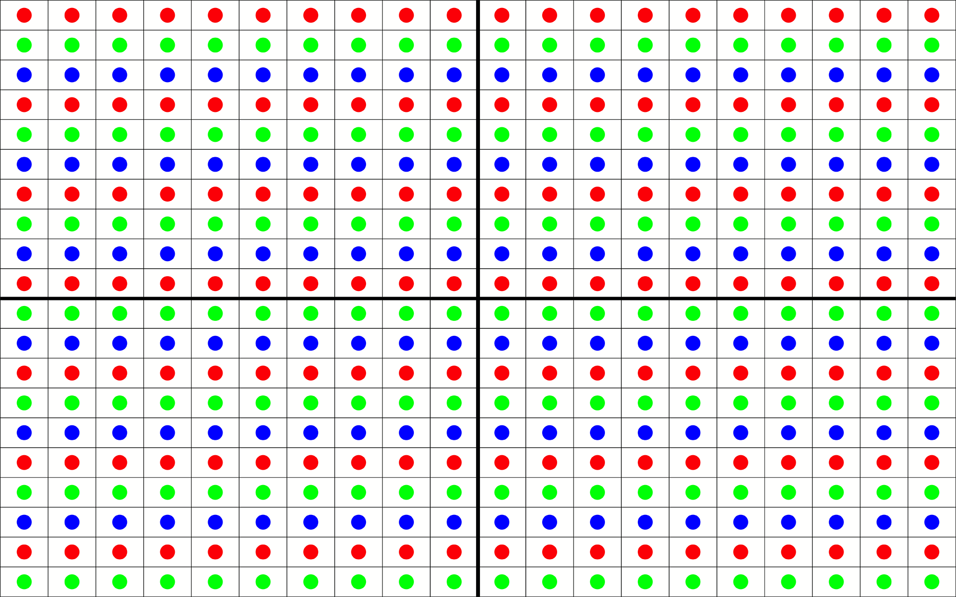
A photograph of the dome is taken from the position the intended viewer will reside, as with all immersive displays, without head tracking, this is the only position for which the final content will be truly correct. For the intended viewer close to the dome this photograph needs to have wide angle optics, typically a fisheye lens. Since consumer 360 cameras are readily available one might use the wide angle optiocs on such a camera. 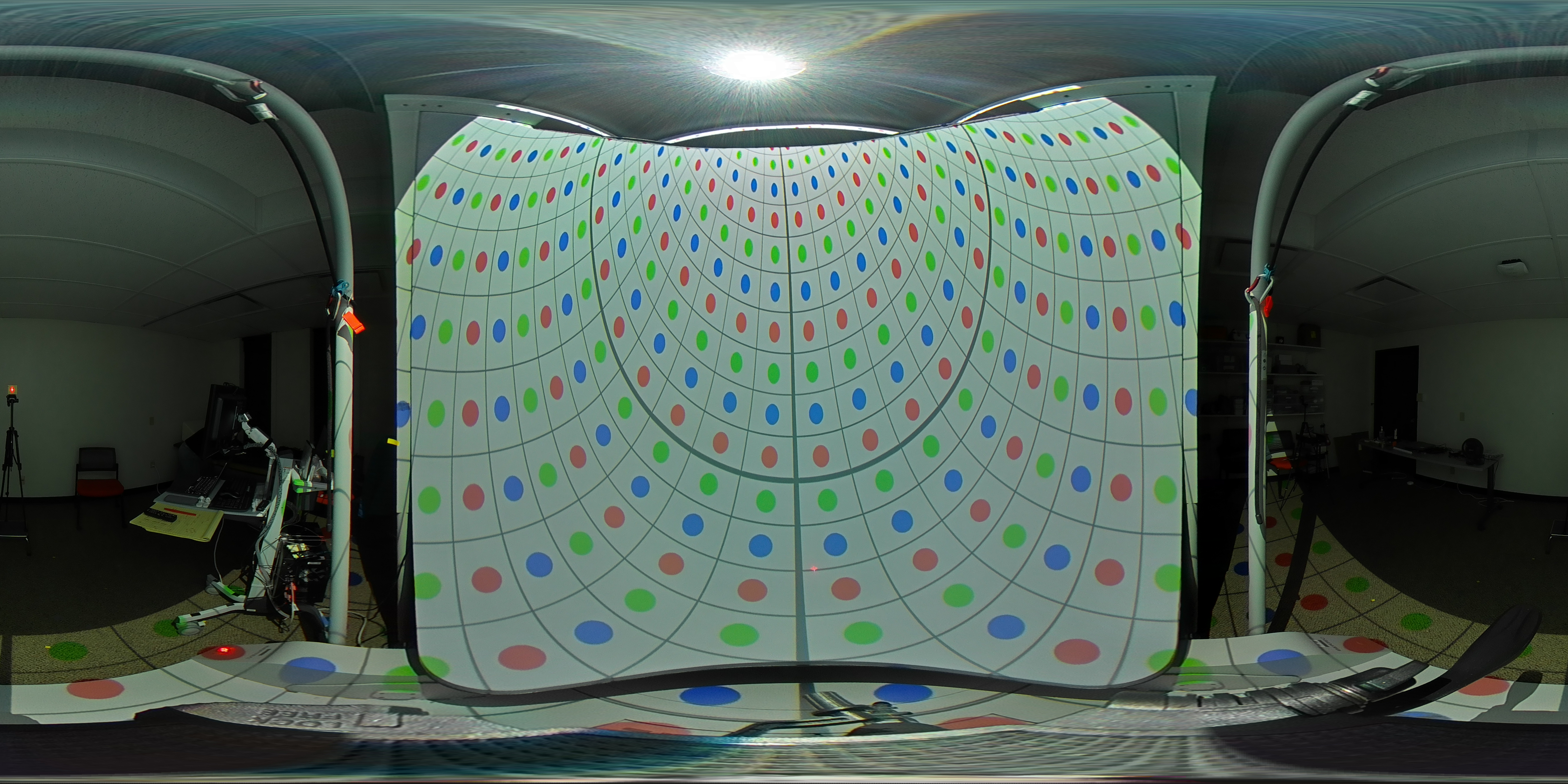

The exact camera used to photograph the dome is irrelevant, as long as the full dome surface is captured and the camera optics are understood. In both cases above using a knowledge of mathematics of fisheye and equirectangular one can calculate the world vector for the center of each dot in the image. In turn for each dot one can determine the (u,v) coordinate in the fisheye image that will eventually be projected. The raw data entered is shown below, the row and column indices correspond to the grid of dot positions in the projected image above. In each cell is the pixel coordinates of the corresponding dot in the equirectangular image. The values of (-1,-1) indicate that the dot in the projected grid does not strike the dome. 
Converting each coordinate pair into their longitude and latitude values creates a longitude and latitude surface. This surface is at the resolution of the table above, which in turn is at the resolution of the original projected grid, in this case a 20x20 grid across the projectors native resolution. 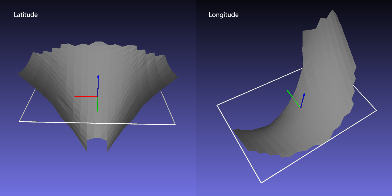
In the following the fisheye test image found here, and repeated below, will be used to illustrate the (x,y,u,v) mesh. The (x,y) regular grid is in the projected image coordinates, as per usual these are normalised to be -1 to 1 vertically and -aspect to aspect horizontally. The (u,v) are the texture coordinates into the fisheye (square) image. 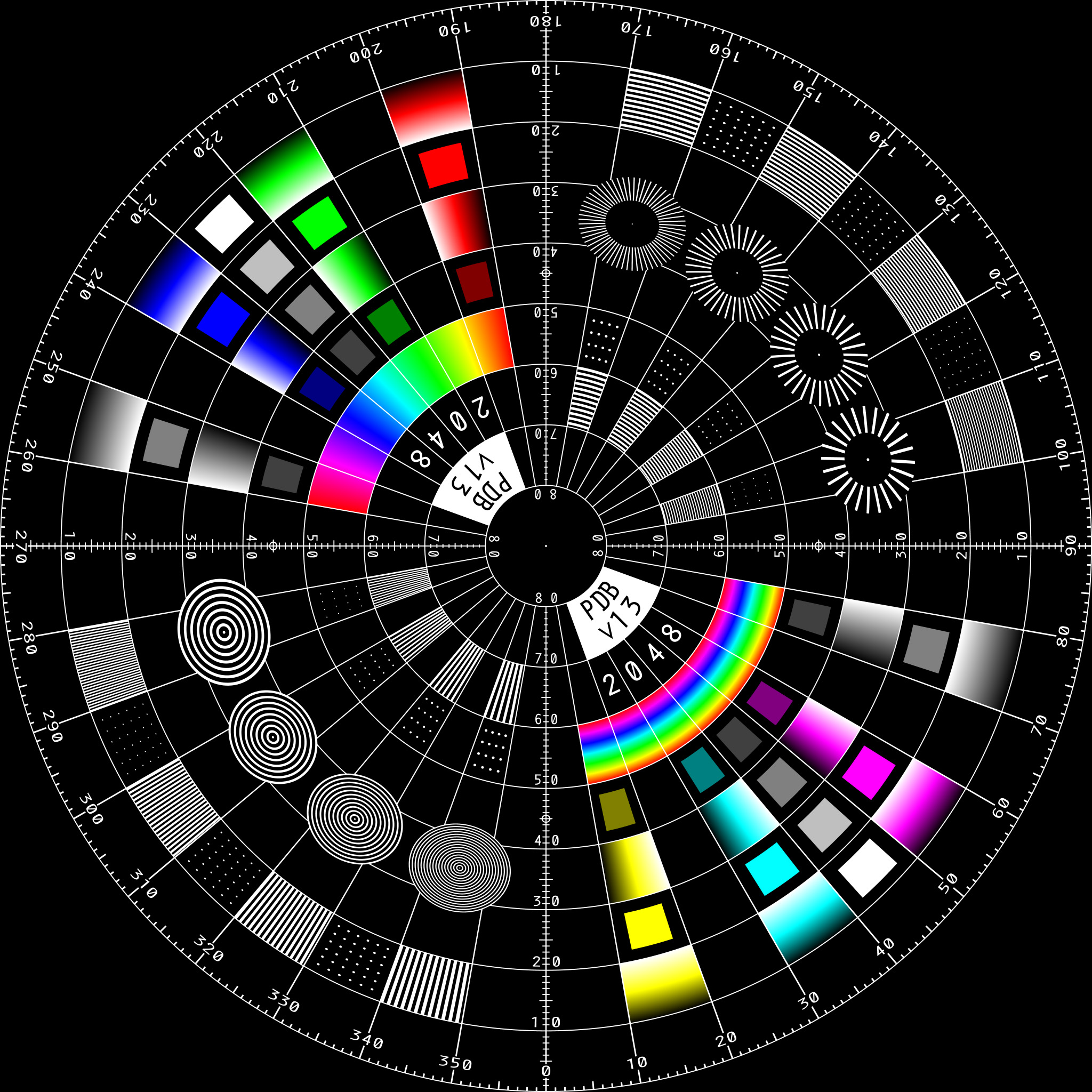
The raw (x,y,u,v) mesh at the resolution of the dot samples is shown below. The interpolation is just the standard OpenGL style texture interpolation between the mesh nodes, so not particularly smooth. 
The longitude and latitude surfaces can be smoothed in a variety of ways and at the same time extrapolated to fill for the gap near the rim of the dome where there were no dots. 
Finally, the smoothed (x,y,u,v) mesh, in this case at a resolution of 160x100 cells. This mesh can be used directly as a (x,y,u,v) mesh in programs like Unity3D, or as the data for a suitable shader, or it can be computed on a per pixel basis for other delivery solutions. 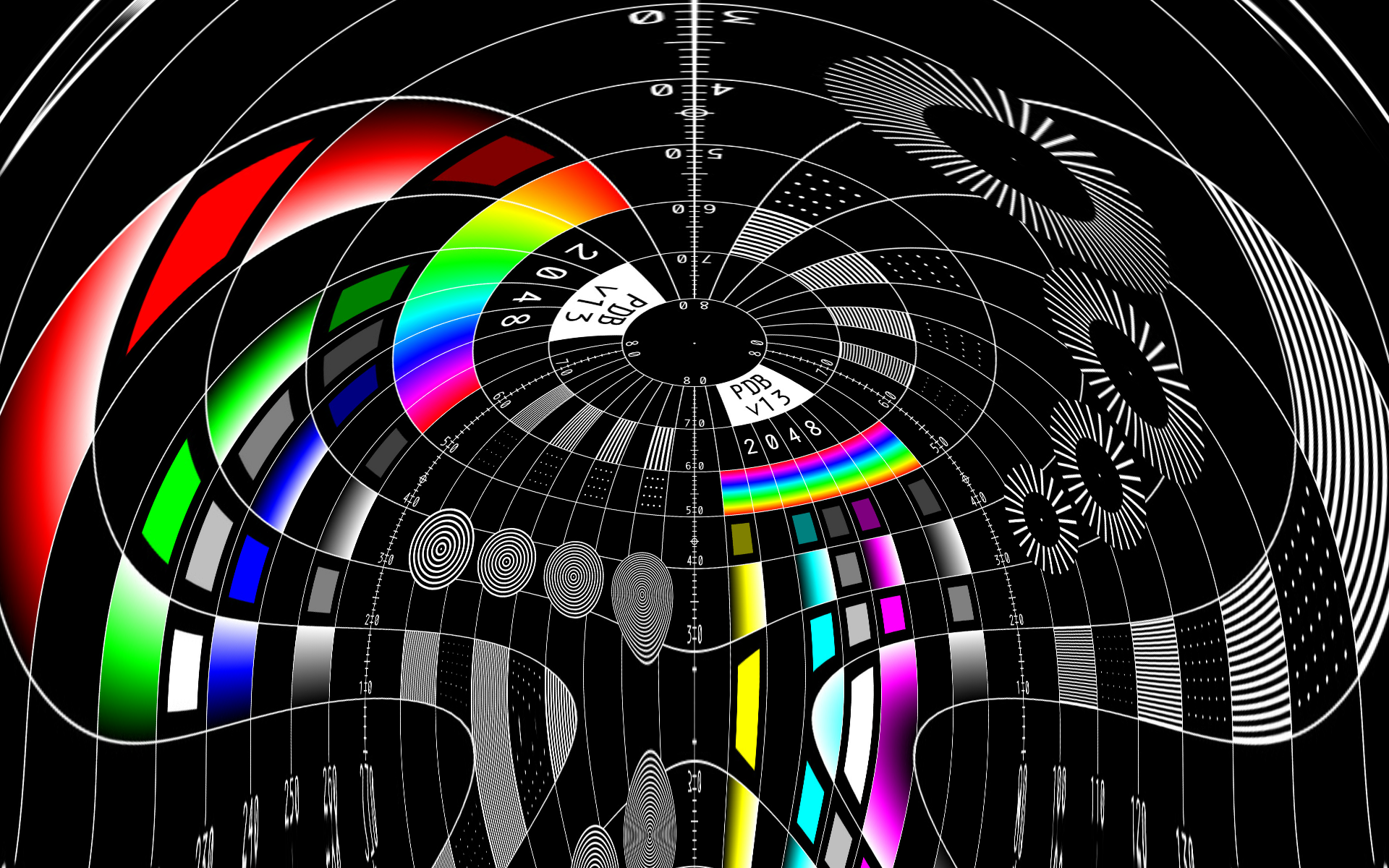
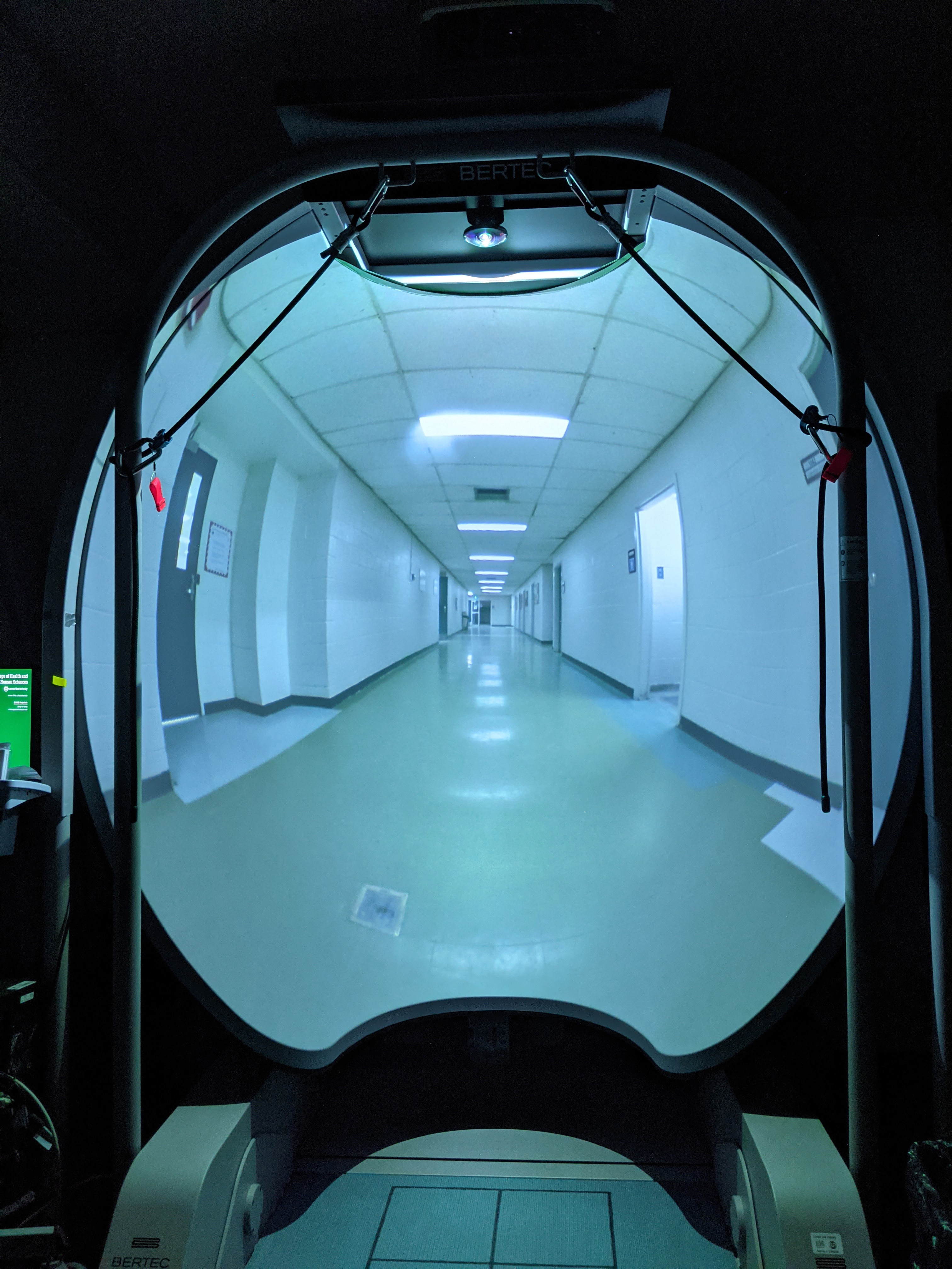
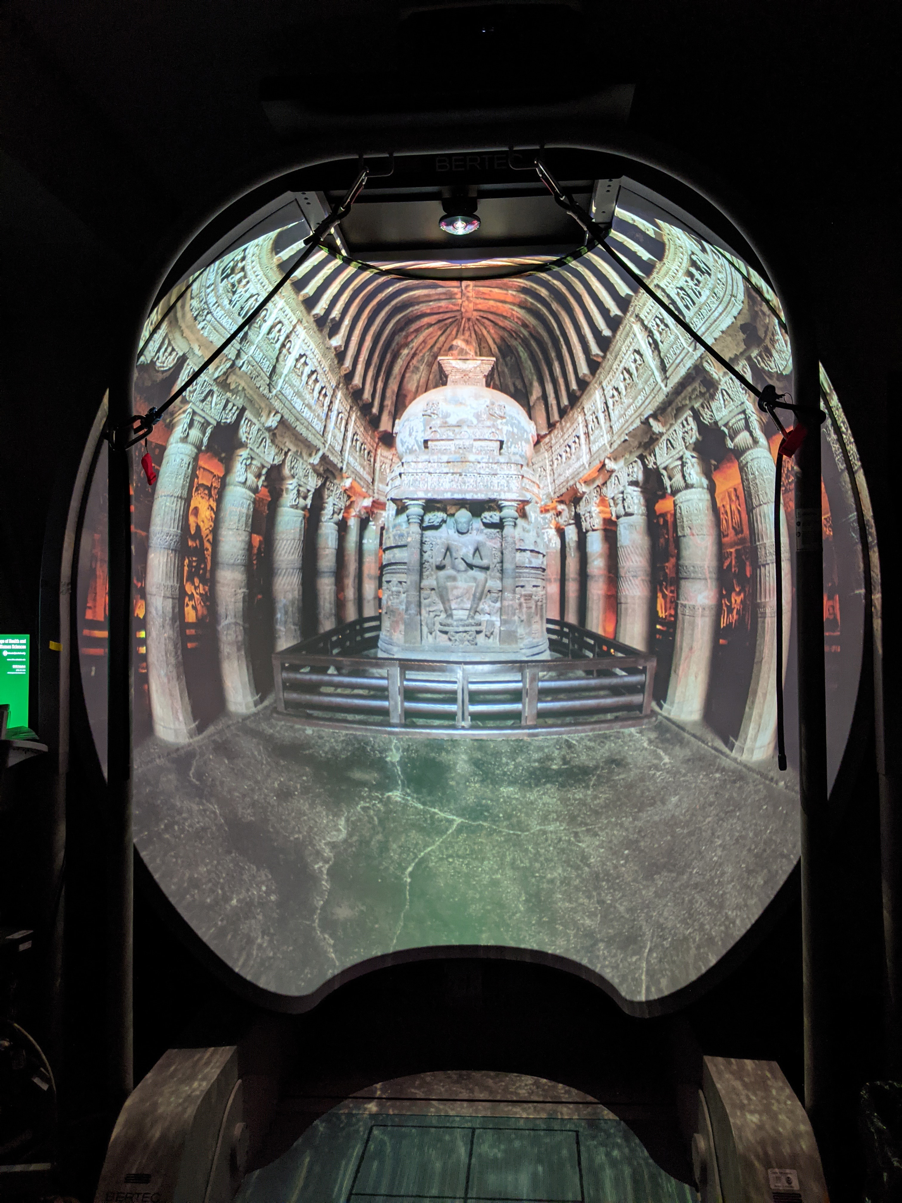
The result in the dome, noting that the camera is not at the same location as the intended viewer but much further back, as such these images will look a little distorted especially towards the high curvature edges. Note also that much of the extreme parts of the image above lie outside the dome, this would normally be masked. 
|