Full dome projection using three projectors
Written by Paul Bourke
July 2005
|
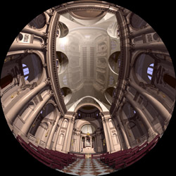
Input fisheye image
The input to a full dome projection is normally a fisheye image, more precisely
an equal angle fisheye (equally spaced lines of latitude). Such fisheye images
may make up the frames of a full dome movie or be created in realtime using OpenGL.
|
|
|
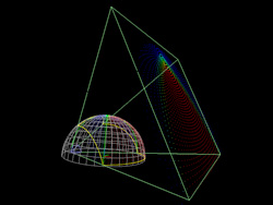
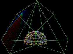
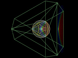
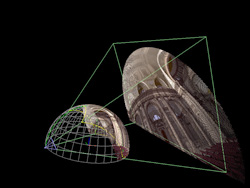
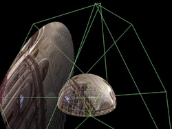
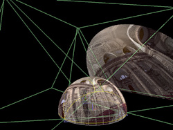
Projector frustums
Green lines show the projector frustum, in this case a 0.8:1 throw projector
with a 4:3 aspect ratio. The yellow curve on the dome is the intersection of the
frustum with the dome, ie: the part of the dome illuminated by a projector.
In order for the dome to be completely covered the
projectors are mounted slightly below and back from the rim of the dome, of course
this longer throw can also be achieved with a mirror.
1 projector and frustum plane
|
2 projectors, showing overlap
|
3 projectors, top view
|
|
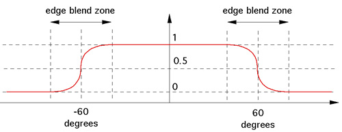
Edge blended images for each projector
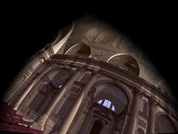
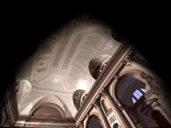
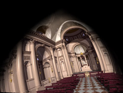
The following three images are what is projected by each of the three projectors
in order to achieve a total seamless coverage of the dome surface. Each projector
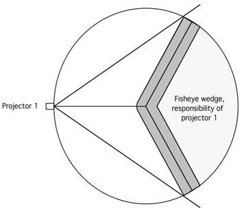
is responsible for a 120 degree wedge of the dome surface, the edge blending is
applied across the edges of each wedge. While not obvious in these images, the
zone at the top of the dome has an edge blend across three images rather than
just two.
|
|
|
Projector 1
|
Projector 2
|
Projector 3
|
OpenGL texture meshes for each projector
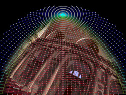
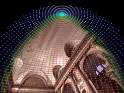
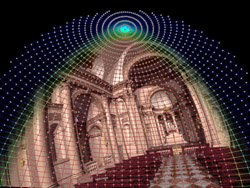
The warping and edge blending is achieved in real time by using a textured mesh
in OpenGL. Similarly an off-line warping can be applied to movie style content that
creates a higher quality antialiased result, at the sacrifice of being able to
readily change the projector alignment and edge blending.
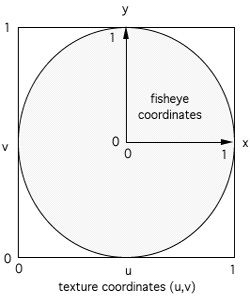
Each node of the mesh is described by a position (x,y), texture
coordinate (u,v), and gamma corrected edge blend factors (r,g,b). The red zones
is where edge blending factors are unity, the blue regions where they are zero, and
the blending between those.
The fisheye image is applied as a texture to this mesh.
|
|
|
Projector 1
|
Projector 2
|
Projector 3
|
Result on dome
While not particularly clear, the following shows the fisheye projected onto the
dome. A correct undistorted view can only be achieved by actually being in the
dome and standing in the center.
Projector 1
|
Projector 1 and 2
|
All projectors
|
Deriving warping mesh
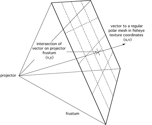
There are at least two ways of creating the OpenGL warping mesh, one is
to trace rays through a regular grid in the projection plane and determine where
the ray strikes the dome and hence the texture coordinates in the fisheye texture.
Another method, and the one used here, is to form a regular polar grid in fisheye
space and determine the intersection on the projection plane of the vector to the
corresponding position on the dome. Either of these would work but the later
is more convenient when deriving the edge blending. The polar nature of the warping
mesh can be seen in the images above that show the mesh.
|


