S p h e m i rDome projection on a budget, also known as MirrorDomeWritten by Paul BourkeOctober 2003, updated December 2004
The following illustrates a method of projecting onto a dome without the need for a full fisheye lens which are both rare and, those that do exist, only fit to a narrow range of projectors. The approach here uses a mirror to reflect images from the projector onto most of the dome surface. 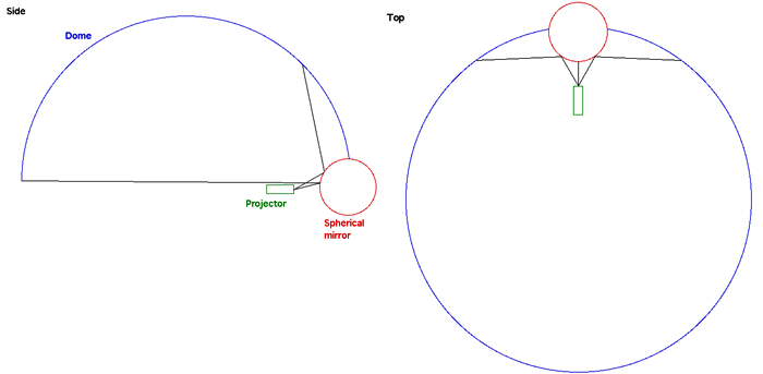
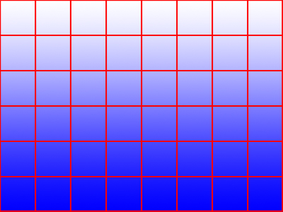
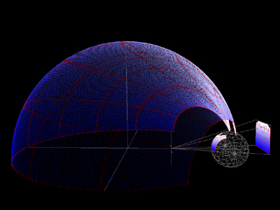
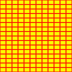
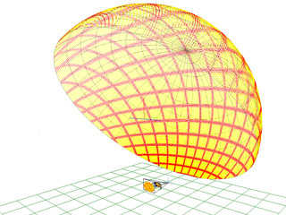
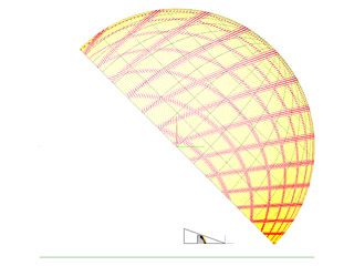
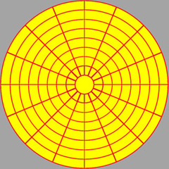
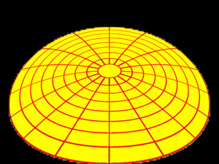
Projecting a 4:3 image of a grid (below left) is shown below on the right. This is an optical simulation (dimensionally correct) given a particular dome and mirror configuration, and using a real projector specification.
Geometric correction
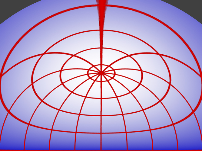
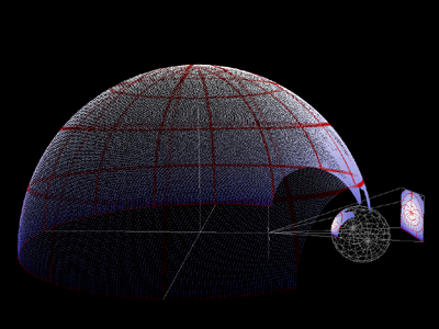
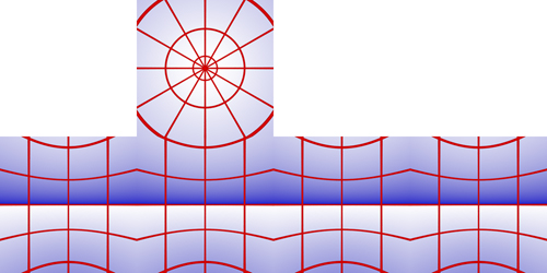
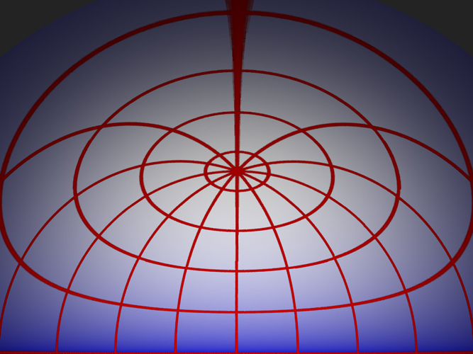
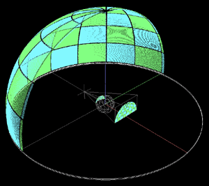
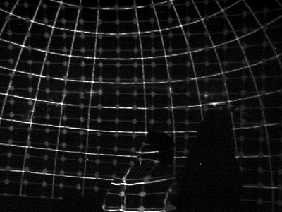
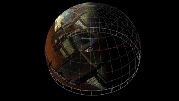
To create an undistorted image on a dome using this mirrored system, the projected image needs to be pre-distorted. The distortion required can be derived from the geometry, an example of this is shown below on the left and the projection onto the dome on the right. As can be seen the image on the dome looks correct, the red are lines of longitude and latitude.
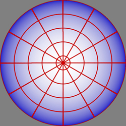
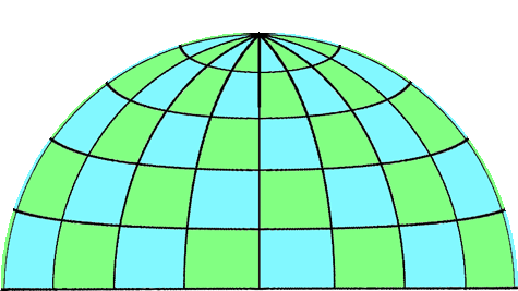
As with most dome image creation, one either renders a cubic environment (perspective projection to 5 sides of a cube) and then resamples onto an angular fisheye image, or if the rendering software supports it the fisheye image is rendered directly. The model used to create the image above is simply a sphere made up from a grid of lines of longitude (every 30 degrees) and latitude (every 20 degrees). The cubic texture and spherical map are shown below, the distorted image above can be derived from either of these two representations. This is the obvious candidate for a test pattern because one knows the pole should be in the top/center of the dome and the lines of longitude and latitude should be straight, assuming the observer is located in the center of the hemisphere.
Brightness correction
There is a variation in the light path to different parts of the dome, this would normally result in an uneven brightness across the dome (brighter the shorter the light path). This is straightforward to correct for, see the brightness function below on the left and corrected image on the right.
Notes
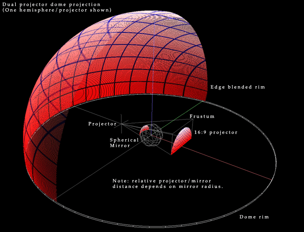
There are three ways of deriving the transformations required and shown on this page. One can derive the mapping analytically, while this may be possible for idealised arrangements, for other more real world situations it can be cumbersome. A second way is to develop an application that allows the mappings to be created interactively, by moving vertices and (u,v) coordinates of a mapping mesh until the correct mapping is achieved. The third way and the one used here is to simulate the projection environment. Trace rays from the projector through each pixel in the image, reflect the ray off the mirror and onto the dome, once the position on the dome is known the mapping for the pixel in question can be calculated. Full dome and other configurationsIn the examples above the full dome is not illuminated, this is intentional and is similar to most fisheye projection solutions which project onto 3/4 of the dome surface. A dual projector arrangement with a single edge blend across the center is the simplest way to get complete dome coverage. There are many alternative arrangements, the following is one possible configuration for full dome using a central mirror. Similar arrangements for full domes can be achieved with the mirrors near the rims of the dome as before.
Advantages over fisheye projection
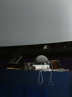
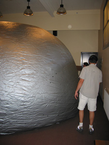
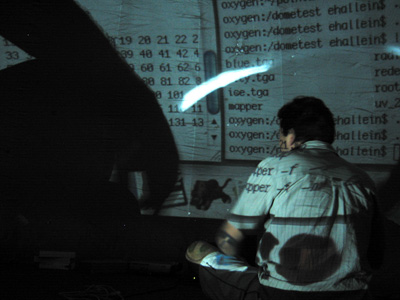
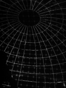
Example 1 - Planetarium dome The first real tests of these ideas were conducted at the Wollongong (Australia) Science Centre using a very basic rig as shown below (Laptop, data projector, and 1/4 sphere security/safety mirror). Software was developed that computes the warping texture map from a simulation of the projector/mirror/dome arrangement. Software to view stills and animations plays fisheye movies and warps them in real time.
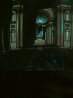
Please note that while the two pictures in the dome (top right) appear to be distorted (eg: curved columns) that is because the images were taken down the corridor leading into the planetarium. From within the planetarium the images appear undistorted. Example 2 - Starlab dome
Example 4 - Tilted domes
The following is a demonstration of how the full dome projection might work in a 45 degree tilted dome. Note that the warping is dependent on the projector being used, the simulations shown here are based upon a 4:3 SXGA+ resolution projector, namely the DELL 5100MP. 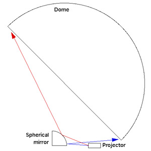
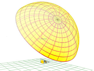
If you were to place a spherical mirror and projector as shown (not drawn to scale) and project a regular grid (left) then the result on the dome would be as shown on the center and right. Click to enlarge images. These are derived by my ray casting simulation software that also calculates the warping specification.
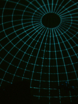
Consider a polar grid (left) and the warped polar grid below (center), when projected into the dome the correctly mapped image is achieved, namely lines of latitude and longitude.
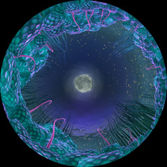
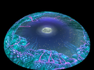
A real example, a single frame from "Moonlight" by Andrew Quinn. To create a warped movie one simply applies the warping to each frame of the movie.
Example 5: Full dome projection using two projectors and two spherical mirrors
The following illustrates how to achieve full dome projection using two projectors and two quarter hemisphere mirrors. While the mirrors can be located on the rim of the dome, here they are located in the center so the projected images are not blocked by a star projector located in the center. It should be noted that 3 and 4 projector/mirror configurations are equally possible with the corresponding improvements in resolution. The two projector configuration shown here has the benefit of simplicity from the point of view of only requiring a single computer with a dual display graphics card for movie playback and interactive applications.
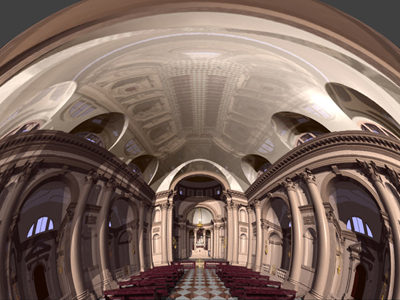
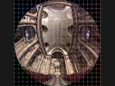
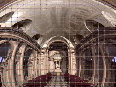
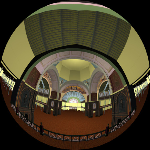
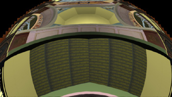
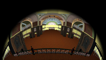
The input imagery for a dome system is usually a fisheye image, an example is shown below (Royal Exhibition Building model, Melbourne, Australia) and it will be used for the subsequent examples. The approach proposed here warps the image (movie frames) in real-time, relatively straightforward with todays graphics cards. The only trick is determining the warping function which is implemented using an OpenGL mesh with special texture coordinates, the fisheye images are applied as textures to this mesh.
The following two images are created by applying the fisheye image above to a mesh with the appropriate texture coordinates, one for each projector. The texture coordinates for the mesh are derived by accurately modelling the dome, mirrors, and projectors. Rays are forward traced from the projectors, through the mesh nodes, off the mirrors and onto the dome. Once the position of a mesh node on the dome is known, the texture coordinates for the mesh node can be calculated.
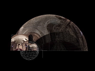
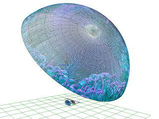
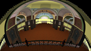
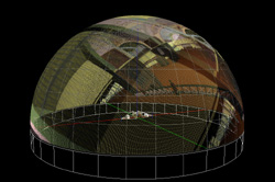
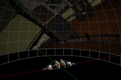
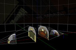
The following are screen shots from the software that models the geometry of the environment and traces rays from the projector onto the dome. The zoomed in image on the right shows the projector frustum, the image projected onto the mirror surfaces, and the result on the dome. In the image on the bottom right the virtual camera is close to the center of the dome so there is no distortion of the image on the dome, eg: the handrail is straight.
A single edge blend is required across the axis perpendicular to the projector axis. The two projected images are created so they overlap and a smooth intensity ramp (gamma corrected) is applied across the overlap region so that the perceived brightness add together correctly to give a seamless effect.
Notes
| |||||||||||||||||||||||||||||||||||||||||||||
