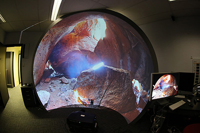
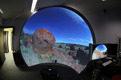
Image warping for offaxis fisheye lens/projectorsWritten by Paul BourkeSept 2013
In what follows, the means by which one calculates the image warping required to project into a dome with a projector and fisheye lens where they are not located on the axis of the dome. The approach taken is in line with existing methods of hemispherical projection using a spherical mirror, that is, the frames of a fisheye movie are warped by being applied to a regular mesh consisting of vertices and texture coordinates. How to define the vertex coordinates and texture coordinates will be outlined here.
If the fisheye lens is an ideal fisheye and located at the correct position along the axis of the dome then potentially no image warping is required (although see later where one may need to correct for non-ideal fisheye lenses). For all other cases it is required in order to achieve a correct undistorted image in the dome. The following outlines the steps for determining how to warp a fisheye in such a way such that the result looks correct on the dome. This requires a knowledge of:
The first step is determining the vector from the fisheye corresponding to any point in the image plane. This will be calculated for each vertex of the warping texture mesh, the eventual goal being to determine the corresponding texture coordinate. Note that normalised screen coordinate will be used here as is standard with real-time APIs such as OpenGL which is the usual way real-time warping will be implemented. If nx and ny are the number of vertices in the warping mesh, horizontally and vertically, then the point p in normalised screen coordinates would be determines something like this, where "a" is the aspect ratio defines as the frame width divided by the frame height.
   for (i=0;i<nx;i++) {
      for (j=0;j<ny;j++) {
         p.x = 2 * a * (i / (nx-1) - 0.5);
         p.y = 2 * (j / (ny-1) - 0.5);
          :
          :
      }
   }
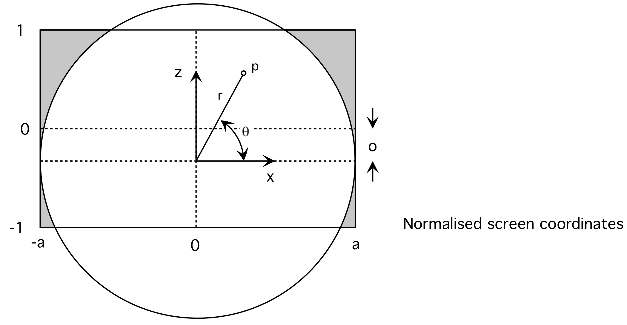
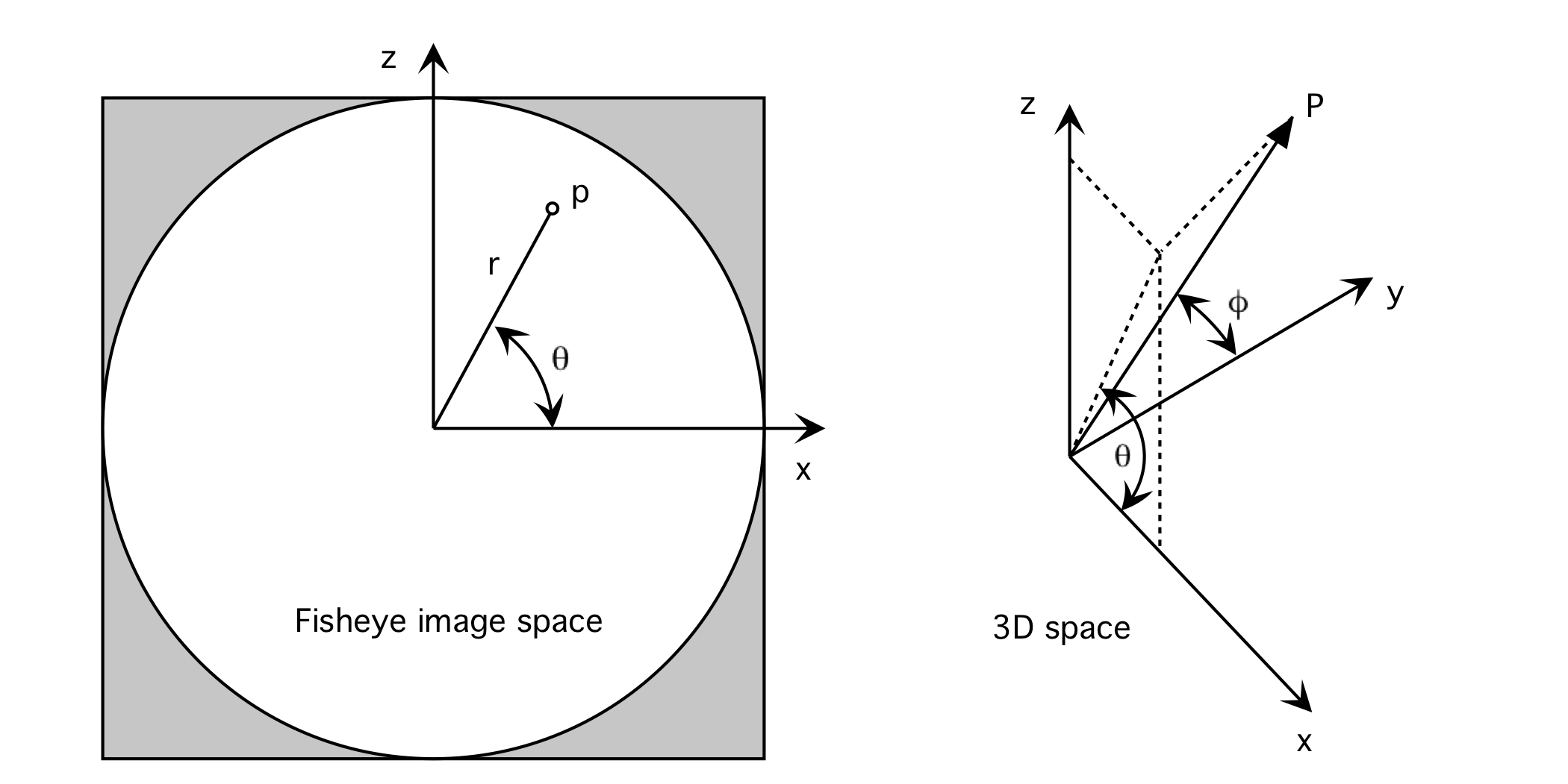
An ideal (mathematical) fisheye projection is characterised by a linear relationship between the radius "r" of a point on the fisheye image (2D) to the angle phi of the vector (3D) it represents from the lens. While a fisheye is defined for any field of view, for a 180 degree fisheye the relationship is:
If p is a pixel in fisheye image space then it corresponds to vector P in 3D space as shown in diagram 2. (Assumes 180 degree fisheye and lens pointing down the y axis). This 3D vector may be determined as follows
          :
          :
         // Ray vector
         p.x = p.x / a;
         p.y = 0;
         p.z = (p.y - o) / a;

         // Determine unit vector into scene
         r = sqrt(p.z * p.z + p.x * p.x);
         phi = 0.5 * r * PI;
         theta = atan2(p.z,p.x);
         P.x = sin(phi) * cos(theta);
         P.y = cos(phi);
         P.z = sin(phi) * sin(theta);
          :
          :
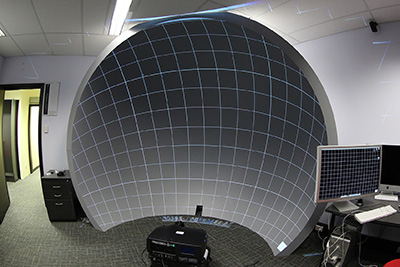
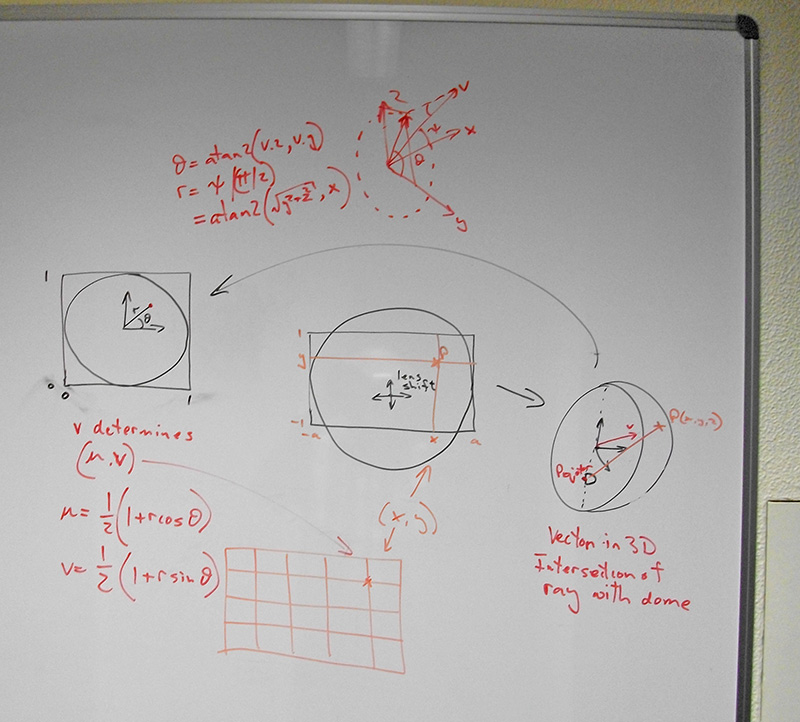
Using the vector from the fisheye lens the next step is to relate that to the physical geometry/optics in the dome. Where this vector intersects the dome is where the point in the image plane will appear. One can form a ray given the projectors physical position and orientation, the domes position, size and orientation, and the vector P above. See diagram 3. Computing the intersection of this line with the dome can be achieved by using the code found here. 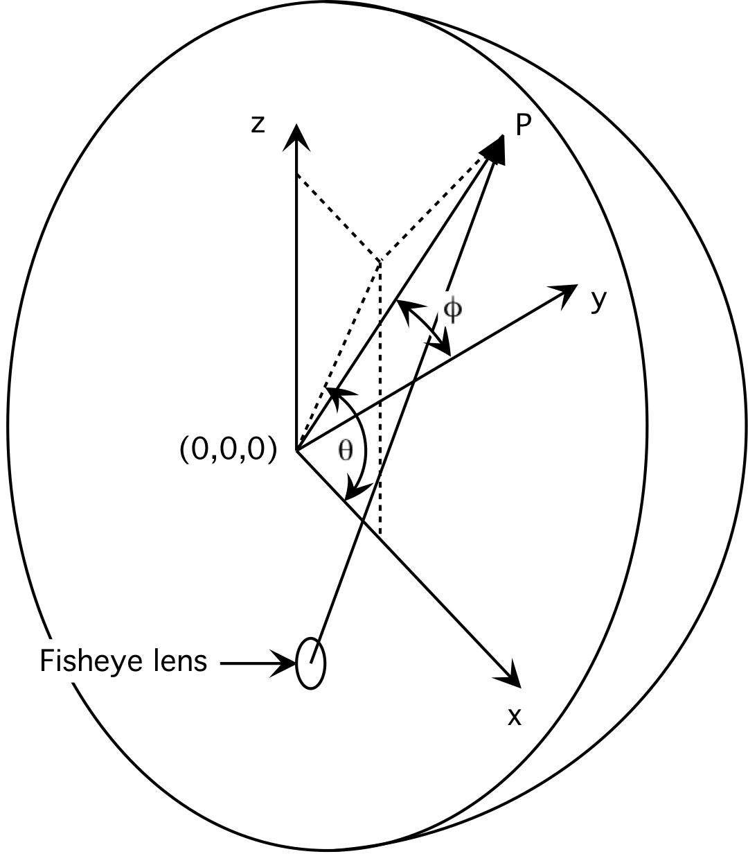
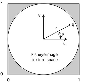
Given this position on the dome, we know how the fisheye should map to that. If q is the intersection on the dome then the texture coordinate (u,v) corresponding to this position in the projected image is
          :
          :
         phi = atan2(sqrt(q.x*q.x+q.z*q.z),q.y);
         r = 2 * phi / PI;
         theta = atan2(q.z,q.x);
         u = 0.5 * (1 + r * cos(theta));
         v = 0.5 * (1 + r * sin(theta));
          :
          :
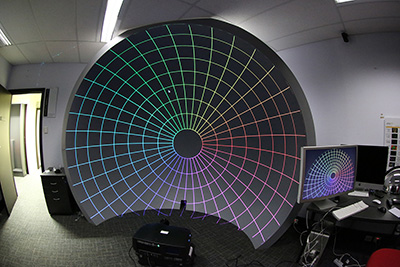
The image on the right below shows the standard polar grid alignment pattern. The warping can be verified by ensuring the pole is at the right place, radial lines (longitude) are straight, and lines of latitude are perfect circles.
An ideal (mathematical) fisheye projection is characterised by a linear relationship between the radius "r" of a point on the fisheye image (2D) to the angle phi of the vector (3D) it represents from the lens. Most lens do not have such a perfect linear relationship, those that do are sometimes referred to as f-theta lenses. The non-linearity is usually most obvious towards the rim of the lens where there is generally a compression. There are a number of ways of correcting for this, for the lens in question here the manufacturer provides the radial correction required, this is in the form of a fit to a polynomial.
|
