Define Marker Glyph
Purpose
The Define Marker Glyph function adds a new glyph (a collection of geometric primitives) or redefines an existing glyph to the table of marker glyphs.
Syntax
| Opcode format | Opcode | Operand Format | Comments |
| Extended ASCII | (Glyph | <ws><IIndex><ws><IX>,<IY><ws><Iunit><ws>(<Rdefinition1>)) | Assigns a sequence of opcodes to a marker glyph index |
| Extended Binary | 0x0003 | <USindex><LX><LY><ULUnit><Rdefinition2>} | Assigns a sequence of opcodes to a marker glyph index. |
Index The index into the marker glyph table of the glyph being added or replaced; legal values range from 0 to 65,535
X,Y The logical coordinate origin of the glyph being defined
Unit A logical coordinate distance indicating the unit size of the glyph
Definition1 A nested series of readable ASCII opcodes to be stored (rather than rendered) at the position indicated by the index argument in the marker glyph table
Definition2 A nested series of opcodes to be stored (rather than rendered) at the position indicated by the index argument in the marker glyph table
Details
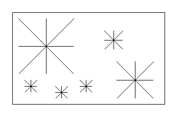
The Define Marker Glyph opcode allows a DWF writing application to define a pattern of geometric primitives, which may later be reused multiple times with the Draw Polymarker opcode. Inside the Define Marker Glyph operand is a nested series of opcodes that are stored (rather than rendered) that represent the marker glyph being defined. For example, suppose you wanted to represent the illustration in figure 1 as a .dwf file.

Figure 1. Glif definition
You could define a new glyph for the "star" shape and later use the Draw Polymarker, the Set Marker Glyph, and the Set Marker Size opcodes to render the six star instances more efficiently.
When recording the geometric primitives for a glyph, an arbitrary set of logical coordinates is used. Later when a glyph is drawn with Draw Polymarker, these arbitrary coordinates are related to specific coordinates by the Origin and Unit arguments. In this example, a star shape is "recorded" at index 12 in the glyph table, centered about the arbitrary vertex (300,300), and given a unit size of 100 logical units:
(Glyph 12 300,300 100 (
L 250,300 350,300 (Comment Horizontal line)
L 300,250 300,350 (Comment Vertical line)
L 250,250 350,350 (Comment right angled line)
L 350,250 250,350 (Comment left angled line)
))
When drawn with the Draw Polymarker opcode, the glyph's origin is translated to the marker's insertion point, and the glyph is scaled such that its unit vector has a length equal to the current marker size attribute (in logical space).
The definition of a glyph may include any sequence of geometric primitives (Draw opcodes) and/or attributes (Set opcodes). For many glyphs, as in the star example, no attributes are stored only geometric primitives so that the attributes active at the time Draw Polymarker is executed will be used. In this example, you can draw a red and a blue star with the following:
G 12 (Comment Select the previously defined "Star" glyph.)
S 30 (Comment We'll draw stars that are 30 logical units high,
which is 15 units above and below the "origin".)
(Color 255,0,0,255) (Comment Get ready to draw in red.)
M 1 500,400 (Comment Draw one red star centered at 500,400.)
(Color 0,0,255,255) (Comment Get ready to draw in blue.)
M 1 600,700 (Comment Draw one blue star centered at 600,700.)
At other times you may want marker glyphs to be defined with both geometric primitives and attributes. For example, to define a multicolored plus sign glyph, you can specify
(Glyph 17 30,30 10 (
(Color 255,0,0,255) (Comment override current color to red.)
L 25,30 35,30 (Comment Red Horizontal line.)
(Color 0,0,255,255) (Comment Select blue.)
L 30,25 30,35 (Comment Blue Vertical line.)
))
Immediately before such a recorded glyph is played back with the Draw Polymarker operation, a copy of the current attribute state is saved. The state is restored after each marker in the polymarker list completes DWF maintains an attribute scope. In this example, the diagonal line is drawn in green rather than the blue from the plus sign glyph:
G 17 (Comment Select the previously defined "Plus" sign glyph.)
(Color 0,255,0,255) (Comment Get ready to draw in green.)
M 1 500,400 (Comment Draw a red and blue plus-sign.)
L 250,250 350,350 (Comment A *green* diagonal line.)
Notes
Any glyph stored in the glyph table may be replaced by reissuing the Define Marker Glyph opcode with the same index value.
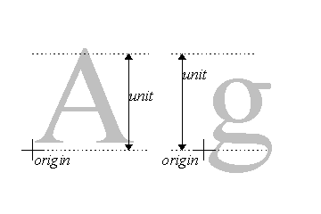
For many glyphs, as in the previous star example, origin is centered inside the glyph's bounding box and unit is the width or height of the bounding box. However, for some glyphs this will not be the desired arrangement. For example, the characters of a font could be encoded as a set of glyphs (one for each character) containing polygon opcodes. In this case, unit would be set to the height of the of the tallest character in the font, rather than the height of each character being defined, and origin would be positioned at each character's insertion point, as shown in figure 2.

Figure 2. Font characters encoded as glyphs
In order to achieve the greatest precision of the marker glyph being defined, the geometric primitives provided should use a large range of logical coordinate space and as a result, a large Unit value.
By convention, if the extended ASCII version of the Define Marker Glyph opcode, "(Glyph", is used, then all opcodes contained in Definition should also be ASCII opcodes (either single-byte or extended) so that DWF reading applications may safely skip the Define Marker Glyph operation. When Definition contains binary data, the extended binary version of Define Marker Glyph (opcode 0X0003 in hex) should be used.
Default
By default the Glyph's listed in table 1 are defined initially by the DWF reading application.
| 0 | Single Pixel |
| 1 | Plus |
| 2 | X |
| 3 | Star |
| 4 | Hollow Circle |
| 5 | Filled Circle |
Note: The exact definitions of these glyphs is implementation specific.
Implementation in WHIP! Versions
| Toolkit Function |
TBD |
Partial |
Full |
Revised in |
| Define Marker Glyph | - | - | - | - |
See Also