Virtual Containment Vessel
Now known as VROOM - Virtual ROOM
or once known as the Virtual Reality Observatory of Melbourne
Installed at the Museum of Victoria in Melbourne and MOTAT in Auckland.
Presentation, November 2002
Draft 2, January 2002
Draft 1, October 2001
|
|
|
Background
The idea of the Virtual ROOM (originally called the Virtual Containment Vessel) was initially
proposed by David Barnes in 2001. The basic idea was modified and finally designed
by the author in the following year, much of the original projection details and
content was also developed by the author in conjunction with a student animator Evan Hallein.
This culminated in a consortium of content partners and in an installation at the Melbourne Museum
in 2003.
Subsequent installations occurred as a "semiportable" version that did a partial
world tour and ended up at MOTAT in Auckland in 2005.
The rest of this document is historical in some sense, it is the
original web page describing the concept and likely design layouts.
Introduction
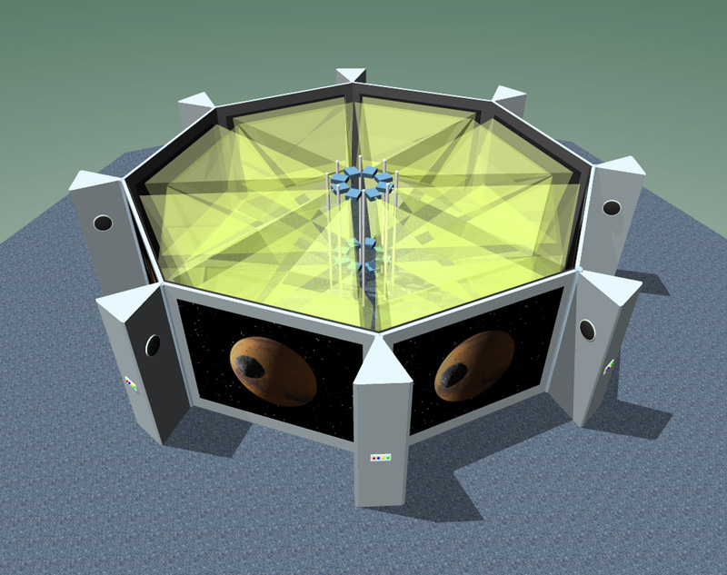
The following describes a unique system for the presentation of virtual objects
and contained virtual environments. The installation consists of N
walls (N = 8 will be used in this
discussion) each of which contains a window displaying stereoscopic 3D
images. The walls are arranged in a circular fashion (octagon)
to form a vessel that is supposed
to be containing or generating the objects that make up the virtual
environment, see figure 1. The audience walks around on the outside of the structure
wearing passive polaroid
glasses (for the stereoscopic effect) and they perceive virtual objects
that appear to be within the confines of the containment vessel.
Design Concept
The key concept is to create the illusion that the virtual objects and environment
is being created by a physical device, the VCV.
The attempt is to blur the line between what is
physical (the exterior of the virtual room) and the virtual (what is being projected
in stereo3D such that it appears on the interior of the virtual room).
One of the motivating ideas arose from the realisation that CAVE's, while particularly effective
at giving one a sense of being within a virtual environment, are not always
appropriate for scientific visualisation that often deals with contained (finite)
bounded systems. While a CAVE is appropriate for exploring a proposed building say, it is
less useful when studying a molecular simulation where there may be little gained
from being inside the molecule. Another motivation
was that single person immersive environments
are less suited to museum and other general public exhibits because they don't provide
sufficient throughput.
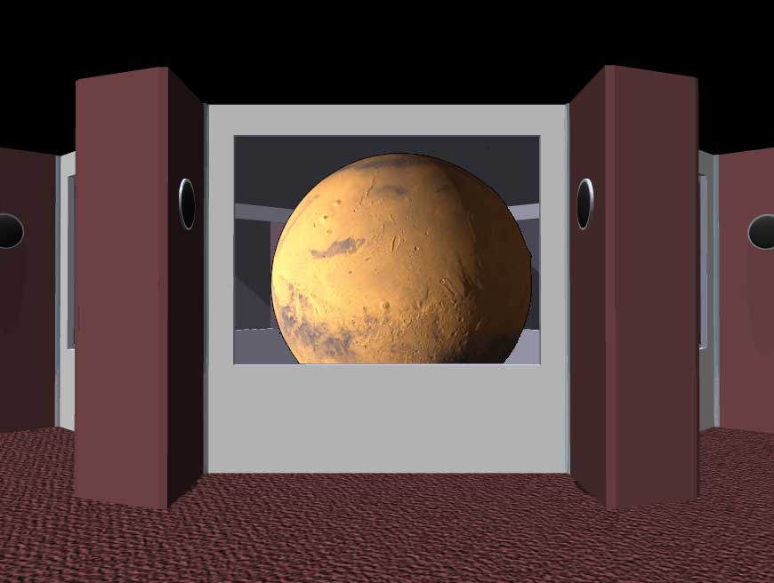
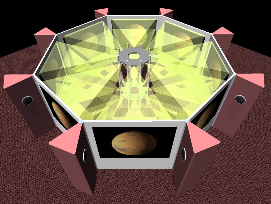
One important addition is that if the viewer sees the interior structure of the
VROOM (virtually that is) then that will enforce the sense of the virtual
objects residing within some physical structure, see figure 2. Of course the interior
need not appear the same for different pieces of content. The stereoscopic depth
cues need to be precisely formed so the virtual interior view matches the physical
external structure of the VROOM.
For example, astronomical content might render the interior with a futuristic
spaceship style while for content based upon artificial life the interior of the
virtual room might take the appearance of a cage or laboratory.
The details of how the virtual room is supposed to be creating the virtual objects
might be explained differently as well, perhaps as part of a story being
told through the audio system. For some content the virtual room might be explained
as a holographic projector or perhaps a particle transporter, while for
other content the virtual room might be something more down to earth such as a cave
or the interior of some ancient architecture.
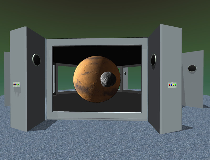
Interactivity
Another consequence (that should be encouraged) is that when some interesting
part of the virtual environment is closer to, or clearer from,
a particular window then any member of the audience can walk around
the virtual room to get a better view. For example in
figure 3 while Mars is central, one of the moons might be closer to another
window. To get a better view of a particular moon or even the daylight side
of Mars, the audience would go to the relevant window.
Imagine a virtual model of a city, in order to look along a particular
street or to look more closely at a particular building one would move around
to the best or closest window.
There are very elegant effects that might be achieved using the stereo
audio channels at each window. If a dinosaur made a noise near one window
it would be loudest there and less loud (more distant) at other windows.
The audio could be another cue that would encourage the audience to walk
around and explore where the sound came from.
A particular piece of content may or may not require user interaction
but if there is then all windows would normally reflect the same state.
In all cases the illusion of the virtual room is best maintained by all windows
showing the correct views of the same environment so things are consistent
when the observer moves to a different view.
For example, if the virtual room contained an evolving galaxy then it might be
interesting enough to watch as just a time varying system with a audio track.
On the other hand, for other simulations the audience might be able to vary
parameters using an input device provided at each window. With a 3D input
device, like a wand, members of the audience might be able to project a
pointer into the environment.
Imagine an exploratory environment (eg: deep sea) where viewers
point with a 3D wand which becomes a beam of light into the virtual world.
Head tracking would enhance the illusion because then the viewer
could look through the windows askew and they would would be presented
the correct stereo pairs as if they were looking through a window on an
angle. Like most head tracking systems this introduces extra
complexity, precludes precomputed content, and restricts each window to
one viewer at a time.
|
|
Figure 1
Figure 2
Figure 3
Figure 4
Figure 5. The images above were there very first concept drawings.
In the end the throw of commodity projectors was not wide enough
to support the projectors being located in the center. This would have
allowed the wedges to be independent and the virtual room could have been quickly
rearranged into different geometries. In the final configuration the
projector for a particular screen is located underneath the opposite
screen.
| |
Paul Bourke, 2001
|
Paul Bourke, 2002
|
Evan Hallein, 2003
|
While there is nothing magic about 8 screens, there are some constraints. For example
4 screens wouldn't be enough to give a sense of continuity. Many more would have the
undesirable effect of an observer seeing more than one at a time (illusion doesn't work).
Note that in the original plans baffles were proposed between the screens, it was also
imagined that these would house speakers and perhaps other interactive devices. This
use of the baffles didn't make it into the final design although thin walls did separate
the screens.
VROOM panoramas
If all eight images are placed side by side the result is what was known as
a "VROOM panorama", of course there is one panorama for each eye. Note that a frame
for the virtual room requires 16 images. The projectors were XGA resolution (1024x768) and
the movies ran at 25 frames per second. So one minute of content requires
25 x 60 x 8 x 2 images = 24000 frames! For optimal quality the movies originated as
uncompressed frames, so each minute consists of 24000 x 1024 x 768 x 3 bytes
which is over 52 GB.
Virtual Garden [Click to enlarge]

Spline tree generator by Andrew Clinton
Virtual Asteroid Display [Click to enlarge]

Collection of asteroids, animation by Paul Bourke.
Jerash [Click to enlarge]

Model courtesy of Chris Little, Stephanie Phan, Andrew Hutson, Frank Sears (Melbourne University)
Egyptian tomb [Click to enlarge]

Created by Evan Hallein.
Pyramid [Click to enlarge]

Created by Evan Hallein.
Jellyfish [Click to enlarge]

Created by Evan Hallein, Natasha Roberg, Alex Harkness.
This is the very first animation sequence created for VROOM (using 3DStudioMax).
City plan [Click to enlarge]

City generator by Chris Colefax.
It was proposed in the original design that the exterior of the VROOM structure
could change by being able to hang/clip decoration to a basic shell. So a particular piece
of content could have a related appearance in reality to the virtual content. Fort example,
the walls and pillars
in the pyramid example above would extend out into reality greatly enhancing the illusion.
Models
In order to get the stereoscopic parameters correct, the recommended approach to content
creation is to model the VROOM structure in world coordinates and place the virtual camera
pairs (one pair for each screen) in the sweet spot located 2m in front of each screen. Precise
off-axis frustums are set up for each (parallel) camera or the extended render and trim
method can be used with symmetric frustums. Such templates were created for 3DStudioMax, Lightwave,
and Maya .... an example for POVRay is given here:
PovRay template.
Installation (December 2003)
In the final installation at the Melbourne Museum, each screen was 2m wide and used
the Stewart Filmscreen 200 (polarisation preserving) screen surface attached to the
back of a rigid plexiglass substrate. There are in total 16 projectors, at the time
the NEC LT265 was chosen because of the 3DReform feature that allowed rapid pixel perfect
alignment of the projector pairs.
The 3DReform feature has been dropped from the NEC DLP line of projectors, for this and
other quality reasons it is now suggested that the image alignment be done in software
by projecting all content onto a texture mesh in OpenGL, a standard technique for geometry
correction in curved surface projection environments. The alignment procedure needs to
be quick and accurate since there are 8 pairs to align and alignment would typically need
to be performed "not infrequently" for an ongoing good quality result (projectors and racks
naturally shift slightly due to vibration and heat stress).
|