This section will illustrate how to create correct stereo pairs using rendering software that supports standard perspective projections. PovRay has been chosen because it is often used as a means of visualising datasets mainly due to its very flexible scene geometry and macro language. PovRay is also available on almost all platforms and the UNIX version can be readily scripted to render scenes automatically, a big advantage for camera animation and time varying datasets. This is not intended to be a tutorial on how to run PovRay, the discussion will be limited to creating a correct stereoscopic camera model. The principles here should be readily transferable to other rendering packages, and indeed the author has used the same technique for packages such as 3DStudioMax, Lightwave, Tachyon, and others. PovRay at the time of writing (Version 3.5) does not have explicit stereoscopic support and it does not support offaxis (asymmetric) frustums. The approach then is to render a wider symmetric frustum that contains the offaxis frustum we require and trim off extra image columns that aren't required. This is illustrated below, the symmetric frustum as viewed from the top is shown on the left (top row). The desired asymmetric frustums are also shown on the top row for each eye. These asymmetric frustums can be extended to symmetric ones, these can be rendered by PovRay and the extra unwanted pixels trimmed from the resulting images.  There are many ways to specify a camera in PovRay, in this discussion the camera pair for stereoscopic rendering will be based upon the following PovRay camera definition. This is a very general description and places the camera in world coordinates.
#declare WIDTH  = 1024;
#declare HEIGHT = 768;
#declare RTOD = 57.2957795;
#declare DTOR = 0.0174532925;
#declare APERTURE = 60 * DTOR;
#declare VP = <10,2,0>; /* Camera position       */
#declare VU = <0,0,1>;  /* Camera up vector      */
#declare VD = <-1,0,0>; /* Camera view direction */
#declare VR = vnormalize(vcross(VU,VD)); /* Right vector */
camera {
   perspective
   location VP
   up y
   right WIDTH * x / HEIGHT
   angle APERTURE * RTOD
   sky VU
   look_at VP + VD
}
Graphically this can be illustrated as follows. Note that this is a very general camera definition and gets away from assumptions often made by PovRay modellers that the up vector is along the y axis. Note also that PovRay uses a left hand coordinate system, if a model is being converted from a right hand coordinate system then the line specifying the right vector should be changed to right -WIDTH * x / HEIGHT".  In order to specify a left and right eye symmetric frustum a new image width and camera aperture need to be calculated. The extra image width is given as follows where e is the eye separation in world coordinates, fo is the focal length (distance of zero parallax), a is the desired camera aperture (horizontal), and w is the final image width. Note that some packages specify the camera aperture as the vertical aperture. 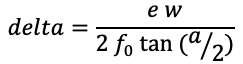
The camera aperture is modified as follows. 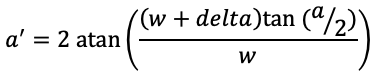
The modified camera definition is given below. Note that the modified image width (WIDTH+DELTA) must also be used in the command line or ini file definition of the image width. The scene is rendered twice, once with EYE set to 1 (for the right eye) and once with it set to -1 (for the left eye).
#declare WIDTH  = 1024;
#declare HEIGHT = 768;
#declare RTOD = 57.2957795;
#declare DTOR = 0.0174532925;
#declare APERTURE = 60 * DTOR;
#declare VP = <10,2,0>; /* Camera position       */
#declare VU = <0,0,1>;  /* Camera up vector      */
#declare VD = <-1,0,0>; /* Camera view direction */
#declare VR = vnormalize(vcross(VU,VD)); /* Right vector */
#declare EYE = 1;  /* 1 for right eye, -1 for left eye */
#declare FL = 10;  /* The focal length = distance of zero parallax */
#declare EYESEP = FL / 30; /* Eye separation */
#declare DELTA = int((EYESEP * WIDTH) / (2 * FL * tan(APERTURE/2)));
camera {
   perspective
   location VP + EYE * EYESEP * VR / 2
   up y
   right (WIDTH + DELTA) * x / HEIGHT
   angle 2 * atan((WIDTH + DELTA) * tan(APERTURE/2) / WIDTH) * RTOD
   sky VU
   look_at VP + EYE * EYESEP * VR / 2 + VD
}
In conclusion, if a scene is rendered twice with the above camera definition and the two states for the variable EYE, the result should be an image that is WIDTH+DELTA pixels wide. The final stereo pairs are created by trimming DELTA pixels from the left hand side of the left image and trimming DELTA pixels from the right hand side of the right image. 
| ||||||||