Extreme Macro 3D ReconstructionSoftware: MetashapeProWritten by Paul Bourke June 2019 Bulgarian translation by Zlatan Dimitrov. Introduction
The following documents an exercise to 3D reconstruct 22 small shell beads that were used to form a necklace, the paper describing the objects can be found here. The approach taken is a photographic one, often referred to as photogrammetry, the MetaShape software was employed. The beads ranged in size from 4mm to 20mm. A highly desirable aim for photographic reconstruction is sharp in focus images and good depth of focus, but depth of focus is exactly what one does not have with macro photography. One solution to this is to focus stack, combining multiple photographs each with a different in focus depth range. For this project this approach was ruled out due to the extreme capture times it would require as well as increased post production times. For example, the single photograph per position approach used took on average 1 hour per object, focus stacking would have extended this by at least a factor of 4. Post production would require an additional step although it could be largely automated. Camera rig
The initial camera rig consisted of the subject mounted on a plastic block, a 100mm Canon macro lens, and linear macro slider. 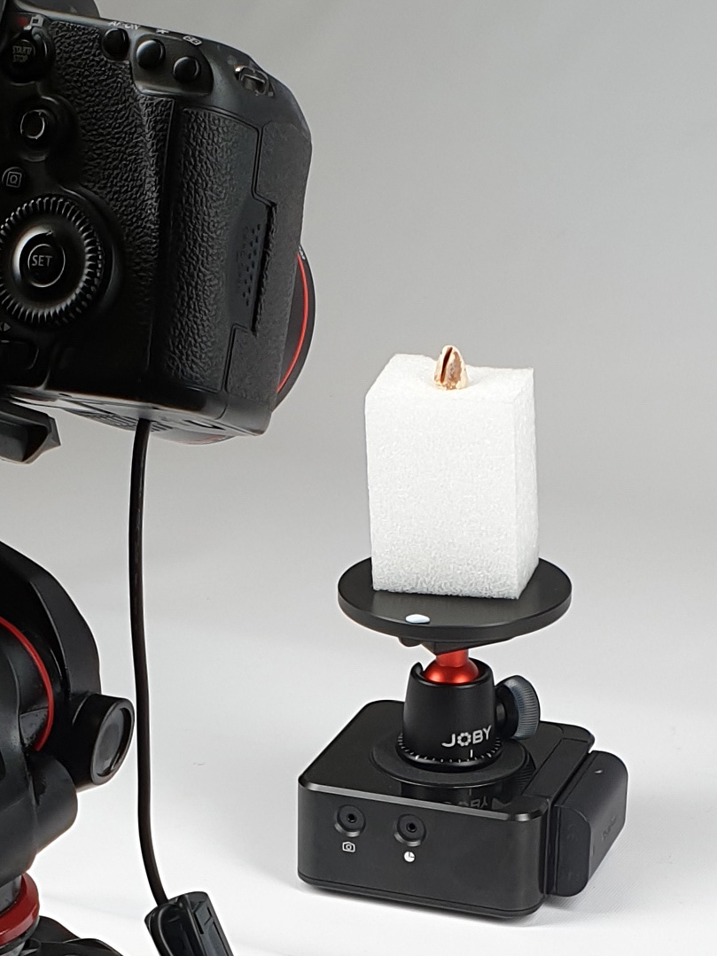
While this was functional for larger objects (15mm to 20mm on the full frame sensor) it suffered from a number of issues: the linear macro rail involved coarse and time consuming left/right alignment using the tripod head controls, and the 100mm macro lens is still at best a 1:1 lens so not ideal for the smaller objects of or under 10mm where typically less than 1/4 of the sensor would be utilised. The final solution involved a 2 axis macro rail, left and right for alignment and forward-back for focus. The final lens was a Canon 65mm macro with between 1:1 and 5:1 magnification, although for these objects no more than 3:1 magnification was actually used. 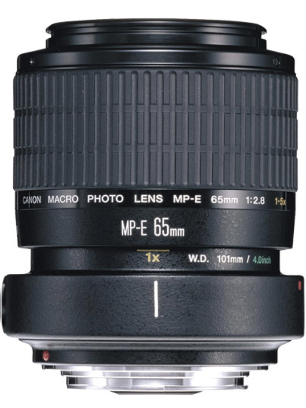
There are alternatives to purchasing a relatively unusual 5:1 magnification lenses, for example the reverse lens approach. 
Since a full 3D model is required, the objects were each photographed in two orientations with typically at least 30% overlap. The shape of each object varies and different mounting arrangements were employed for each shape type. Critical of course is for the object not to move during a scan, although small vibration induced movement can be tolerated as it corresponds to a camera shift or tilt. A light box was used to both give higher levels of light so that a small aperture (increased depth of focus) can be achieved. It also removes lighting effects on the objects themselves allowing maximum opportunity to relight in the presentation renderings.  Capture
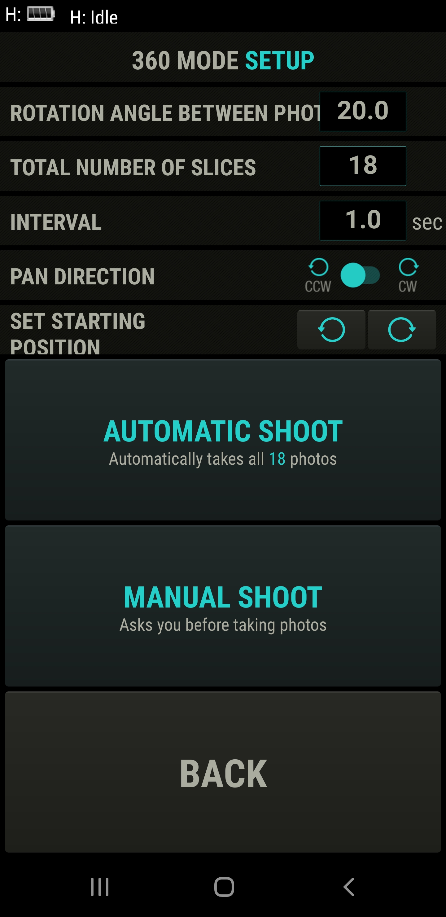
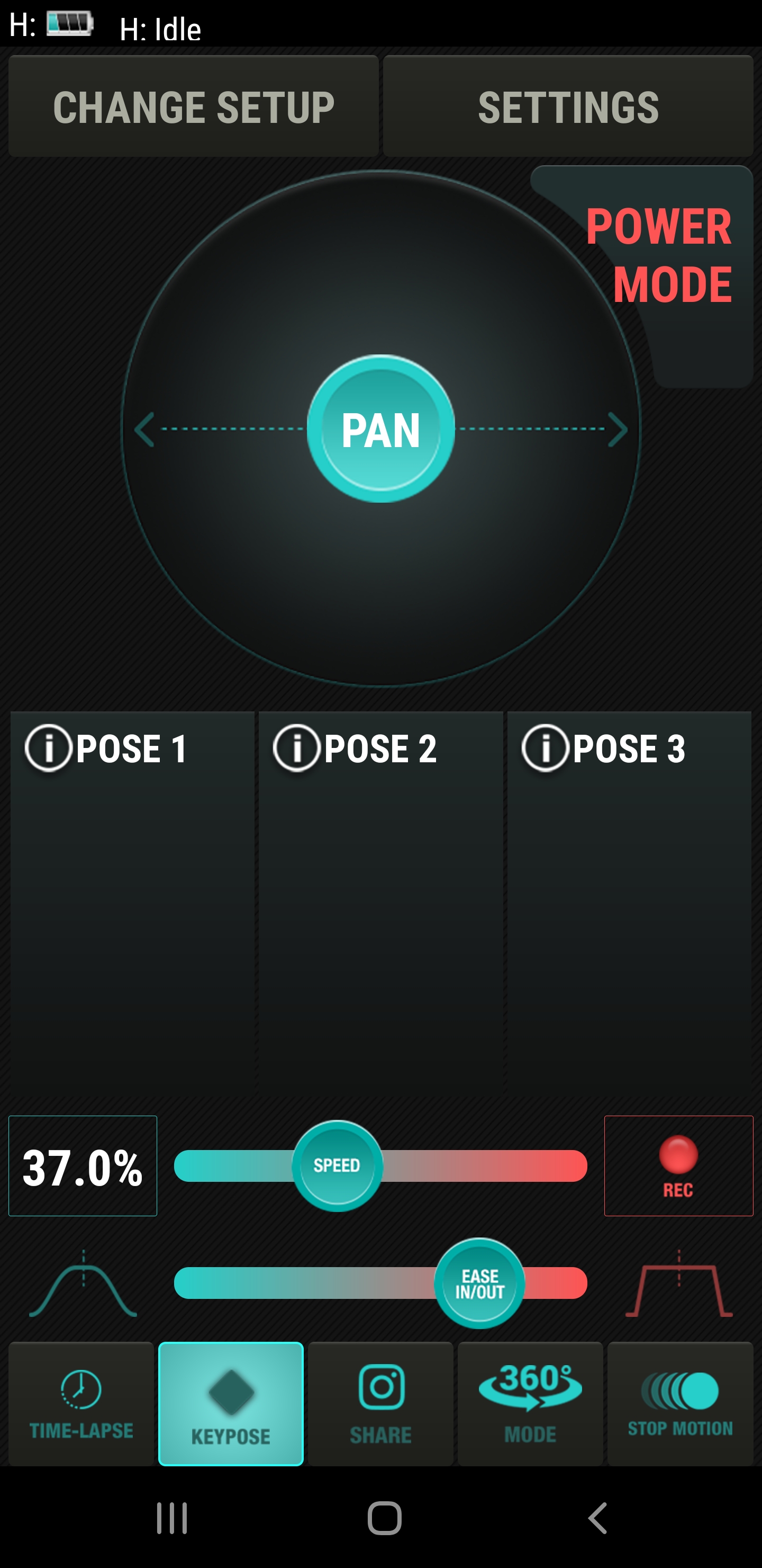
For 1:1 and 2:1 magnification, there was sufficient overlap of in focus regions and therefore sufficient feature point overlap by taking 20 degree steps in longitude and performing four 360 rings in latitude. Since the latitude range was typically 0 (equator) to 80 degrees this is also a 20 degree step size in latitude. In many case for the highest latitude only 30 degree steps were needed for sufficient overlap. Therefore each half scan required either 66 or 72 photographs. The camera was the Canon 5D Mk III (full frame). The automatic rotation was achieved with the Edelkrone Head One rotator unit. 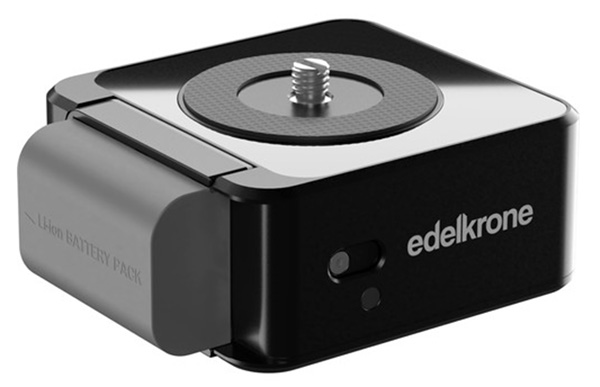
There was sufficient light in the light box for the maximum f16 aperture, while still maintaining a reasonable ISO 200 and 1/20 shutter speed. On each shot a decision was made as to the region to focus on, generally due to the shape of the object this was the closest surface to the camera. The macro rail was used to focus since this lens has no automatic focus capability. Even with automatic focus, macro lenses generally have significant focus breathing which is varying the focal length for each shot, not a good idea for 3D reconstruction algorithms. Finally, after focussing using a zoomed view on the LCD display, the shot was taken after any vibration had settled down. On average this whole process for a single shot took 15 seconds. In summary the process involves first setting the tripod height for the upcoming latitude scan, then for each longitude position:
Processing
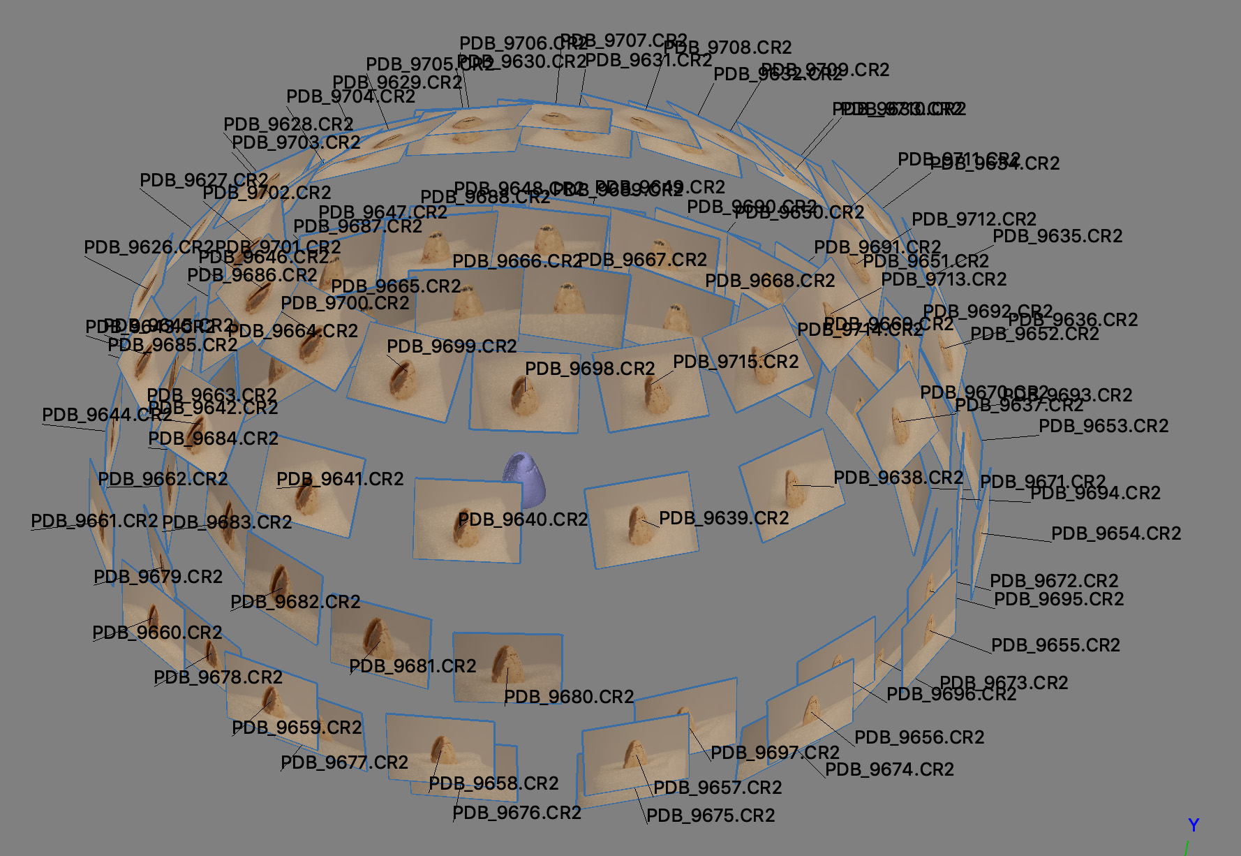
The upper and lower halves after the camera alignment process are shown below. Due to the shallow depth of focus, in general anything not on the object was well out of focus and no feature points were found. As such in most cases masking was not required saving a significant amount of human time. 
In general there was not sufficient overlap between the two halves for an automatic point based alignment and merge. Instead a number of matching markers were identified on each half and an alignment and merge by marker performed. Example shown below. 
The following shows the merged camera sets. In general better results were obtained by recomputing the dense point cloud after the merging process. 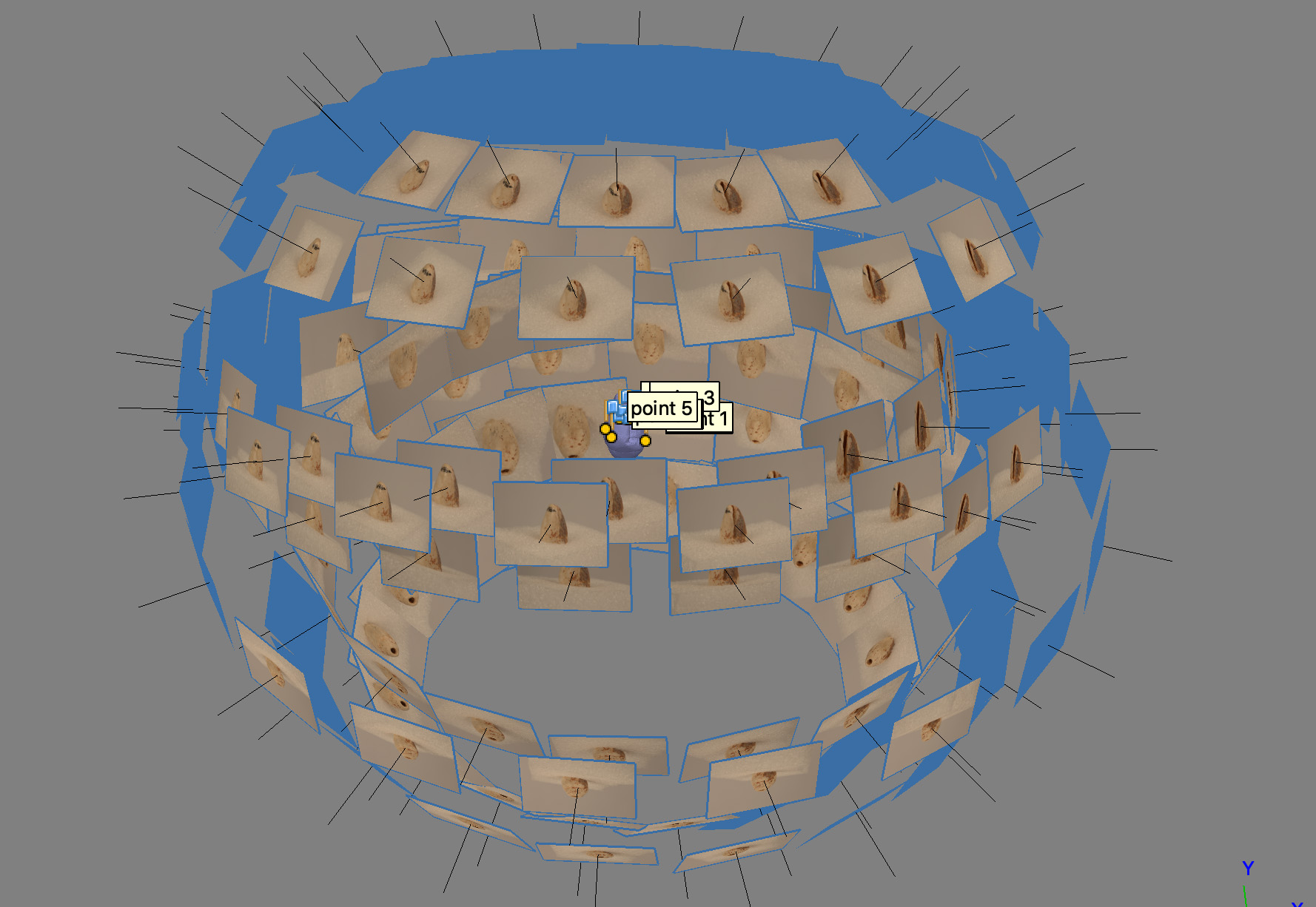
Finally the merged model. 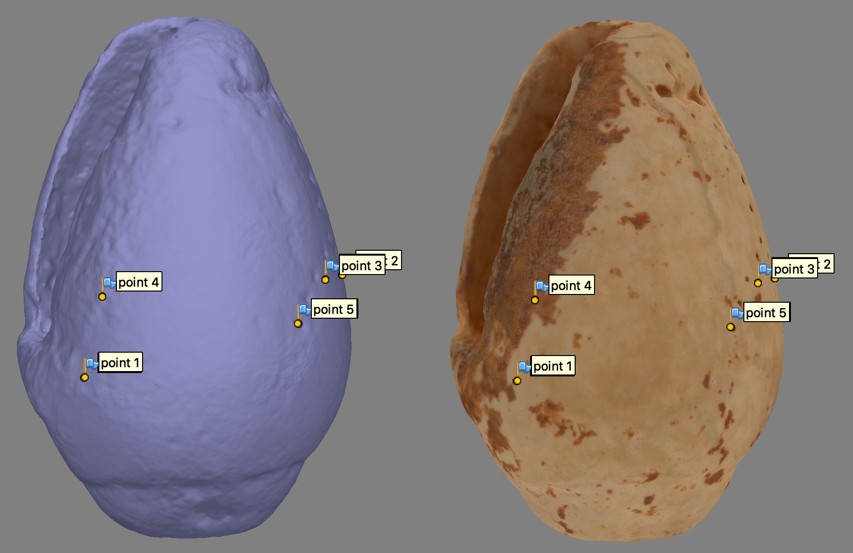
Typical project summary might be as follows. 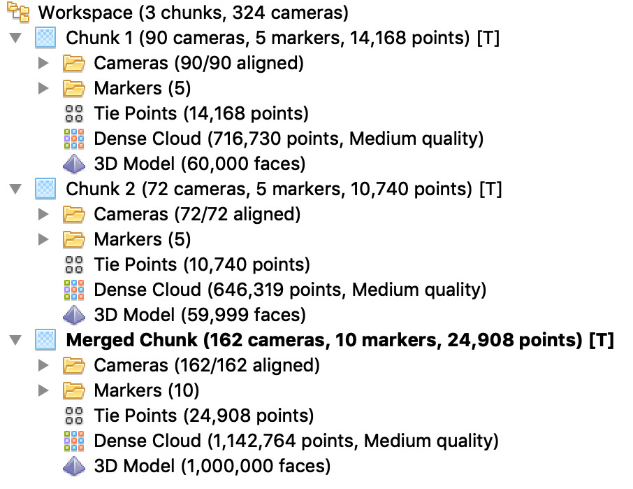
|