Organising unstructured networksWritten by Paul BourkeJuly 2004
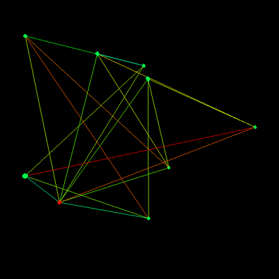
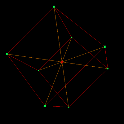
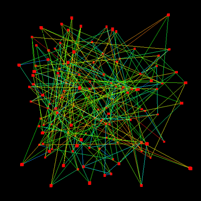
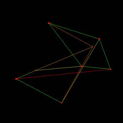
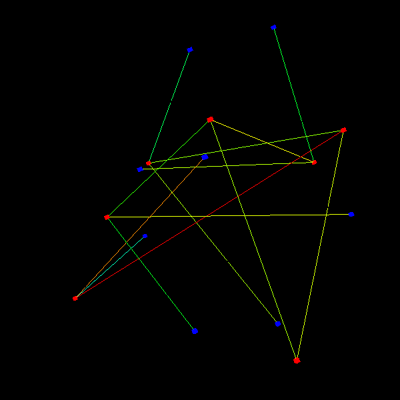
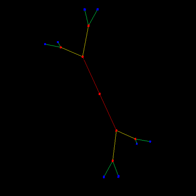
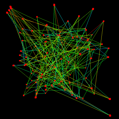
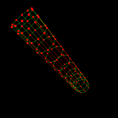
The following describes a way of automatically organising an unstructured network in order to visualise the underlying structure. An unstructured network will be defined as a set of nodes connected in pairs by linkages. Note that such a definition does not contain any geometric data, it is the position of each node that will be derived, in this case in three dimensions since that has much greater ability to avoid intersecting edges. Consider the network on the left, the same network is shown on the right where the structure (relationships between the nodes and connectivity) is rather more obvious. The nodes are represented by small squares or circles and the linkages are represented by line segments.
The desirable properties include: separating unconnected nodes as much as possible, avoiding crossed links, and the grouping of interconnected structures. This has been achieved by giving the nodes and linkages physical properties, namely charged particles for the nodes and extended springs for the linkages. The nodes are all give the same charge so each node repels all other nodes. The springs are given a zero rest length so they are always trying to bring nodes they join together. These simple physical attributes seem to arrange the networks in 3D space in such a way as to aid in an understanding of their structure.
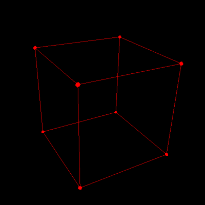
The network read by the software developed for this exercise is described by a list of linkages, in the simplest case a text file containing a list of node id pairs. For example the reader should be able to convince his/her self that a cube can be represented as follows 0 1 0 4 0 3 1 5 1 2 2 3 3 7 4 7 7 6 2 6 5 6 5 4 The nodes are initially assigned to random coordinates in 3D as shown on the left, after applying the forces described above and letting the system evolve the final stable result is shown on the right. Basically, the nodes move apart until the repulsive force from the charge matches the attractive force of the springs.
The spring forces are computed using Hookes law, that is, the attractive force is proportional to the length of the spring (zero rest length). The repulsive force on one node due to another from their charges is proportional to the inverse of the distance between the nodes. That is, if the nodes are very close they repel very strongly, distant nodes don't have much effect on each other. Each node applies this force to all others, this becomes a computational issue for large numbers of nodes. It so happens that the exact law for the spring force (constant, linear, quadratic) and the exact force law for the charges doesn't affect the resulting arrangement, it only affects the size of the structure.
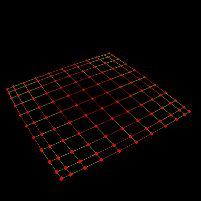
As an interesting side issue, the connectivity information required for the structures shown here is very efficient. In other words, this is a very compact way of storing the geometry.
|
