HarmonographWritten by Paul BourkeOriginal: August 1999, Updated July 2002, and April 2008
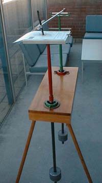
The two pendulum harmonograph draws attractive patterns that arise from drawing the relative path traversed by two swinging masses as their motion is slowly damped. The resulting figures are called harmonograms or sometimes a Lissajous curve.
The harmongraph was pioneered by the French physicist, Jules Antoine Lissajous in 1857. The first harmonograph actually used a light beam on a screen instead of the pens on paper that are used today. Following the invention of the harmonograph it became a very popular device and was found in many homes. After the early 1900s it decreased in popularity and is rarely seen today.
Another device also called an harmonograph since it produces the same essential motion is based upon a platform suspended by each corner. The platform can be swung and twisted and a stationary pen draws a trace on some paper attached to the platform. Weights are often located at various positions on the table to produce different oscillatory patterns. One of the largest harmonographs of this kind can be found in the Science Centre and Planetarium, Wollongong, Australia. Andrew Purdam has produced equations that allow one to explore the beauty of the harmongraph without building one....not that building one is any less satisfying. His equations are:
All initial amplitudes, frequencies (w) and phases (p) should be different and not integer multiples for the most complicated (interesting) patterns. In order for the amplitude to decay (not necessary but occurs in the real harmonograph) the amplitudes can decay as follows, where d is typically a suitable small positive number. This gives an exponential decay function.
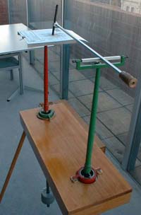
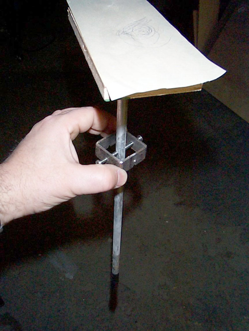
Contribution by Rick and Richard Speir
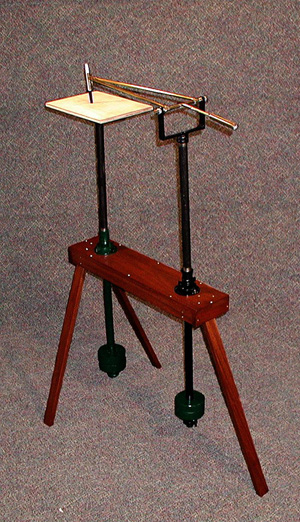
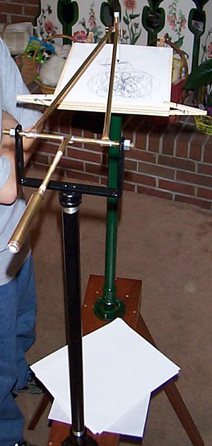
Contribution by Ed Mattson
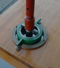
I was captivated as a child by a harmonograph at the old Oregon Museum of Science and Industry. It was a simple affair consisting of two giant pendulums hanging from the ceiling. I remember being frustrated because it was so popular I had to queue for ages to use it and not have time to see many of the other exhibits. Later, as an adult, I made a similar device that hung from the floor joists in my basement. As I was making my living as a woodworker at the time, I realised there was probably a market for such a fascinating device and a chance to wed it with some fancy woodworking. The problem was that I needed to think of a way to make something that did not have to be hung from a wall or ceiling because of the liability for a smashed foot if it were improperly installed. I finally thought of a way to make it entirely free-standing and portable. My first prototypes used crude home-made gimbals made from large washers with drilled dimples which rested on hardened screw points. With a little out-of-box thinking I realised the gimbals need not be at the top of the pendulums but could be in the middle, causing the drawing modules at the top to move in opposite direction from the weights at the bottom. Placing the pen arm and paper tray at the top also put the "business end" at an ideal height closer to the user. In the initial prototypes, the main problem to overcome was the forces generated by the heavy, swinging weights in the pendulums. Each had about 23kg of lead (which I melted down from shot) plus the weight of the pendulum structure and heavy wooden boxes that sealed the lead from the outside world. This led me to replace gimbals with captured automotive u-joints, which were far more stable and were inexpensive. They added a slightly greater decay factor, but the pendulum weight was sufficient to make this negligible. The other problem to overcome was the twisting and stress on the whole frame structure. I wanted to make it knock-down for portability but also easy to assemble without the use of a lot of tools. This required a certain mass in the various parts, but I avoided too much mass by coming up with a system of strong friction joints that were held together with knock-in wedges. The whole thing can be completely assembled and disassembled with just a mallet. The joints loosen slightly and slowly with use, but require just a tap on the wedges every couple weeks or so to tighten things back up. Also, there was just enough flexibility in the frame to have an unexpected effect. The energy of each pendulum transfers through the frame just enough to effect the other pendulum (both dampening and amplifying) and alter the pattern of the drawn curves. 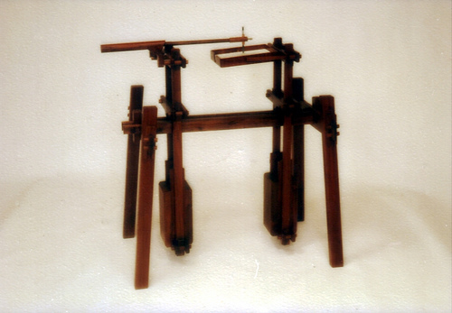
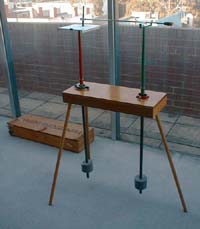
For visual effect, I wanted all these joints to have a sort of exposed, complex, high-tech look and the wood itself also had to be attractive but strong. I used some high quality, figured walnut which is plentiful in Oregon. I worked hard on an overall visual effect to complement the actual function of the machine. I demonstrated the harmonograph at two of the annual shows put on by the Guild of Oregon Woodworkers but was not prepared for the response! It drew huge crowds and gasps of wonder as it did its magical thing. Much time was spent with crowd control and device protection - especially from the excited kids! I lost count of the number of reams of paper of finished drawings given out. It was not just the drawing itself but the harmonious and mesmerising interaction of the parts of the machine that fascinated people as it swung away and drew the curves. The crowds were literally and unconsciously swaying in unison as they stood watching. I got a real chuckle as I overheard two elderly guys down on their knees inspecting and discussing the mechanics. They were saying things like, "The gyroscopes have to be in the boxes here but I just can't figure out how he's hidden the electronics." I just bit my tongue and pretended not to hear. Why deprive them of the mystery? |