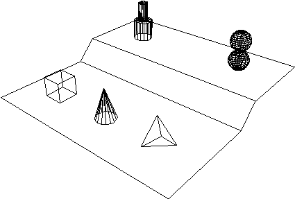
SCENEA proposed format for 3D geometric data interchangeWritten by Paul BourkeDraft 2, 29 August 1994 Introduction Anyone who has been involved in the conversion of three dimensional geometric data between software packages will appreciate the difficulties resulting from no single widely used file format of storing geometric information. At one end of the scale there are formats such as DXF which while being widely used is severely limited in the types of geometry it can support. At the other end there are quite powerful geometric descriptions such as RIB, these suffer because of the difficulty in using them for anything else except as input to a RenderMan renderer. The other formats which exist tend to have been designed by a particular application author with his/her application in mind, the format has then been used by others often in application areas for which it was never intended nor designed for. The result of having no clear winner for an interchange format for 3D geometry has resulted in many of the undesirable characteristics evident in the industry that deals with 3 dimensional models. Users tend to do their modelling from scratch since there are few successful geometric library collections that anyone can use with their favourite software. Users are not able to freely pick and choose from a variety of modellers, renderers, and animators. rather they need to restrict their activities to a narrow range of packages dependent on the translation software available. Collaboration and model sharing is difficult, this is particularly noticeable when it comes to sharing models over the internet. While the storage of 3D geometric data is acknowledged to be more problematic than image storage, it is interesting to note the situation that exists in the industry for the interchange of images. There are formats such as TIFF, GIF, and JPEG which do not have serious feature restrictions for the vast majority of users, there are readily available viewers, converters exist for packages or other less common formats, and the above are available on all the major hardware platforms. As a result, if someone wishes to supply a copy of an image to some other site there is good chance that this will be a trivial and successful exercise. On the other hand, reliably distributing a 3D model to another site is only likely to be successful in special and well thought out situations, generally both sites would need the same software package! It is this issue that the SCENE proposal attempts to address.
The SCENE format The following is a proposal of a file format for the electronic interchange of three dimensional geometric information. The desirable characteristics this format will be designed around are outlined below (they are not in order of importance). It should be noted that some of these guidelines are mutually exclusive and thus the resulting format will be a compromise between some of these characteristics. * There should be a wide range of geometric primitives. This generally means that the geometry from other descriptions/formats can be incorporated with no or at least minimal primitive decomposition. * Each geometric primitive should be as general as possible. For example, there is no cylinder primitive (same radii at either end) as it is a subset of a cone (end radii are different). * The description of the geometry should be efficient. The files will be transmitted over bandwidth limited channels and from experience many models contain a large amount of geometric information. * The format must be extensible so that new primitives can be added. The primitives described later in this document are by no means a comprehensive list. In particular, there are no functional surface types such as bezier surfaces. These have been intentionally omitted from this initial release in an attempt to create an initial stable base. * The release of the format includes support software and algorthims. This will allow users to employ the format immediately as well as provide a basis for future development. * The format should not place an undue burden on software developers. This is an attempt to encourage developers to create tools for manipulating and translating models described by the format. * The files must be easy to read by humans. No matter how good the software tools are there will be times when a visual analysis or modification of the file by humans may be necessary. Developers using the format should be encouraged to format the files so as to aid human readability.
Initial format description A SCENE formatted file consists of a number of "lines" of text. Each line consists of a number of "words", words are separated by white space (spaces, tabs, returns, newlines). A line that is considered significant starts with one of a number of keywords, these keywords will then have a number of arguments depending on their particular definition. All text, including keywords, is case sensitive. The set of initial keywords are outlined below along with a description of their parameters. # text A special (enforced) comment. Not strictly necessary but included due to existing conventions and therefore readability. The comment extends to the end of the line. Any line not starting with a keyword and not part of a keyword parameter list is assumed to be a comment. This allows future keyword (mainly geometric primitive) additions to the format without the existing support software breaking. Of course these new features will be ignored by earlier software implementations. Material name surface red green blue specularity transparency Definition of a named material. All the arguments are required. Material names should be kept to a minimum for file efficiency except where it compromises human readability. A surface could be anything but is intended to refer to physical types with distinct light interaction behaviour such as "plastic", "metal", "glass", etc. Colour is specified as red, green, blue triples, also known as rgb values. Each component ranges from 0 (black) to 1 (white). "specularity" varies from 0 (perfectly diffuse) to 1 (perfect specular reflector). Transparency ranges from 0 (opaque) to 1 (transparent). There are obvious omissions, (eg: textures) from the material definition, this is intentional and due to the large variation in the way packages (in particular rendering packages) support materials. It is intended that by providing named materials that the materials will predominantly be done independently of this format which concentrates on geometry. The material attributes provided are there primarily for modelling/previewing software as well as for simple rendering packages. Transformation name n transformations This defines a transformation which includes n operations from translation (TX, TY, TZ), proportional scaling (S), rotation (RX, RY, RZ), and mirror (MX, MY, MZ),. The transformations are performed in the order they appear, thus multiple (cumulative) transformations can apply. Rotation angles are specified in degrees and are positive if clockwise when looking along the positive axis. For example, the transformation list "5 TY -1 RZ 45 S 2 MX TY 1" will translate the object to which it applies by -1 unit in the y axis, rotate about the z axis by 45 degrees. mirror in the YZ plane, scale by a factor of 2, and finally translate back along the y axis by 1 unit. A default transformation exists called NONE which performs no operation and thus corresponds to the following transformation list 7 TX 0 TY 0 TZ 0 RX 0 RY 0 RZ 0 S 1 Note that there is only a proportional scaling, ie: you cannot specify SX, SY, and SZ scaling. This is to avoid object decomposition which would need to occur for many primitives, for example, spheres. Instance filename transformation Instances the contents of file, the transformation list applies to all geometry in the file. Recursive instancing is forbidden. The use of filenames is likely to be a major source of incompatibility across systems. SCENE itself does not place any restrictions on the length of file names, it does assume a directory structure which follows the UNIX file naming and directory rules. To assist in portability of files absolute references should never be used and file names should be entirely in lower case. For a even higher level of compatibility, file names should be restricted to 8 characters or less. Point name material transformation n P1 P2 .... Pi .... Pn Definition of a series of vertices in space. n >= 1 Line name material transformation n P1 P2 .... Pi .... Pn Definition of connected line segments made up of a number of vertices in 3 dimensions. n >= 2 Polygon name material transformation n P1 P2 .... Pi .... Pn Definition of a polygon made up of a number of coplanar vertices. Polygons, and all subsequent planar primitives, may be convex or concave. Polygons with holes can be represented by coincident seams.
n >= 3
 Definition of a irregularly spaced rectangular grid defined by an n x m matrix of vertices. The polygons formed by such a grid must not overlap. The 4 corners of a grid need not be coplanar as in almost all implementations the grid cells will be decomposed into triangular facets. n, m >= 2
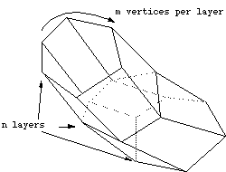
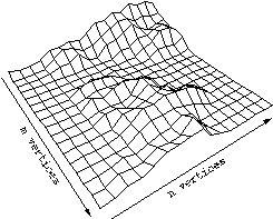 Definition of an extruded mesh with m vertices in each layer and n layers. Note that a polygon is a special case of grid where n = 1. As with a grid the polygons forming the mesh must not intersect. "capped" is TRUE or FALSE and are formed by polygons on the first and last layer, not on any in-between layers. The vertices forming each layer must be coplanar, the same as polygons. The interlayer polygons will be formed with triangular facets when exported. Note that a mesh can be used to represent both extruded and discretely lathed objects. n, m >= 2
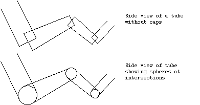
 Tube name material transformation capped n P1 r1 P2 r2 .... Pi ri .... Pn rn A tube is a series of connected cylinders of variable radius at the ends following a path through space. "capped" is either TRUE or FALSE and determines whether or not the ends and intersections are sealed. The tube is capped with disks at the ends and with spheres at the intersection vertices between two cylinders. Note that this behaviour at the intersections means that tubes of more than one cone segment are probably not intended to be viewed from the inside.
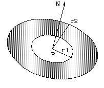
 n >= 2 Sphere name material transformation n P1 r1 P2 r2 .... Pi ri .... Pn rn Definition of a number of spheres, optionally each has a different radius. n >= 1 Disk name material transformation n P1 N1 r11 r12 .... Pi Ni ri1ri2 .... Pn Nn rn1 rn2 Definition of a number of disks centered at a point P with normal N, inner radius r1 and outer radius r2. These would be primarily used for caps to tubes (cones and cylinders) where r1 would be 0. The normal need not be a unit normals.
n >= 1
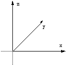
 Notes on the SCENE format * The coordinate system is right-handed as shown below. While it is not part of the format, it is suggested that the "front" view has the x axis to the right, the z axis upward, and the y axis into the projection plane. This would be the case for specific SCENE viewers or previewers. Translators would do the appropriate axis conversion when moving geometry into or out of the SCENE format.
* The units for SCENE are not explicitly set although meters would normally be
assumed. If other units are used then it should be explicitly stated in a
comment at the top of the SCENE file. Such units can be easily accounted for by
instancing the files with a named transformation with the appropriate scaling
value. For example to instance a file called "chair" described in inches into a
model using millimeters transformation inchtomm 1 S 25.4* All the parameter lists are unlimited in length although there may be minimum values. For example a tube must have at least two vertices, one start and one end point. While the format does not place restrictions on the length of the entities, consideration should be given to readability. One general rule is to avoid long lines which can make visual inspection by humans difficult. * All surface based primitives are considered two sided with infinitely thin surfaces. If a particular package only deals with single sided polygons then they should be converted into thin extruded sheets of a user chosen (minimal) thickness or into two polygons with flipped vertex ordering whichever is most appropriate.. * Aspects of certain primitives may be unrealisable by some software, in particular rendering packages. These geometries should never be ignored but rather turned into something that can be represented. For example, if necessary, points should be converted to spheres of a user specified radius, lines should be converted into capped cylinders, again of a user specified radius. * Implementations of the format should be forgiving where possible. Parametric values will be coerced into legal ranges, the exact coercion has yet to be decided upon. For example negative radius values should be converted to positive ones. Colours should be wrapped (mod) into the 0-1 range. Incomplete parameter lists are treated as comments. Minimal software which would be provided as part of the format
Examples of source code demonstrating the following How to parse and analyse SCENE filesTranslators from the SCENE format into the following rendering packages Radiance, POV-Ray, RayShade, RenderManTranslators to the SCENE format from the following formats DXF, OBJ (Wavefront), THING, OFF (DEC), BYUViewers of SCENE models for the following environments Macintosh, DOS/Windows, X-Windows
Translators would be made available in the future from the native formats of
commercial applications. An initial release would probably include translation
from ArchiCAD, Upfront, Super3D, ModelView, MacPerspective
Widespread use of this format would encourage manufacturers to support it. In
reality though one would hope that the authors of public domain and shareware
applications would include SCENE export and/or translators. The initial
distribution would include SCENE export from Vision3D, a Macintosh based 3D modelling package Example of a SCENE formatted file
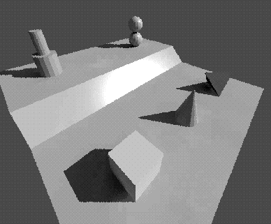
# Demonstration model described in the SCENE format

Material brownwood plastic 0.8 0.8 0.2 1 0
Grid stand brownwood NONE 4 2
        0 0 0   5 0 0   6 0 1   10 0 1
        0 10 0  5 10 0  6 10 1  10 10 1

Material bluetubes metal 0.1 0.1 0.9 1 0
Tube basepipe bluetubes NONE FALSE 2
        8 7.5 1 0.5     8 7.5 2 0.5
Tube basepipe bluetubes NONE FALSE 2
        8 7.5 2 0.25    8 7.5 3 0.25
The following are caps for the two above tubes.
Disk basepipe bluetubes NONE 2
        8 7.5 2 0 0 1 0.25 0.5
        8 7.5 3 0 0 1 0 0.25

Transformation conespace 3 S 0.5 TX 2.5 TY 5
Tube spike bluetubes conespace FALSE 2
        0 0 0 0.5       0 0 3 0

Put a tetrahedron on the lower level
Material greencolour plastic 0.1 0.8 0 1 0
Polygon tetrahedronface1 greencolour NONE 3
        2.5 2.5 1       1.5 1.5 1       2.5 1.5 0
Polygon tetrahedronface2 greencolour NONE 3
        1.5 1.5 1       1.5 2.5 0       2.5 1.5 0
Polygon tetrahedronface3 greencolour NONE 3
        2.5 2.5 1       2.5 1.5 0       1.5 2.5 0
Polygon tetrahedronface4 greencolour NONE 3
        2.5 2.5 1       1.5 2.5 0       1.5 1.5 1

Transformation boxspace 3 S 0.5 TX 2.5 TY 7.5
Material concrete plastic .5 .5 .5 0 0
Mesh abox concrete boxspace TRUE 2 4
        -1 -1 0         -1 1 0          1 1 0         1 -1 0
        -1 -1 2         -1 1 2          1 1 2         1 -1 2

Transformation ballspace 3 TX 8 TY 2.5 TZ 1.5
Material clearred glass 1 0 0 0.5 0
Sphere balls clearred ballspace 2
        0 0 0 0.5       0 0 1 0.5

# End of the SCENE file
|
