Geometric representation using
QuickDraw 3D meta files
Written by Paul Bourke
August 1995
Introduction
This note discusses the representation of 3 dimensional geometry using
the QuickDraw 3D meta file format. It is written primarily for those
wishing to support the format for geometric interchange. The comments
within are entirely my own and are a result of my work and experience
in 3D geometric data interchange.
Only geometry is discussed, camera attributes, lighting
effects, and other state characteristics will be left to the
reader to explore, see the more complete description of the
QuickDraw 3D meta format.
Style
Like many interchange formats, QuickDraw 3D will at times be created
and read by humans. At times it may be necessary to create special
geometries by hand because a suitable modeller is not available. At
other times it is necessary to view the files to debug errors or problems.
It is therefore suggested that a style be adopted to facilitate the
human parsing of QuickDraw 3D meta files. As will be seen in the examples
below, liberal use of indenting aids in the interpretation of the structure
and is thus highly recommended.
Coordinate system
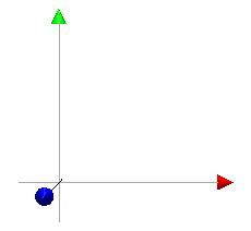
The QuickDraw 3D coordinate system is right handed, if the x axis is
considered to be to the right then the y axis is up and the z axis is
out of the page. The axis along with the meta file that produced it
are shown below.
 QuickDraw 3D meta file
Comments
All interchange formats tend to have a comment facility, this acknowledges
that at some stage a human may view the file and such comments may
be useful. Comments are often used to identify particular objects by
name or to clarify parts which may be confusing.
A comment is everything on a line to the right of a hash symbol
# This is a comment
The header
QuickDraw 3D meta file readers seem to expect some header information,
it is hard to imagine why this should be so. Interpreters in my opinion
be as fault tolerant as possible and not insist on such conventions.
In any case, the minimal header is as follows:
3DMetafile ( 0 0 Normal toc> )
Point
A point is of course just a single (x,y,z) triple, it is the most
primitive object. A green point at the origin can be defined as
Container (
	Point ( 0 0 0 )
	Container (
		AttributeSet ( )
		DiffuseColor ( 0 1 0 ) # RGB value
	)
)
There is also a marker primitive, this is a bitmap and always
faces the camera. While useful in many situations, I don't consider
it to be scene based geometry.
Line
A line is just described by its two end points.
Container (
	Line (
		0 0 0
		10 0 0
	)
	Container (
		AttributeSet ( )
		DiffuseColor ( 0 1 0 )
	)
)
The above describes a line from (0,0,0) to (10,0,0), the line
is green (r,g,b) = (0,1,0).
PolyLine
A PolyLine is a number of line segments defined by an ordered list of
vertices.
Container (
        PolyLine (
		3 # number of vertices
                0 0 0
                10 0 0
		10 10 0
        )
)
A PolyLine is not automatically closed, it does not represent
a surface. This is used mainly as a more efficient method of specifying
curves rather than as lots of Line primitives.
Ellipse
The ellipse is another primitive which is only a border. It is defined by
its major and minor axis and an origin. For a "solid" version of this see the
Disk primitive.
Container (
	Ellipse (
		1 0 0 # major axis
		0 1 0 # minor axis
		0 0 0 # origin
	)
)
Triangle
A triangle is the simplest primitive.
It describes a 3 vertex facet, alternatively, the surface enclosed
by 3 intersecting lines.
Container (
	Triangle (
		0 0 0
		10 0 0
		10 10 0
	)
	Container (
		AttributeSet ( )
		DiffuseColor ( 0 1 0 )
	)
)
This is the most practical of surface types for the vast majority of
interchange purposes. QuickDraw 3D has the usual convention for defining
the vertices in a particular direction when the surface is part of a
closed body. The vertices should be defined in an anticlockwise direction
about the "outward" pointing normal of the body.
Polygon
The "simple" polygon primitive can be used for all convex facets with
3 or more vertices and without holes or crossing edges.
Container (
	Polygon (
		4 # number of vertices
		0 0 0
		10 0 0
		10 10 0
		0 10 0
	)
)
A polygon is always closed, it is not necessary to replicate the last vertex.
Polygons can also be used to represent triangles, the number of vertices
being 3. Why then have the triangle primitive? The overhead for using
polygon instead of triangle is the few bytes necessary for the length.
The vertices making up the polygon are assumed to be coplanar. Failure
to be coplanar normally impacts on the shading calculations when rendering.
GeneralPolygon
This supports non trivial polygons, namely, they can be convex and
may contain holes.
What is solid and what are holes is determined by the even-odd rule.
That is, project a line from a point to the left say, if the number of
edge intersections is even then the point is part of a hole. If the number
of intersections is odd then the point is solid.
Each polygon boundary is called a contour, within the description the
number of contours are defined along with the number of points in
each contour.
The following example consists of a square polygon with a triangular hole.
Container (
	GeneralPolygon (
		2 # number of contours
		4 # number of vertices in first contour
			-2 -2 0
			-2 2 0
			2 2 0
			2 -2 0
		3 # number of vertices in second contour
			-1 0 0
			0 1 0
			1 0 0
   )
)
The vertices of individual polygons making up the GeneralPolygon
are all assumed to be planar.
Of course a Triangle and Polygon can be represented as a
GeneralPolygon with 1 contour.
TriGrid
A TriGrid is a 2D matrix of vertices forming a triangular grid.
It is particularly good for representing facet based surfaces.
Container (
	TriGrid (
		2 # number of row vertices
		4 # number of column vertices
		0 1 0
		2 1 0.1
		3 1 0.2
		4 1 0.3
		0 -1 0
		2 -1 0.1
		3 -1 0.2
		4 -1 0.3
	)
)
Note that because the grid is triangulated there is no problem with non
planar facets. Normally one would ensure that the vertex positions don't
result in overlapping edges.
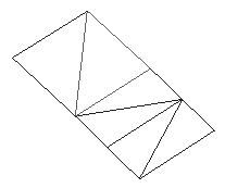
The above is shown below
Box
This defines a rectangular parallelepiped by 4 vectors, orientation,
major and minor axis, and origin.
A cube would have the magnitude of the orientation, major, and minor
axis all the same.
Container (
	Box (
 		1 0 0 # orientation
  		0 2 0 # major axis
  		0 0 3 # minor axis
  		0 0 0 # origin
	)
)
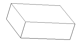
The above 1,2,3 box is shown below.
This is a very general way of representing a parallelepiped, although
it is a bit clumsy for many applications, often it is easier to create
such forms using the Mesh primitive.
Mesh
The mesh primitive allows you to specify a number of vertices for
an object and then describe polygonal faces using those vertices. It is
an efficient way of describing facet based forms which share common set of
vertices. Holes are specified by using a negative number of contours, the
hole is added to the previous polygon that was not a hole.
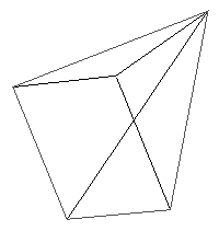
The following describes a pyramid.
Container (
	Mesh (
		5 # nVertices
			0 0 0
			0 10 0
			10 10 0
			10 0 0
			0 0 10
		5 # number of faces
		0 # number of contours
			4 0 1 2 3
			3 0 3 4
			3 3 2 4
			3 2 1 4
			3 1 0 4
	)
)
Note: the vertex ordering starts from 0, the first number in the polygon
vertex list in the number of vertices.
The above example is shown below
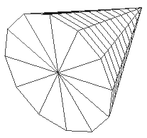
Cone
The cone primitive has 4 vector arguments.
The origin is the central point of the base of the cone.
The base of the cone is defined by two vectors, major and minor axis.
The tip of the cone is defined with the orientation vector.
These parameters are shown in the comments of the example below.
Container (
        Cone (
                2 0 0 # orientation
                0 1 0 # major axis
                0 0 1 # minor axis
                0 0 0 # origin
        )
        Caps ( Bottom )
)
Disks can be made by setting the orientation to a zero vector.
Cones can either be capped, as above, or uncapped.
The above example is shown below
Cylinder
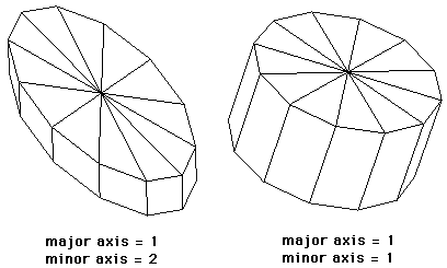
A cylinder is defined by 4 vectors, in a similar way to the cone primitive.
The origin is the center of the base of the cone, the major and minor
axis define the base, the orientation defines the extrusion of the base.
Container (
        Cylinder (
                1 0 0 # orientation
                0 1 0 # major axis
                0 0 1 # minor axis
                0 0 0 # origin
        )
        Caps ( Bottom | Top )
)
Cylinders can bave none, either, or both ends capped.
It is a shame that this description does not provide the
ability to specify different radii at each end of the cylinder.
Presumably a zero vector for the orientation would result in a two
sided disk.
Disk
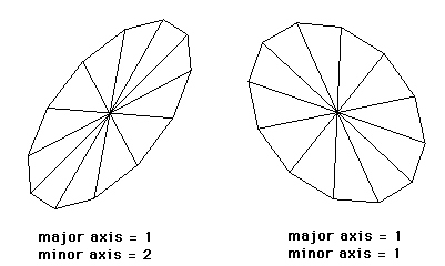
Beside the cone which can be used to define a disk, there is a specific disk
primitive defined by 3 vectors.
Container (
        Disk (
                1 0 0 # major axis
                0 1 0 # minor axis
                0 0 0 # origin
        )
)
Just as the Triangle is redundant given a Polygon so the
Disk would seem unnecessary. The data size savings are minimal,
any internal optimisation can still be performed by detecting Cones
and Cylinders that are essentially disks due to zero vector
orientations. Some example disks are shown below
A much more useful description would provide for an inner and outer radius
thus creating a disk with a hole in the center.
Ellipsoid
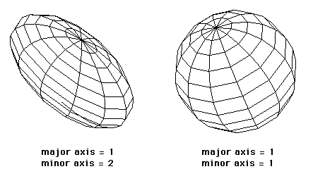
An ellipsoid (which includes the sphere) is defined by 4 vectors.
In general the ellipsoid provides for bulging spheres.
Container (
        Ellipsoid (
                1 0 0 # orientation
                0 1 0 # major axis
                0 0 1 # minor axis
                0 0 0 # origin
        )
)
If the orientation, major axis, and minor axis are all of the same
magnitude then the object is a sphere.
Two sample ellipsoids are shown below:
Torus
The torus is described by 4 vectors and a ratio.
Container (
	Torus (
		1 0 0 # orientation
		0 1 0 # major axis
		0 0 1 # minor axis
		0 0 0 # origin
		0.5   # ratio
	)
)
While it would seem useful to have a torus primitive it is rarely
used except for "novelty" purposes. When one does need a torus-like
shape the above description would probably not be versatile enough.
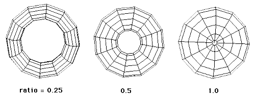
The ratio is the length of the major radius of the rotated ellipse
to the length of the orientation vector of the torus.
Examples of different ratios are shown below, all these have a unit radius.
A ratio less than 1 results in lobes squeezed in the orientation direction.
Ratios greater than 1 result in squashed lobes in the orientation direction.
NURB curve
NURB curves are Non-Uniform Rational B-spline curves. A rational
B-spline curve is a curve in 4D space, which has been projected down
to 3D space. Thus, the control points for a 3D rational curve have
four components - x, y, z, and w (usually known as the weight). For
such a point, the corresponding point in 3D space is (x/w, y/w, z/w)
Weights (w) are always positive.
Container (
	NURBCurve (
		3 # order
		4 # number of points
			0 0 0 1 # points
			1 0 0 1
			2 1 0 1
			3 0 0 1
		# knots, order + number of points
		# range from 0 to number of points - order + 1
		0 0.3 0.6 1 1.3 1.6 2
	)
)
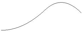
The above example is shown below
NURB patch
Non-Uniform Rational B-Spline (NURB) Patches.
It is beyond the scope of this note to describe the mathematics
behind B-Splines, the following example consists of a 3x3 grid
with the point at the origin off the plane of the other points.
The comments below do describe the number and range of the
required arguments.
Container (
        NURBPatch (
                3 # u order
                3 # v order
                3 # number of u points
                3 # number of v points
                       -2 2 0 1 -2 0 0 1 -2 -2 0 1
                        0 2 0 1  0 0 4 1  0 -2 0 1
                        2 2 0 1  2 0 0 1  2 -2 0 1
                # u knots, u order + num u points
                # range from 0 to number of u points - u order + 1
                0 0.2 0.4 0.6 0.8 1
                # v knots, v order + num v points
                # range from 0 to number of v points - v order + 1
                0 0.2 0.4 0.6 0.8 1
        )
)
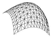
The above example is shown below
Transformations
Operators can be performed on geometry, some of these are operators are
Matrix Transform
Quaternion Transform
Rotate Transform
Rotate About Axis Transform
Rotate About Point Transform
Scale Transform
Translate Transform
An example of how to use these is
Container (
        Box (
                1 0 0 # orientation
                0 2 0 # major axis
                0 0 3 # minor axis
                0 0 0 # origin
        )
)

Translate (2 0 0)
Rotate (y .5)
Scale (1 0.5 0.5)
Container (
        Box (
                1 0 0 # orientation
                0 2 0 # major axis
                0 0 3 # minor axis
                0 0 0 # origin
        )
)
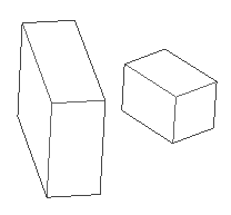
The example above is shown below
|