MSDL - Manchester Scene Description Language
IntroductionThe University of Manchester Computer Graphics Unit serves as a centre for computer graphics research, and over the years many novel graphics packages have been developed here. However as each researcher develops something, he or she is forced to cobble together a way of telling their application exactly what it is they want a picture of. Consequently a huge number of ways have been devised of positioning mirrored spheres over chess boards! In an attempt to reduce the duplication of effort, the CGU research group developed a scene language flexible enough to cope with the requirements of most graphics research programs. The language allows users to create a text file containing a description of a 3 dimensional scene, which could then be read by all users of the language. To encourage its use a parser was developed to actually read the language files, thereby minimising the amount of effort a programmer needs to expend to use a `standard' solution. The parser has been in use for some time now, and has proved a useful tool in graphics research. This report outlines the Manchester Scene Description Language (MSDL), designed for describing scenes which are to be used by a user's graphics application package. This document consists of a description of the language, a discussion of some example scenes, an outline of the process of generating the MSDL parser, and information on linking the parser to a users application. Included with the MSDL kit is a README file which includes a list of the distributions contents, and information on building the parser for different platforms. The parser is built using lex(1) and yacc(1) and consists of a C or Clibrary. The users application calls a function in this library to begin reading an MSDL file. As the parser reads the file it calls functions to generate object primitives in the scene. These functions are supplied by the user and placed inside his or her application. Consequently the application is not reliant on the type definitions used internally by the parser, and can define its own, copying the information provided by the reader into them. MSDL is available principally by anonymous ftp from the Manchester ftp site ftp.mcc.ac.uk (130.88.203.12), together with some sample MSDL scenes, and other Manchester sourced software. Information on the CGU, MSDL, other products and current research is available on the WorldWideWeb pages at http://info.mcc.ac.uk/CGU/MSDL/MSDL-intro.html. MSDL has been made available for use in the academic community. If you wish to use it for other purposes please contact us. It is supplied as-is, we do not guarantee its suitability for any particular use, and is not a supported product of the University of Manchester. However as we use it ourselves we would be interested in your comments and criticisms, which should be emailed to the Manchester general queries address, cgu-info@mcc.ac.uk, preferably with MSDL in the subject field.
The Manchester SDLSeveral scene description languages are in current use, and some of the features of these influenced the design of MSDL. Most of these file formats are keyed to the peculiarities of particular applications, and as MSDL was designed to be primarily used for research purposes no effort was made to make it compatible with these application languages.
Possibly the most popular of the non-application specific file formats examined was NFF. This was written with parsing to a local (more complex) file format in mind. Syntax that is close to NFF's is used where it is convenient.
An overview of MSDLThis section outlines the most important features of MSDL, leaving a more comprehensive treatment of the format for later in this document. We feel that an important logical separation should be made between the following purposes of any SDL:
This version of MSDL is concerned primarily with the first goal. However we feel that a `sample' camera definition should be included with most MSDL files, as without it the user may find it unnecessarily difficult to determine a reasonable view, given that he or she may not know what scale the scene is defined with. To that end MSDL allows an optional view definition, which the application may ignore if it wishes. MSDL files are plain text files, designed to be created both by users and their applications. Consequently it is possible to process MSDL files using other programs. Using pre-processors such as cpp &m4 the user can build up libraries of standard objects, which are #include'ed into specific scenes. However, for flexibility, we have included the ability to place C-style comments inside MSDL files without having to use a pre-processor. The ability to assemble standard libraries of objects leads to the notion of three ways to describe an object, each of which has a language keyword associated with it:
Other commands allow the user to manage surface properties, and transformations in the same manner.
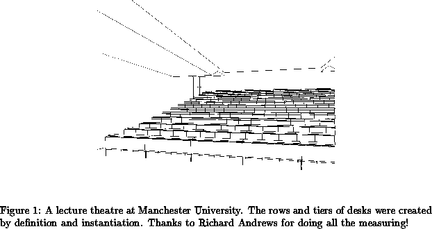
This define and instantiate approach allows an MSDL user to easily create
scenes which contain large numbers of repeated objects.
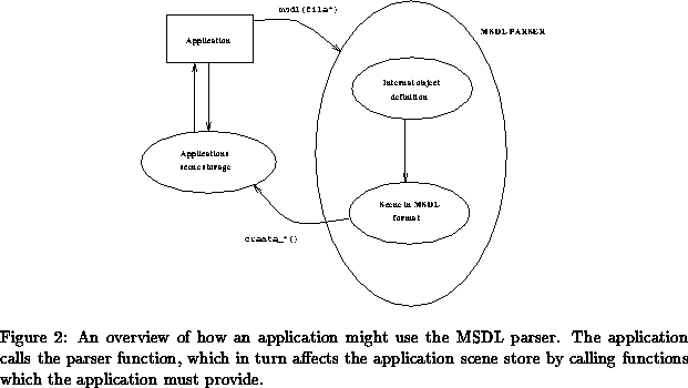
Figure
A users application employs MSDL by calling a function provided inside the parser supplied in this package. This function (msdl()) loads an MSDL text file into its internal store. It then processes the scene, to take into account the effects of instantiating objects, to determine the collection of objects which the application needs to know about. The parser then goes through each of these objects, calling a corresponding create() function. These functions are supplied in the distribution as skeleton code. When the user writes his or her application they fill in these skeleton routines, to perform something meaningful to their application. For example MSDL scripts can contain NURBS surfaces. However some applications may not be able to cope with these, and so will wish to convert them to something convenient for their internal use. So the application programmer could write a NURBS tessellation routine, which is called inside the create_nurb() function, to generate something for the applications use.
This process is described graphically in figure
Finally it is worth pointing out that the MSDL parser passes the information contained in the script onto the reading application. If the application chooses to use the data in the file for different purposes (for example an application might want to use the specularly reflecting information for something else) then the parser will be none the wiser. This means that users wishing to generate portable MSDL files have to ensure their applications uses the information consistently. The next section discusses the way in which a user describes a scene in the MSDL language. Following that is a short section on generating some sample scenes. The final sections of the report cover the information an application programmer wishing to link the MSDL parser into his or her system needs to know.
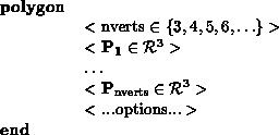
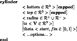
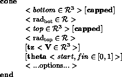
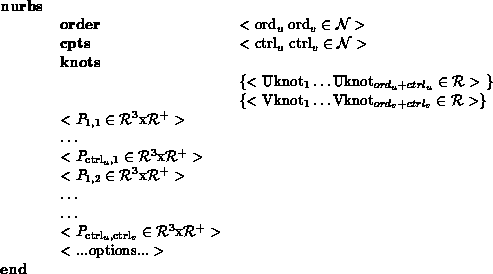
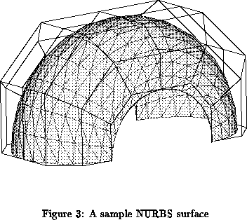
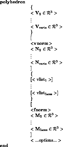
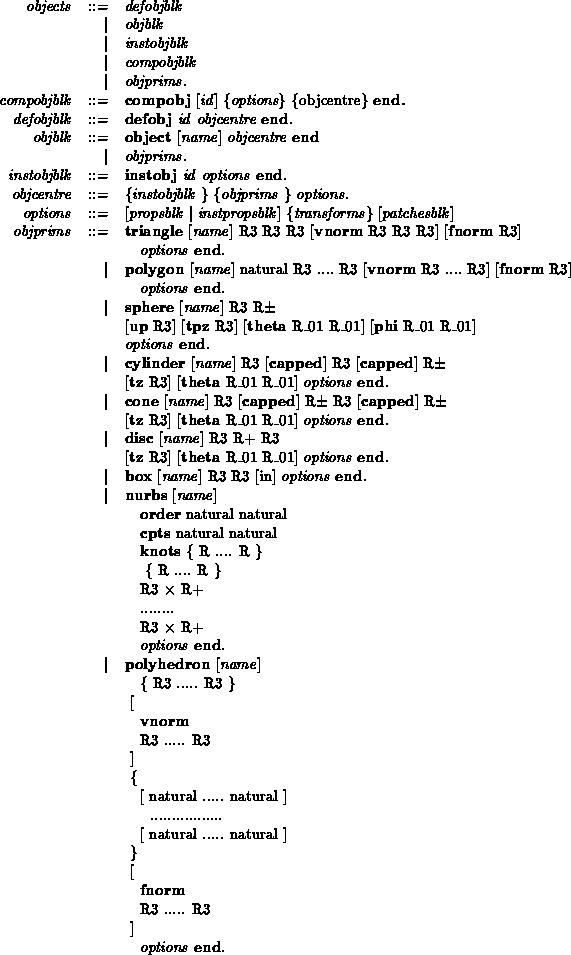
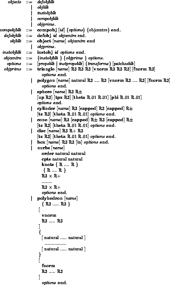
Object PrimitivesMSDL allows the user to define objects which can be grouped, transformed and have properties attached to them. These objects are defined in terms of primitives, which can be polygons, triangles, spheres, cylinders, cones, discs, boxes, NURBS and polyhedra. This section consists of a definitions of the different primitives, followed by a BNF syntax. Examples of how on might create one of the primitives is given in typewritten font.
Throughout this report, keywords are shown in boldface, parameters are
delimited by
The
Again, we see
So if we were defining a triangle, with the vertices normals define we could write something like the following : triangle 0.0 0.0 0.0 5.0 0.0 0.0 0.0 3.0 0.0 vnorm 0.0 0.0 1.0 0.0 0.0 1.0 0.0 0.0 1.0 end Let's take a look at the rest of the object primitives available:
Objects
Object Transformations
As mentioned earlier, the user can apply transformations to any of the objects.
The transformations will be stored hierarchically - i.e., they should be
applied
to all objects or object primitives that make up the objects block in
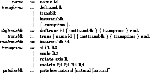
which they appear (see the BNF grammar, and section The various transformation options are outlined here:
Note that if the user wishes to scale or rotate an object about a particular
point
As mentioned earlier, the option to assign names to (presumably complex)
transformations, for ease of use elsewhere in the MSDL, has been included. The
precise syntax for this is shown in the BNF grammar in appendix An example transformation might look like
rotate x 20.0      /* Rotate by 20 degree around X axis */
scale 1.0 2.0 1.0  /* Stretch in y */
Composite objectsIn creating any complicated scenes you will probably want to perform operations (such as rotations) on groups of objects. To allow you to do this MSDL lets you to group a sequence of objects into composites.
MSDL allows you to group any number of objects into a named group. In
addition MSDL composites can contain other composites, to generate a
hierarchy. This hierarchy is communicated to the parent application by use
of the create_comp() and end_comp() functions. (See
section A BNF extract for the a composite object would then look like:
We might then wish to create a composite object by writing :
compobj chair

/* Rotate the entire chair by 90 degrees */
rotate x 90.0

instobj legs
instobj back
instobj bottom
end
Object Syntax
We want to define a grammar to specify the syntax of this part of the MSDL. The
full grammar for the MSDL can be found in appendix
Again, this piece of BNF includes some ambiguous parameters; these are:
Surface Properties
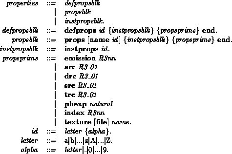
Surface Property PrimitivesThe user needs to be able to associate surface properties with object primitives. As mentioned earlier, one can define three different types of property block; one that associates a name with a particular set of attributes (defprops); one that associates an object (and possibly a name) with a particular set of attributes (props); and one that merely instantiates an already existing set of attributes (instprops). Before looking at the syntax of how one goes about defining these sets of surface properties, let's consider the different properties we can assign to surfaces in our scene. Many of these properties should be assigned a default value if the user fails to provide one, but this is implementation dependent, and will need to be supplied by the user:
Objects in MSDL are normally defined in some hierarchy (that is you can group objects, and have groups of groups, and so on). If you assign a surface property to a group it will apply to all the members of the group EXCEPT for objects in groups which have that property already defined. As an example of this suppose we define a table which consists of a top, and four legs. If we define the table top to be white, group all the table together, then assign a `pine' property to the group, the table top will still be white.
Surface Property Syntax
Again, here is a piece of BNF grammar to specify the syntax of this part of the
language: Remember, we should be able to do three things; define only; define
and instantiate; instantiate only. (The full grammar for the MSDL can be found
in appendix
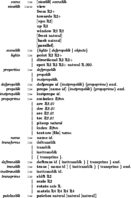
Explanatory note: The terminology used: Square brackets [....], refer to 0 or 1 occurrences of the bracketed item. Braces {....}, refer to 0 or more occurrences of the braced item, and the | symbol should be read as `OR'. Some undefined types appear in the grammar; these are defined as:
Note from the grammar that when defining a set of surface properties, we can instantiate simpler, previously-defined sets, rather than write all the information down again. Any conflict due to duplication will be resolved by taking the most recently defined value. Note that naming sets of surface properties defined using defprops is compulsory. As an example lets define a sample surface, which is highly specular, and has a texture file mapped onto it. To demonstrate its use we'll define the properties first, and instantiate them later in the scene.
defprops shiny_picture
	src 0.8 0.8 0.8
	arc 0.1 0.1 0.1
	texture file portrait.tif
end

....
  instprops shiny_picture
....
Lights
Lights with zero surface area (point light sources) are discussed here. Area
light sources are discussed in section Three types of light are supported by the language; point, directional and spot - these are specified in MSDL using text commands followed by parameters, which follow the syntax:
- A point light-source, located at
- As point, except positioned at
- This is a spotlight, situated at
Light Syntax
Here is a short BNF grammar to specify the syntax of this part of the MSDL.
(The
full grammar for MSDL can be found in appendix
Some of the terms that appear in this piece of BNF are not defined in the grammar as shown; these are:
So for example if we wanted to define a spot light pointing towards the origin we might define a light using :
spot
	0.0 100.0 0.0    0.0 0.0 0.0
	1.0 0.0 0.0 /* Red light */
	10 45
Other optionsMSDL has been used in the past extensively in radiosity applications. Consequently an option has been added to MSDL to allow some control over the way in which an application will subdivide a given primitive for radiosity calculations. The option
can be added to any primitive except polyhedra. This information is never used by MSDL, and is simply stored and passed to the routine the parser calls in the application.
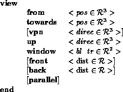
The ViewThe view syntax used in MSDL forms a superset of the information used by NFF, DKBTrace and PHIGS. MSDL files need not contain a view definition, and is provided merely for the users convenience.
The position from defines the projection reference point for the view frustum, whilst towards defines the view reference point - both are given in world coordinates. If the view plane normal (vpn) is not supplied, then it is taken to be the unit vector lying along the line (towards - from).
The up vector (which need not be normalized) determines the v-axis of
the
The window is defined in the The distances front and back are optional. They define the front and back clipping planes, and the distances are measured from from, increasing towards and beyond towards. They are included for compatibility with PHIGS. The keyword parallel is used to indicate that a parallel (as opposed to perspective) projection, is desired. A sample view then might look like
view
	from 100.0 0.0 0.0
	towards 0.0 0.0 0.0
	up 0.0 0.0 1.0
	window -10.0 -10.0 10.0 10.0
end
Generating MSDL files
As a résumé of the capabilities of MSDL we'll now discuss some simple
scenes We'll construct a simple scene from a collection of objects, beginning with a unit box. As we're going to use that several times we'll only define it.
defobj unitbox
  box
       0.0 0.0 0.0
       1.0 1.0 1.0
  end
end
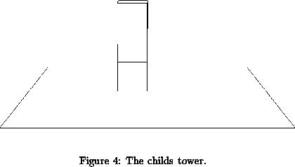
Now we can instantiate several of these building boxes, moving each up slightly to form a very simple model of a child's building box set.
instobj unitbox
  shift 0.0 0.0 0.0
end

instobj unitbox
  shift 0.0 0.0 1.0
end

instobj unitbox
  shift 0.0 0.0 2.0
end
To make the scene more interesting we can place surface properties in each of the boxes;
/* lowest brick in the tower */
instobj unitbox
  props
    drc 1.0 0.0 0.0
    texture file first_brick.tif
  end
  shift 0.0 0.0 0.0
end

instobj unitbox
  props
    drc 1.0 0.0 0.0
    texture file second_brick.tif
  end
  shift 0.0 0.0 1.0
end

/* top brick in the tower */
instobj unitbox
  props
    drc 1.0 0.0 0.0
    texture file third_brick.tif
  end
  shift 0.0 0.0 2.0
end
Just to make the simple scene more interesting we'll generate a floor, upon which the tower of bricks rests.
polygon
  4
  -4.0 -4.0 0.0
  -4.0 4.0 0.0
   4.0 4.0 0.0
   4.0 -4.0 0.0
end
Figure So that we can render the scene we'll place a spot light above the tower, pointing down at an angle
spot 0.0 0.0 100.0
     10.0 0.0 0.0
     1.0 1.0 1.0 /* Its a white light */
     10.0 60.0
Having exhausted the possibilities with simple objects lets move on to composite object; this example is a circular table, with a single central leg, and a square flat base which fixes it to the floor:
/* An example of a complex composite */

compobj coffee_table

  /* position the whole thing where we want it in the scene */
  shift 10.0 20.0 15.0

  /* The table top */
  cylinder
    0.0 0.0 0.0 capped 0.0 0.0 1.0 capped 1.0
    scale 10.0 10.0 0.1  shift 0.0 0.0 10.0
    instprops dark_wood
  end

  /* The leg */
  cylinder
    0.0 0.0 0.0	0.0 0.0 1.0	1.0
    scale 2.0 2.0 9.8  shift 0.0 0.0 0.2
    instprops  metallic_grey
  end

  /* The base */
  box  -2.0 -2.0 0.0    2.0 2.0 0.2
    instprops  metallic_grey
  end


end	/* coffee table */
Admittedly we haven't defined the properties `dark_wood' or `metallic_grey' yet, but we're assuming that's been done elsewhere.
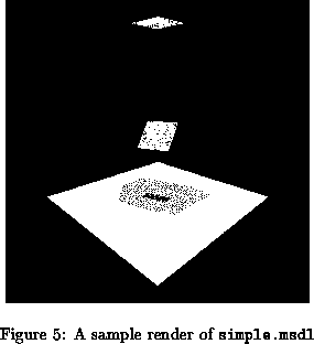
Included with the MSDL kit is a sample scene file, which was used as a test for
a radiosity/shadow algorithm here at Manchester. This file contains 3
polygons, one of which is a light source by virtue of having a defined
emission. Figure
Creating libraries of objectsIn any sizeable scene objects will need to be defined and instantiated many times, and in order to save time generating new scenes you may wish to generate a collection of pre-defined objects, which can be added to new scenes. Inside the pre-defined files use defobj to define and attach a name to a complicated object, so it can be instobj'ed by a scene. An MSDL file which has been constructed from existing definitions might look like:
#include "chairs"
#include "tables"

compobj
  name room
  instobj big_comfy_chair
    shift 10 0 10
  end
  instobj nice_coffee_table
    shift 5 0 5
  end
end
Then before passing this file to the MSDL reader you must use a pre-processor
to create a plain MSDL file. (See section As MSDL files are text files it is possible for user applications to write MSDL files. If you intend to use this method to produce libraries to be used in other scenes then we advise you prefix all names with an underscore (_) to help reduce any confusing name clashes. Building libmsdl.aThe MSDL kit consists of a collection of C routines which constitute an MSDL parser, together with this documentation and some sample MSDL files. The Makefile allows you to build a library for linking into your application, and can be compiled for either C or C. To compile for C simply type make. This will call lex(1), yacc(1) and cc(1) to generate libmsdl.a. To compile the library for Cedit the Makefile, changing the definitions of $(CC) and $(CFLAGS). A Cversion of the library will use new &delete to manage memory, which should avoid some of the memory leakage problems less forgiving Ccompilers can exhibit. Included with the library is a sample program which illustrates how you link this library with an application, and then call the parser. This can be generated by typing make tester. Once compiled the parser can be verified by typing tester simple.msdl, which will parse a trivial file. If there are no errors tester will terminate normally. If you wish to debug your applications reader define VERBOSE in $(CFLAGS), and recompile. The reader should display the information it is storing in its internal records for you to compare with your application. If you compile libmsdl.a with VERBOSE defined then the library will display debugging information as it fills its internal structures. This may or may not be of use to you! MSDL creates its own internal representation of the scene, which by default isn't free()'d at the end. (In earlier versions of MSDL its storage was used by the application itself, and so it made sense to keep it hanging around after parsing). If you wish to clean it up, as you probably should, define CLEANUP in the Makefile.
Linking your application to the MSDL readerThe MSDL reader parses the file, filling in its internal data structures as it goes. Once completed the reader traverses its structures calling the relevant create_star routines for each data item. These routines are defined as skeletons in application.c. It is anticipated that the application reading MSDL files will have its own internal data format for things like polygons, lights etc, which will need to be filled in. This data can be copied from the MSDL record Tobject* passed to the skeleton routine. (The definition of Tobject can be found in msdl_types.h, but is repeated in this document for your convenience.) If you are writing your application from scratch, and do not have existing object definitions you may wish to use the MSDL types. If you do ensure CLEANUP isn't defined when you compile. The create_view routine is only called if the MSDL file being parsed contains a view definition. Otherwise it is up to the application to choose a meaningful default. Each of these object routines is passed two parameters, and takes the form void create_polygon (Tobject*, Tmatrix ); The second item is the global transformation which may need to be applied to the object.
The MSDL structures are hierarchical, that is
transformations applied to node structures need to be applied to leaf items.
As the user application may not employ a hierarchical store the
global transform is accumulated for the application and passed as the
second parameter.
In a hierarchical application this can be ignored, and
only the transform stored inside the Tobject copied.
When the MSDL parser wishes to indicate to the application that the following objects are children of the previous object (i.e., it is stepping one level down in its tree) it calls create_comp(), and calls end_comp() when stepping back up. This should allow hierarchical applications to generate the correct data. Once the relevant create routines have been written and linked into your application, your program needs to call the function msdl(FILE *) to start the parser reading the relevant file. So, to summarise, in order to enable your application to read MSDL files you will need to;
Creating objectsThese routines are supplied as skeletons in application.c. Most applications will not be able to cope with all the primitives defined in MSDL, these applications should leave the relevant create functions as skeletons.
As discussed earlier all the functions concerned with creating objects have 2 arguments passed to them. These are a pointer to the object (Tobject*) and a global transformation matrix. The transformation stored in an object is only intended to be applied to that object and not to it's children and parents. The transformation matrix given is one which would put the object in the correct place if it's parents are ignored. The object is a structure which contains all the information gathered about the primitive, and is of the form:-
typedef struct object {
     .... /* Internal store removed for clarity */

     Tstring            name;        /* what's it called                  */
     Tsprops            sprops;      /* surface properties                */
     Tmatrix            trans;       /* transformation matrix             */
     Tptchs             psplit;      /* 3x4, 4x5x6 or what ?              */

     union {                            /* specific stuff */
         struct {                 /* polygon-specific stuff */
             Tpolydat        vvnfn;
         } polg;

         struct {                 /* tri-strip specific stuff */
             Tpolydat        vvnfn;
         } tri;

         struct {                /* sphere-specific stuff */
             Tpt3       centre,         /* centre                           */
                        up,             /* N pole (from centre) vector      */
                        tpz;            /* THETA=PHI=0 (from centre) vector */
             Tfloat     radius;         /* the radius                       */
             TThetaPhi  theta,          /* THETA start and finish           */
                        phi;            /* PHI start and finish             */
         } sph;

        struct {                /* disc specific stuff */
             Tpt3       centre,         /* the centre                       */
                        normal,         /* the surface normal               */
                        theta_zero;     /* the vector indicating theta zero */
             Tfloat     radius;         /* the radius                       */
             TThetaPhi  theta;
        } disc;

         struct {               /* cylinder specifics */
             Tpt3       top,            /* the top                          */
                        bottom,         /* the bottom                       */
                        theta_zero;     /* vector indicating theta zero     */
             Tfloat     radius;         /* the radius                       */
             Tbit       tcapped,        /* is the top capped                */
                        bcapped;        /* is the bottom capped             */
             TThetaPhi  theta;
         } cyl;

         struct {               /* Cone specifics */
             Tpt3       bottom,         /* the bottom                       */
                        top,            /* the top                          */
                        theta_zero;     /* vector indicating theta zero     */
             Tbit       bcapped,        /* is the bottom capped?            */
                        tcapped;        /* is the top capped ?              */
             Tfloat     bradius,        /* the radius at the bottom         */
                        tradius;        /* the radius at the top            */
             TThetaPhi  theta;
         } cone;

         struct {               /* NURBS specifics */
           Tpint        order_u,
                        order_v,
                        no_cpts_u,
                        no_cpts_v;
           Tfloat       *knots_u,       /* an array of the u_knots          */
                        *knots_v;       /* an array of the v_knots          */
           Tpt4         *cpts;          /* an array of u&v control points   */

         } nurb;

         struct {               /* Polyhedron specifics */
           Tpolydat     vvnfn;          /* verts, vert_norms, face_norms    */
           Tfarray      flist;          /* the faces                        */
         } polh;

         struct {               /* Box details */
           Tpt3         bl,             /* bottom - left                    */
                        tr;             /* top    - right                   */
           Tbit         in;             /* is it pointing inwards           */
         } box;
       } spec;                /* specifics for this object type */
   } Tobject;
(This type, and all the structures used by it are defined in msdl_types.h). Although most of the definition should be self-explanatory a few points are worthy of note. The type Tpolydat is a structure containing 3 Tpint's and an array of Tpt3's. The Tpints indicate how many vertices there are, how many vertex normals there are ( either equal to the number of vertices or none ) and the number of facet normals . The array contains these points and vectors in that order. i.e. the first facet normal will be stored at vvnfn.data[ vvnfn.no_verts+ vvnfn.no_vnorms]. The type Tfarray contains an array of pointers to single faces and a count of how many faces there are. A single face contains a counter of how many vertices make up a face and an array containing an index to the vertices. The actual co-ordinates of a vertex will have to be retrieved from the vvnfn data.
Creating LightsThere are two ways to create lights in your world, i.e. lights with no surface area (which might be suitable for local illumination models or ray tracing) and objects with surface properties that emit light. If your scene contains point lights, directional lights, and spot lights then separate create functions are called. These are:
Note that if you define your lights actually to be objects with emission values then your objects reader must detect them in functions such as create_polygon. Each function is passed a pointer to a Tlight.
 typedef struct lights {
     Tlight             ltype;          /* pt, dir, sp            */

     union { /* specifics for the different light types           */
         struct { /* point light       */
             Tpt3       locn;           /* location               */
             Tspectra   inten;          /* intensity              */
         } point;

         struct { /* directional light */
             Tpt3       along;          /* see light along "along"*/
             Tspectra   inten;          /* intensity              */
         } direc;

         struct { /* spot light        */
             Tpt3       locn,           /* located at...          */
                        at;             /* pointing at...         */
             Tspectra   inten;          /* intensity              */
             Tpint      exp;            /* cos^exp                */
             Tpint      cutoff;         /* should be in [0,90]    */
         } spot;
     } spec;

     ptr2llist          next;
 } Tlights;
Creating the ViewThe view is optional in your MSDL file and if none is defined this function will not be called. The create_view routine is passed a pointer to a Tview, which is defined as
typedef struct view {
    Tpt3  from,			/* viewing FROM here */
          towards,		/* looking TOWARDS this point */
          vpn,			/* view plane normal */
          up;			/* up vector */
    struct {
      TptUV     bl,
                tr;
    }		window;			/* window in viewing plane */
    Tfloat      fpd,			/* front plane distance */
                bpd;			/* back plane distance */
    Tboolean    persp;			/* TRUE if perspective */
} Tview;
Error handlingIf the MSDL parser detects an error while reading a file it calls the function create_problem(char *prob, int line_number). This is defined in application.c to print the error and exit(2), though the application writer will probably wish to change this to something more meaningful to the application, e.g., bring up a dialog box.
Credits and closing remarks
Particular thanks go to Dr Pete Jinks (Computer Science Dept., University of Manchester) whose help with lex(1) and yacc(1) has been invaluable, and Terry and Chris, who helped polish up the documentation.
BNF Grammar for the Manchester Scene Description Language
References
|

