A Beginners Guide to BitmapsWritten by Paul BourkeRenderings and models by Peter Diprose and Bill Rattenbury Original November 1993
Translation into Italian by theunbiasedreviews.com and Boutiquesetup.com
IntroductionThis document is to serve as an elementary introduction to bitmaps as they are used in computer graphics. DefinitionBitmaps are defined as a regular rectangular mesh of cells called pixels, each pixel containing a colour value. They are characterised by only two parameters, the number of pixels and the information content (colour depth) per pixel. There are other attributes that are applied to bitmaps but they are derivations of these two fundamental parameters. 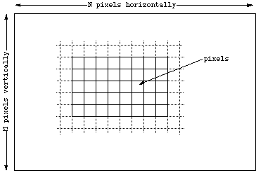
Note that bitmaps are always orientated horizontally and vertically. Pixels
should be considered square although they may have other aspect ratios in
practice.
Colour "depth"Each pixel in a bitmap contains certain information, usually interpreted as colour information. The information content is always the same for all the pixels in a particular bitmap. The amount of colour information could be whatever the application requires but there are some standards, the main ones are described below. 1 bit (black and white)
This is the smallest possible information content that can be held for each pixel. The resulting bitmap is refereed to as monochrome or black and white. The pixels with a 0 are refereed to as black, pixels with a 1 are refereed to as white. Note that while only two states are possible they could be interpreted as any two colours, 0 is mapped to one colour, 1 is mapped to another colour. 8 bit greys
In this case each pixel takes 1 byte (8 bits) of storage resulting in 256 different states. If these states are mapped onto a ramp of greys from black to white the bitmap is refereed to as a greyscale image. By convention 0 is normally black and 255 white. The grey levels are the numbers in between, for example, in a linear scale 127 would be a 50% grey level. 
In any particular application the range of grey values can be anything, it is most common to map the levels 0-255 onto a 0-1 scale but some programs will map it onto a 0-65535 scale (see Apples colour specification system as an example). 24 bit RGB
This is the next step from 8 bit grey, now there is 8 bits allocated to each red, green, and blue component. In each component the value of 0 refers to no contribution of that colour, 255 refers to fully saturated contribution of that colour. Since each component has 256 different states there are a total of 16777216 possible colours. 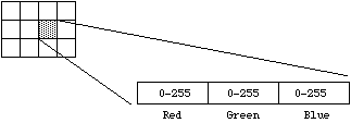
This idea of RGB colour space is a fundamental concept in computer graphics. In RGB space any colour is represented as a point inside a colour cube with orthogonal axes r,g,b. 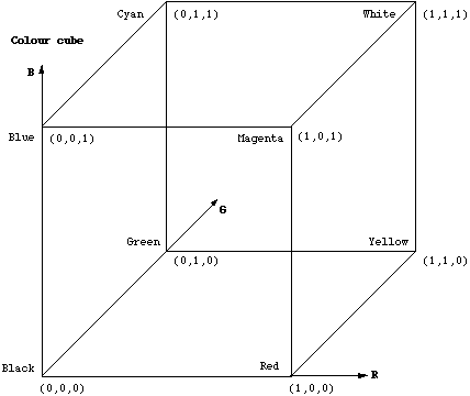
Note that grey values form a straight line from black to white along the diagonal of the cube, r = g = b. 8 bit indexed colour
Indexed colour is a more economical way of storing colour bitmaps without using 3 bytes per pixel. As with 8 bit grey bitmaps each pixel has one byte associated with it only now the value in that byte is no longer a colour value but an index into a table of colours, called a palette or colour table. 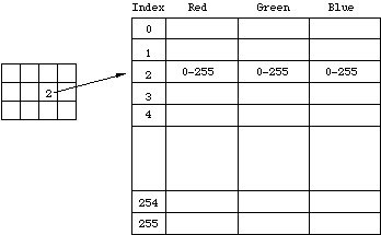
There are a number of interesting attributes of such a colour indexing system. If there are less than 256 colours in the image then this bitmap will be the same quality as a 24 bit bitmap but it can be stored with one third the data. Interesting colouring and animation effects can be achieved by simply modifying the palette, this immediately changes the appearance of the bitmap and with careful design can lead to intentional changes in the visual appearance of the bitmap. A common operation that reduces the size of large 24 bit bitmaps is to convert them to indexed colour with an optimised palette, that is, a palette which best represents the colours available in the bitmap. 4 bit indexed colour
This is identical to 8 bit colour except now only half a byte, 4 bits are used for the index. This supports a table of up to 16 colours. 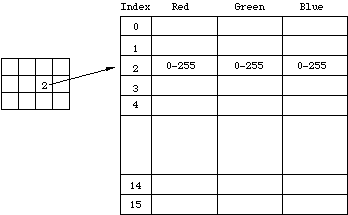 32 bit RGB
This is normally the same as 24 bit colour but with an extra 8 bit bitmap known as an alpha channel. This channel can be used to create masked areas or represent transparency.  16 bit RGB
This is generally a direct system with 5 bits per colour component and a 1 bit alpha channel. 
ResolutionResolution is an attribute of a bitmap that is necessary when visually viewing or printing bitmaps because pixels by themselves have no explicit dimensions. Resolution is normally specified in pixels per inch but could be in terms of any other unit of measure. Most printing processes retain the pixels per inch (DPI) units for historical reasons. On devices with nn rectangular pixels the resolution may be specified as two numbers, the horizontal and vertical resolution. The concept of resolution being independent of the information content of a bitmap is very important, given a constant colour depth then the information content between different bitmaps is only related to the number of pixels vertically and horizontally. The quality however, when the bitmap is displayed or printed does depend on the resolution. Since the resolution determines the size of a pixel it can also be used to modify the size of the overall image. As an example consider one bitmap which is 200 pixels horizontally and 100 pixels vertically. If this bitmap was printed at 100DPI then it would measure 2 inches by 1 inch. If however the same bitmap was printed at 200 DPI then it would only measure 1 inch by half an inch. 
Whenever a bitmap is displayed on a computer monitor resolution need to be considered. Most computer monitors have a range of resolution from 60DPI at the low resolution end to 120DPI for high resolution displays. As with printed matter the higher the resolution the less apparent the pixel nature of the bitmap will be. As a further example the following two images are identical in information content, they do however have different resolutions and hence different pixel sizes. The smaller is 80DPI and the larger is 30DPI. The pixels are much more evident in the larger version. 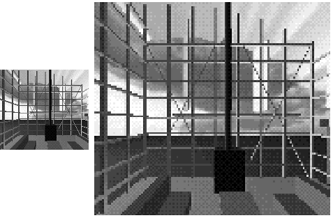
This is not the whole story when it comes to representing bitmaps on physical devices because different devices have different colour depth capabilities. Colour depth conversion.Very often it is necessary to represent a bitmap with one colour depth onto a device with different colour depth capabilities. Of course if the destination device has better colour than the bitmap then there is no issue since the bitmap can be exactly represented. In the reverse situation where the destination has different and lower capabilities, then the bitmap has to be converted into something that gives the best possible representation. As an example consider the problem of representing greyscale images on monochrome (black and white) devices. This is achieved by using a variable number of black and white pixels to represent a grey level. Fortunately the black and white device usually has much higher resolution than the bitmap so there are a number of pixels available to create the greyscale approximation. Consider a 75DPI greyscale bitmap to be displayed on a 300DPI black and white printer. There is a matrix of 4x4 black and white pixels that can be used to represent each greyscale pixel. 
There are a number of techniques that can be used to form the corresponding arrangement of black and white pixels, one technique is called dithering. Even using dithering there are lots of possible algorithms for deciding the dithered pixel arrangement. The following shows a grey level ramp with the corresponding black and white dithered examples (greatly enlarged) using pattern and diffusion dithering. 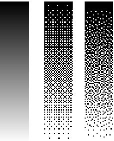
As already mentioned there are other methods of converting bitmaps of high colour depth into those of lower colour depth but higher resolution, on such technique used in the printing industry is called screening. Screening will not be discussed here except to say that it approximates grey levels by different size objects (the size of the object is proportional to the grey level) The objects are arranged on in a regular matrix which is at some angle to the horizontal. The most commonly used imaging objects are dots, lines and rectangles. The following shows a grey level ramp with the corresponding black and white screened examples (greatly enlarged) using dot and line screens. 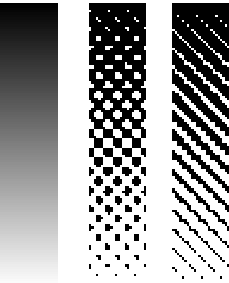
The above discussion and examples of colour depth conversion have been made with respect to greyscale images. Converting high colour depth images to low colour depth representations is no different in concept, generally the process is just done three times, one for each colour component. Bitmap StorageThe most straightforward way of storing a bitmap is simply to list the bitmap information, byte after byte, row by row. Files stored by this method are often called RAW files. The amount of disk storage required for any bitmap is easy to calculate given the bitmap dimensions (N x M) and colour depth in bits (B). The formula for the file size in KBytes is 
where N and M are the number of horizontal and vertical pixels, B is the number of bits per pixel. The following table shows the file sizes of a few bitmap types if they are stored in RAW format.
 image dimensions     colour depth     file size
    128 x 128             1 bit            2 KB
                          8 bits          16 KB
                         24 bits          48 KB
    256 x 256             1 bit            8 KB
                          8 bits          64 KB
                         24 bits         192 KB
     1K x 1K              1 bit          128 KB
                          8 bits           1 MB
                         24 bits           3 MB
As can be seen from this table, large 24bit images will result in very large files, this is why compression becomes important. There are a large number of file formats used for storing compressed bitmaps from the trivial to the very complicated. The complicated formats exist because of the very large bitmap files that would exist if compression was not used. There are two broad categories of compressed file format, those which are lossless (retain the bitmaps perfectly) and those which are lossy. The following shows the main hierarchy of compression techniques. 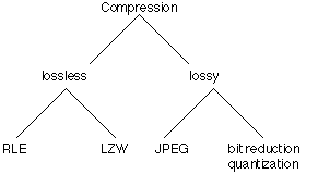
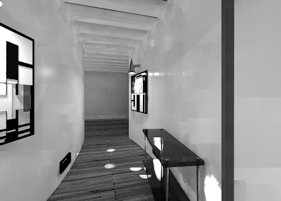
The crudest way of reducing the size of bitmap files is to reduce the colour information, this is called bit reduction or quantization. For example one could convert 24 bit bitmaps to 8 bit indexed bitmaps using dithering to simulate the lost colours. The most common lossy format by far is JPEG, a description of how it works is well outside the scope of this discussion. Its main advantage is that it can offer vastly better compression ratios than the lossless formats. For example consider the following bitmap the original of which is 500 x 350 pixels at 24 bit colour. Using the formula given earlier the uncompressed file size is 500 x 350 x 24 / 8 / 1024 = 513K 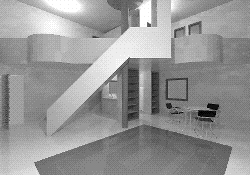
Saved in greyscale (bit depth reduction) the file is 171K (3 times smaller),
saved and compressed using
RLE it is 388K (75% of the original), saved using
LZW compression it is 188K (36% of the original), saved as JPEG it is 30K (a
compression ratio of 17:1). 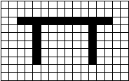
If this was to be stored in RAW form it would need 16 bytes per row for all 10 rows. However the first two rows are all the same level so it is more efficient to simply save the number of same colours in a run along with the run colour. The first two rows instead of needing 16 bytes only need 2 bytes each. In raw format the first three rows would be 0 0 0 0 0 0 0 0 0 0 0 0 0 0 0 0 0 0 0 0 0 0 0 0 0 0 0 0 0 0 0 0 0 0 1 1 1 1 1 1 1 1 1 1 1 1 0 0Using run length encoding the first three rows would be
	16 0
	16 0
	2 0 12 1 2 0
While there are more details involved in actual implementations of RLE than described here this is the basic principle behind run length encoding. In order for RLE to achieve some degree of compression there needs to be runs of the same colour, for this reason it is unlikely to be useful for highly coloured images such as 24 bit photographs. |